Information injection-pump assembly
ZEXEL
104760-2310
1047602310

Rating:
Cross reference number
ZEXEL
104760-2310
1047602310
Zexel num
Bosch num
Firm num
Name
Calibration Data:
Adjustment conditions
Test oil
1404 Test oil ISO4113orSAEJ967d
1404 Test oil ISO4113orSAEJ967d
Test oil temperature
degC
45
45
50
Nozzle
105780-0060
Bosch type code
NP-DN0SD1510
Nozzle holder
105780-2150
Opening pressure
MPa
13
13
13.3
Opening pressure
kgf/cm2
133
133
136
Injection pipe
157805-7320
Injection pipe
Inside diameter - outside diameter - length (mm) mm 2-6-450
Inside diameter - outside diameter - length (mm) mm 2-6-450
Joint assembly
157641-4720
Tube assembly
157641-4020
Transfer pump pressure
kPa
20
20
20
Transfer pump pressure
kgf/cm2
0.2
0.2
0.2
Direction of rotation (viewed from drive side)
Right R
Right R
Injection timing adjustment
Pump speed
r/min
900
900
900
Average injection quantity
mm3/st.
30.5
30.1
30.9
Difference in delivery
mm3/st.
2
Basic
*
Injection timing adjustment_02
Pump speed
r/min
2600
2600
2600
Average injection quantity
mm3/st.
27
24.5
29.5
Injection timing adjustment_03
Pump speed
r/min
2500
2500
2500
Average injection quantity
mm3/st.
30.7
28.6
32.8
Injection timing adjustment_04
Pump speed
r/min
2300
2300
2300
Average injection quantity
mm3/st.
30.2
28.2
32.2
Injection timing adjustment_05
Pump speed
r/min
1800
1800
1800
Average injection quantity
mm3/st.
30.6
28.6
32.6
Injection timing adjustment_06
Pump speed
r/min
1200
1200
1200
Average injection quantity
mm3/st.
30.9
29.4
32.4
Injection timing adjustment_07
Pump speed
r/min
900
900
900
Average injection quantity
mm3/st.
30.5
29.6
31.4
Injection timing adjustment_08
Pump speed
r/min
600
600
600
Average injection quantity
mm3/st.
31.3
29.5
33.1
Injection quantity adjustment
Pump speed
r/min
2600
2600
2600
Average injection quantity
mm3/st.
27
25
29
Difference in delivery
mm3/st.
4.5
Basic
*
Injection quantity adjustment_02
Pump speed
r/min
2800
2800
2800
Average injection quantity
mm3/st.
6.5
Governor adjustment
Pump speed
r/min
290
290
290
Average injection quantity
mm3/st.
9
8
10
Difference in delivery
mm3/st.
1.1
Basic
*
Governor adjustment_02
Pump speed
r/min
290
290
290
Average injection quantity
mm3/st.
9
8
10
Governor adjustment_03
Pump speed
r/min
500
500
500
Average injection quantity
mm3/st.
3
Boost compensator adjustment
Pump speed
r/min
600
600
600
Average injection quantity
mm3/st.
16.9
10.9
22.9
Remarks
From idle
From idle
Timer adjustment
Pump speed
r/min
100
100
100
Average injection quantity
mm3/st.
40
40
Difference in delivery
mm3/st.
15
Basic
*
Speed control lever angle
Pump speed
r/min
290
290
290
Average injection quantity
mm3/st.
4
Remarks
Magnet OFF
Magnet OFF
Speed control lever angle_02
Pump speed
r/min
900
900
900
Average injection quantity
mm3/st.
0
0
0
Remarks
Magnet OFF
Magnet OFF
0000000901
Pump speed
r/min
900
900
900
Overflow quantity
cm3/min
390
258
522
Stop lever angle
Pump speed
r/min
900
900
900
Pressure
kPa
372.5
343
402
Pressure
kgf/cm2
3.8
3.5
4.1
Basic
*
Stop lever angle_02
Pump speed
r/min
900
900
900
Pressure
kPa
372.5
343
402
Pressure
kgf/cm2
3.8
3.5
4.1
Stop lever angle_03
Pump speed
r/min
1800
1800
1800
Pressure
kPa
578.5
549
608
Pressure
kgf/cm2
5.9
5.6
6.2
Stop lever angle_04
Pump speed
r/min
2500
2500
2500
Pressure
kPa
745.5
716
775
Pressure
kgf/cm2
7.6
7.3
7.9
0000001101
Pump speed
r/min
900
900
900
Timer stroke
mm
2.9
2.7
3.1
Basic
*
_02
Pump speed
r/min
900
900
900
Timer stroke
mm
2.9
2.6
3.2
_03
Pump speed
r/min
1200
1200
1200
Timer stroke
mm
4.7
4.1
5.3
_04
Pump speed
r/min
1800
1800
1800
Timer stroke
mm
8.1
7.3
8.9
_05
Pump speed
r/min
2300
2300
2300
Timer stroke
mm
9.7
9.2
10.2
0000001201
Max. applied voltage
V
8
8
8
Test voltage
V
13
12
14
Timing setting
K dimension
mm
3.3
3.2
3.4
KF dimension
mm
7.24
7.14
7.34
MS dimension
mm
1.8
1.7
1.9
Control lever angle alpha
deg.
23
19
27
Control lever angle beta
deg.
42
37
47
Control lever angle gamma
deg.
11
10.5
11.5
Test data Ex:
0000001801 DASHPOT ADJUSTMENT
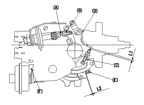
Adjustment of the dash pot
1. Insert a block gauge L1 (thickness gauge) between the idle set screw (C) and the control lever (D).
2. In the above condition, adjust the position of the dash pot so that the dash pot adjustment screw (A) contacts the push rod and then fix the screw using the nut (B).
TT
Note:
(1)Confirm that the dashpot and control lever contact faces are smooth.
(2)Confirm that the control lever returns to the idling position.
ISC actuator installation
1. Maintain the control lever in the idling position.
2. Fix actuator bracket (F) so that the gap between the control lever and the ISC lever's roller (E) is L2.
----------
T=6~7N-m(0.6~0.7kgf-m) L1=2.7+-0.05mm L2=1.0+1.0-0.5mm
----------
L1=2.7+-0.05mm L2=1.0+1.0-0.5mm
----------
T=6~7N-m(0.6~0.7kgf-m) L1=2.7+-0.05mm L2=1.0+1.0-0.5mm
----------
L1=2.7+-0.05mm L2=1.0+1.0-0.5mm
0000001901 POTENTIOMETER ADJUSTMENT
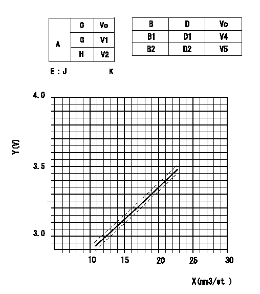
Adjustment of the potentiometer
In the following condition, change the installation position of the potentiometer to adjust the output voltage to within the specified values.
Measure the injection quantity at control lever position a (shim thickness = approximately L mm) at N = N1 r/min, determine the voltage using the formula, and adjust the potentiometer.
A:Performance standards
C:Position of the control lever
N:Pump speed
Vo:Output voltage
E:Conversion formula
G:Idling
H:Full speed
K:Applied voltage
X:Injection quantity (cm3/1,000st)
Y:Voltage (V)
R:At target value Q1cm3/1,000 st, set voltage at V3 (V).
M:The switch voltage specification is the value when the idle lever position is V6.
B:Conversion point
B1:ON-->OFF
B2:OFF-->ON
D:Lever opening (from idle)
----------
N1=600r/min a=10.3deg L=5.6mm Q1=-cm3/1,000st V3=-V V6=-V
----------
V1=Above 0.5V V2=Below 9.6V V4=-V V5=-V K=10V D1=5.0+-2.5deg D2=Above 23.5deg J:V+-0.03=0.0459X+2.4219
----------
N1=600r/min a=10.3deg L=5.6mm Q1=-cm3/1,000st V3=-V V6=-V
----------
V1=Above 0.5V V2=Below 9.6V V4=-V V5=-V K=10V D1=5.0+-2.5deg D2=Above 23.5deg J:V+-0.03=0.0459X+2.4219
0000002001 W-CSD ADJUSTMENT
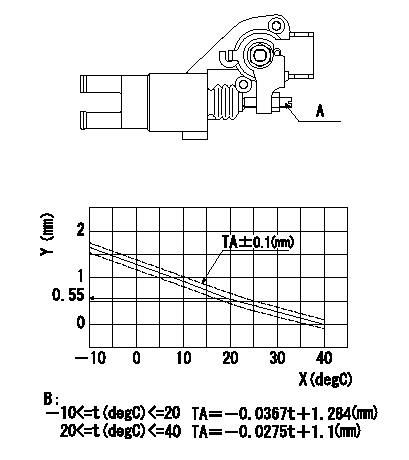
Adjustment of the W-CSD
Adjust the timer stroke using the screw so that it is as determined from the graph.
Caution: The temperature of the wax at adjustment must not exceed a.
A:Screw
B:Timer stroke graph
X:Temperature t
Y:Timer stroke TA
----------
a=30degC
----------
----------
a=30degC
----------
Information:
ACTION REQUIRED
Refer to the attached Rework Procedure.
OWNER NOTIFICATION
U.S. and Canadian owners will receive the attached Owner Notification.
SERVICE CLAIM ALLOWANCES
Caterpillar Dealer Suggested Customer Suggested
Parts % Labor Hrs% Parts % Labor Hrs% Parts % Labor Hrs%
100% 100% 0% 0% 0% 0%
This is a 4.0-hour job
PARTS DISPOSITION
Handle the parts in accordance with your Warranty Bulletin on warranty parts handling.
MAKE EVERY EFFORT TO COMPLETE THIS PROGRAM AS SOON AS POSSIBLE.
COPY OF OWNER NOTIFICATION FOR U.S. AND CANADIAN OWNERS
XYZ Corporation
3240 Arrow Drive
Anywhere, YZ 99999
PRIORITY - PRODUCT IMPROVEMENT PROGRAM FOR REPLACING THE DIESEL PARTICULATE FILTER ON CERTAIN SKID STEER LOADERS AND COMPACT TRACK LOADERS
MODELS INVOLVED - 272D Skid Steer Loaders and 299D Compact Track Loaders
Dear Cat Product Owner:
The diesel particulate filter needs to be replaced on certain 272D Skid Steer Loaders and 299D Compact Track Loaders. The existing diesel particulate filter has been installed incorrectly which can result in decreased performance of the filter. You will not be charged for the service performed.
Contact your local Cat dealer immediately to schedule this service. The dealer will advise you of the time required to complete this service.
Please refer the dealer to their Service Letter dated 06Aug2012 when scheduling this service.
We regret the inconvenience this may cause you, but urge you to have this service performed as soon as possible to prevent unscheduled downtime.
Caterpillar Inc.
Identification #(s)
Attached to 06Aug2012 Service Letter
Rework Procedure
1. Remove the cooling package. Refer UENR2328, Disassembly and Assembly, "Radiator and Hydraulic Oil Cooler - Removal Procedure".
2. Record the diesel particulate filter serial number prior to installing. The serial number is etched into the diesel particulate filter housing in the location shown in Image1.1.1. It is the lower set of digits. Send the new diesel particulate filter serial number and machine serial number to Rob McHardy (MCHARDY_ROBERT_W).
Image1.1.1
Image1.1.2
3. Replace the 389-5370 Diesel Particulate Filter section. Refer to UENR0129, Disassembly and Assembly, "Diesel Particulate Filter - Remove and Install" and "Diesel Particulate Filter - Disassemble".
4. When performing this work, replace the three 389-5373 Gaskets (metal) for the diesel particulate filter section and the 345-3579 Gasket between the turbo flange and the DOC inlet.
5. Ensure the diesel particulate filter is installed with the exhaust flowing in the direction of the arrow that is on the diesel particulate filter. Refer to Image1.2.1.
6. Cover both ends of the diesel particulate filter to ensure the ash and soot remain within the diesel particulate filter. Package the diesel particulate filter according to REHS3827, "Procedure to Handle and Ship Diesel Particulate Filters (DPF) and Catalytic Converter Mufflers (CCM)".
7. Connect Caterpillar Electronic Technician (ET). Version 2012A is acceptable but version 2012B is recommended. Go to Service Tab and select "DPF Soot Load Reset". At the next two screens select the "Reset" button in the bottom left corner.
Image1.2.1