Information injection-pump assembly
BOSCH
9 460 615 031
9460615031
ZEXEL
104749-6650
1047496650
ISUZU
8944464030
8944464030
Rating:
Components :
| 0. | INJECTION-PUMP ASSEMBLY | 104749-6650 |
| 1. | _ | |
| 2. | FUEL INJECTION PUMP | 104649-6000 |
| 3. | NUMBER PLATE | |
| 4. | _ | |
| 5. | CAPSULE | |
| 6. | ADJUSTING DEVICE | |
| 7. | NOZZLE AND HOLDER ASSY | 105158-2061 |
| 8. | Nozzle and Holder | |
| 9. | Open Pre:MPa(Kqf/cm2) | 14.7(150) |
| 10. | NOZZLE-HOLDER | 105088-1061 |
| 11. | NOZZLE | 105007-1080 |
Scheme ###:

| 1/6. | [1] | 146601-0100 | PACKING RING |
| 6. | [1] | 146100-0120 | SUPPLY PUMP |
| 9. | [1] | 146103-0000 | COVER |
| 10. | [2] | 139104-0000 | FLAT-HEAD SCREW |
| 12. | [1] | 146200-0520 | DRIVE SHAFT |
| 12/1. | [1] | 146200-0500 | DRIVE SHAFT |
| 12/2. | [1] | 146201-0000 | WOODRUFF KEY |
| 12/3. | [2] | 146202-0100 | DAMPER |
| 12/4. | [1] | 146203-0000 | TOOTHED GEAR |
| 17. | [1] | 146204-0000 | PLAIN WASHER |
| 20. | [1] | 146210-1920 | ROLLER SET |
| 24. | [1] | 146303-0100 | BEARING PIN |
| 25. | [1] | 146304-0000 | BEARING PIN |
| 26. | [1] | 146305-0000 | CLAMPING BAND |
| 27. | [1] | 146205-0000 | SLOTTED WASHER |
| 29. | [1] | 146220-0020 | CAM PLATE |
| 30. | [1] | 146600-0800 | O-RING |
| 31. | [1] | 146300-2000 | PUMP PLUNGER |
| 32. | [1] | 146301-0000 | SLIDING PIECE |
| 33. | [1] | 146603-0700 | SHIM D17.5&7.5T0.60 |
| 34. | [1] | 146302-3700 | COMPRESSION SPRING |
| 35/1. | [0] | 146603-0700 | SHIM D17.5&7.5T0.60 |
| 35/1. | [0] | 146603-0800 | SHIM D17.5&7.5T0.70 |
| 35/1. | [0] | 146603-0900 | SHIM D17.5&7.5T0.90 |
| 35/1. | [0] | 146603-1000 | SHIM D17.5&7.5T1.00 |
| 35/1. | [0] | 146603-1100 | SHIM D17.5&7.5T1.20 |
| 35/1. | [0] | 146603-3600 | SHIM D17.5&7.5T2.40 |
| 36. | [1] | 146600-0800 | O-RING |
| 37. | [1] | 146310-0700 | COVER |
| 38. | [2] | 146620-5000 | BLEEDER SCREW |
| 39. | [1] | 146310-0100 | COVER |
| 40. | [2] | 146620-5000 | BLEEDER SCREW |
| 43. | [1] | 146230-0000 | SHIM |
| 44. | [1] | 146230-0100 | PLAIN WASHER |
| 45. | [1] | 146231-0001 | SLOTTED WASHER |
| 47. | [2] | 146233-0000 | SLOTTED WASHER |
| 48/1. | [1] | 146603-0000 | SHIM D17.0&5.2T0.50 |
| 48/1. | [1] | 146603-0100 | SHIM D17.0&5.2T0.80 |
| 48/1. | [1] | 146603-0200 | SHIM D17.0&5.2T1.00 |
| 48/1. | [1] | 146603-0300 | SHIM D17.0&5.2T1.20 |
| 48/1. | [1] | 146603-0400 | SHIM D17.0&5.2T1.50 |
| 48/1. | [1] | 146603-0500 | SHIM D17.0&5.2T1.80 |
| 48/1. | [1] | 146603-0600 | SHIM D17.0&5.2T2.00 |
| 48/1. | [1] | 146690-1400 | SHIM |
| 48/1. | [1] | 146690-1500 | SHIM D17&5.2T1.1 |
| 48/1. | [1] | 146690-1600 | SHIM |
| 48/1. | [1] | 146690-1700 | SHIM D17&5.2T1.4 |
| 48/1. | [1] | 146690-1800 | SHIM |
| 48/1. | [1] | 146690-1900 | SHIM |
| 48/1. | [1] | 146690-5800 | SHIM |
| 48/1. | [1] | 146690-5900 | SHIM |
| 48/1. | [1] | 146690-6000 | SHIM D17&5.2T2.3 |
| 48/1. | [1] | 146690-6100 | SHIM |
| 48/1. | [1] | 146690-6200 | SHIM |
| 48/1. | [1] | 146690-6300 | SHIM |
| 48/1. | [1] | 146690-6400 | SHIM D17&5.2T2.7 |
| 48/1. | [1] | 146690-6500 | SHIM |
| 48/1. | [1] | 146690-6600 | SHIM |
| 48/1. | [1] | 146690-6700 | SHIM |
| 48/1. | [1] | 146690-6800 | SHIM |
| 48/1. | [1] | 146690-6900 | SHIM |
| 48/1. | [1] | 146690-7000 | SHIM |
| 48/1. | [1] | 146690-7100 | SHIM D17&5.2T3.4 |
| 48/1. | [1] | 146690-7200 | SHIM D17&5.2T0.4 |
| 48/1. | [1] | 146690-7300 | SHIM D17&5.2T0.6 |
| 48/1. | [1] | 146690-7400 | SHIM D17&5.2T0.7 |
| 48/1. | [1] | 146690-7500 | SHIM |
| 48/1. | [1] | 146690-7800 | SHIM |
| 49. | [2] | 146234-0020 | GUIDE PIN |
| 50. | [1] | 146400-7920 | HYDRAULIC HEAD |
| 50. | [1] | 146400-7920 | HYDRAULIC HEAD |
| 50. | [1] | 146400-7920 | HYDRAULIC HEAD |
| 51. | [1] | 146600-0000 | O-RING |
| 52/1. | [1] | 146420-0000 | SHIM D9.5&3.0T1.90 |
| 52/1. | [1] | 146420-0100 | SHIM D9.5&3.0T1.92 |
| 52/1. | [1] | 146420-0200 | SHIM D9.5&3.0T1.94 |
| 52/1. | [1] | 146420-0300 | SHIM D9.5&3.0T1.96 |
| 52/1. | [1] | 146420-0400 | SHIM D9.5&3.0T1.98 |
| 52/1. | [1] | 146420-0500 | SHIM D9.5&3.0T2.00 |
| 52/1. | [1] | 146420-0600 | SHIM D9.5&3.0T2.02 |
| 52/1. | [1] | 146420-0700 | SHIM D9.5&3.0T2.04 |
| 52/1. | [1] | 146420-0800 | SHIM D9.5&3.0T2.06 |
| 52/1. | [1] | 146420-0900 | SHIM D9.5&3.0T2.08 |
| 52/1. | [1] | 146420-1000 | SHIM D9.5&3.0T2.10 |
| 52/1. | [1] | 146420-1100 | SHIM D9.5&3.0T2.12 |
| 52/1. | [1] | 146420-1200 | SHIM D9.5&3.0T2.14 |
| 52/1. | [1] | 146420-1300 | SHIM D9.5&3.0T2.16 |
| 52/1. | [1] | 146420-1400 | SHIM D9.5&3.0T2.18 |
| 52/1. | [1] | 146420-1500 | SHIM D9.5&3.0T2.20 |
| 52/1. | [1] | 146420-1600 | SHIM D9.5&3.0T2.22 |
| 52/1. | [1] | 146420-1700 | SHIM D9.5&3.0T2.24 |
| 52/1. | [1] | 146420-1800 | SHIM D9.5&3.0T2.26 |
| 52/1. | [1] | 146420-1900 | SHIM D9.5&3.0T2.28 |
| 52/1. | [1] | 146420-2000 | SHIM D9.5&3.0T2.30 |
| 52/1. | [1] | 146420-2100 | SHIM D9.5&3.0T2.32 |
| 52/1. | [1] | 146420-2200 | SHIM D9.5&3.0T2.34 |
| 52/1. | [1] | 146420-2300 | SHIM D9.5&3.0T2.36 |
| 52/1. | [1] | 146420-2400 | SHIM D9.5&3.0T2.38 |
| 52/1. | [1] | 146420-2500 | SHIM D9.5&3.0T2.40 |
| 52/1. | [1] | 146420-2600 | SHIM D9.5&3.0T2.42 |
| 52/1. | [1] | 146420-2700 | SHIM D9.5&3.0T2.44 |
| 52/1. | [1] | 146420-2800 | SHIM D9.5&3.0T2.46 |
| 52/1. | [1] | 146420-2900 | SHIM D9.5&3.0T2.48 |
| 52/1. | [1] | 146420-3000 | SHIM D9.5&3.0T2.50 |
| 52/1. | [1] | 146420-3100 | SHIM D9.5&3.0T2.52 |
| 52/1. | [1] | 146420-3200 | SHIM D9.5&3.0T2.54 |
| 52/1. | [1] | 146420-3300 | SHIM D9.5&3.0T2.56 |
| 52/1. | [1] | 146420-3400 | SHIM D9.5&3.0T2.58 |
| 52/1. | [1] | 146420-3500 | SHIM D9.5&3.0T2.60 |
| 52/1. | [1] | 146420-3600 | SHIM D9.5&3.0T2.62 |
| 52/1. | [1] | 146420-3700 | SHIM D9.5&3.0T2.64 |
| 52/1. | [1] | 146420-3800 | SHIM D9.5&3.0T2.66 |
| 52/1. | [1] | 146420-3900 | SHIM D9.5&3.0T2.68 |
| 52/1. | [1] | 146420-4000 | SHIM D9.5&3.0T2.70 |
| 52/1. | [1] | 146420-4100 | SHIM D9.5&3.0T2.72 |
| 52/1. | [1] | 146420-4200 | SHIM D9.5&3.0T2.74 |
| 52/1. | [1] | 146420-4300 | SHIM D9.5&3.0T2.76 |
| 52/1. | [1] | 146420-4400 | SHIM D9.5&3.0T2.78 |
| 52/1. | [1] | 146420-4500 | SHIM D9.5&3.0T2.80 |
| 52/1. | [1] | 146420-4600 | SHIM D9.5&3.0T2.82 |
| 52/1. | [1] | 146420-4700 | SHIM D9.5&3.0T2.84 |
| 52/1. | [1] | 146420-4800 | SHIM D9.5&3.0T2.86 |
| 52/1. | [1] | 146420-4900 | SHIM D9.5&3.0T2.88 |
| 52/1. | [1] | 146420-5000 | SHIM D9.5&3.0T2.90 |
| 52/1. | [1] | 146420-5100 | SHIM |
| 52/1. | [1] | 146420-5200 | SHIM |
| 52/1. | [1] | 146420-5300 | SHIM |
| 52/1. | [1] | 146420-5400 | SHIM D9.5&3.0T1.80 |
| 52/1. | [1] | 146420-5500 | SHIM D9.5&3.0T1.82 |
| 52/1. | [1] | 146420-5600 | SHIM D9.5&3.0T1.84 |
| 52/1. | [1] | 146420-5700 | SHIM D9.5&3.0T1.86 |
| 52/1. | [1] | 146420-5800 | SHIM D9.5&3.0T1.88 |
| 54. | [4] | 146433-0100 | GASKET D12&6.4T1.00 |
| 55. | [4] | 146430-0120 | DELIVERY-VALVE ASSEMBLY |
| 56. | [4] | 146432-0000 | COMPRESSION SPRING |
| 58. | [4] | 146440-0120 | FITTING |
| 60. | [3] | 139106-0100 | FLAT-HEAD SCREW |
| 66. | [1] | 146600-0100 | O-RING |
| 67. | [1] | 146702-3120 | MANIFOLD-PRESSURE COMP. |
| 67/1. | [1] | 146805-0320 | GOVERNOR COVER |
| 67/13. | [1] | 146621-1700 | UNION NUT |
| 67/14. | [1] | 146621-1800 | UNION NUT |
| 67/15. | [1] | 146526-2800 | BLEEDER SCREW |
| 67/16. | [1] | 146526-3500 | BLEEDER SCREW |
| 67/23. | [1] | 146626-2920 | BRACKET |
| 67/31. | [1] | 146710-0800 | BUSHING |
| 67/32. | [1] | 146711-0000 | PLATE |
| 67/33. | [1] | 139218-0400 | UNION NUT |
| 67/34. | [1] | 146712-0700 | BEARING PIN |
| 67/35. | [1] | 146621-0300 | UNION NUT |
| 67/36. | [1] | 146600-1400 | O-RING |
| 67/37. | [1] | 146710-0100 | BUSHING |
| 67/38. | [1] | 139506-0200 | GASKET D8.9&6.8T1.00 |
| 67/39. | [1] | 146620-0300 | CAPSULE |
| 67/40. | [1] | 026512-1540 | GASKET D15.4&12.2T1.50 |
| 67/41. | [1] | 146713-4100 | ADJUSTING PIN |
| 67/42. | [2] | 146714-0000 | PLATE |
| 67/43. | [1] | 146715-0000 | DIAPHRAGM |
| 67/44. | [1] | 139306-0100 | LOCKING WASHER |
| 67/45. | [1] | 013030-6040 | UNION NUT |
| 67/46. | [1] | 146716-0000 | UNION NUT |
| 67/47. | [1] | 146717-0400 | COILED SPRING |
| 67/48/1. | [1] | 146720-0000 | SPACER BUSHING L3.7 |
| 67/48/1. | [1] | 146720-0100 | SPACER BUSHING L3.9 |
| 67/48/1. | [1] | 146720-0200 | SPACER BUSHING L4.1 |
| 67/48/1. | [1] | 146720-0300 | SPACER BUSHING L4.3 |
| 67/48/1. | [1] | 146720-0400 | SPACER BUSHING L4.5 |
| 67/48/1. | [1] | 146720-0500 | SPACER BUSHING L4.7 |
| 67/48/1. | [1] | 146720-0600 | SPACER BUSHING L4.9 |
| 67/48/1. | [1] | 146720-0700 | SPACER BUSHING L5.1 |
| 67/48/1. | [1] | 146720-0800 | SPACER BUSHING |
| 67/48/1. | [1] | 146720-0900 | SPACER BUSHING L2.7 |
| 67/48/1. | [1] | 146720-1000 | SPACER BUSHING L2.9 |
| 67/48/1. | [1] | 146720-1100 | SPACER BUSHING L3.1 |
| 67/48/1. | [1] | 146720-1200 | SPACER BUSHING L3.3 |
| 67/48/1. | [1] | 146720-1300 | SPACER BUSHING L3.5 |
| 67/48/1. | [1] | 146720-1400 | SPACER BUSHING |
| 67/48/1. | [1] | 146720-1500 | SPACER BUSHING |
| 67/48/1. | [1] | 146720-1600 | SPACER BUSHING |
| 67/48/1. | [1] | 146720-1700 | SPACER BUSHING L3.4 |
| 67/48/1. | [1] | 146720-1800 | SPACER BUSHING |
| 67/48/1. | [1] | 146720-1900 | SPACER BUSHING L3.8 |
| 67/48/1. | [1] | 146720-2000 | SPACER BUSHING |
| 67/48/1. | [1] | 146720-2100 | SPACER BUSHING |
| 67/48/1. | [1] | 146720-2200 | SPACER BUSHING L4.4 |
| 67/48/1. | [1] | 146720-2300 | SPACER BUSHING L4.6 |
| 67/48/1. | [1] | 146720-2400 | SPACER BUSHING L4.8 |
| 67/48/1. | [1] | 146720-2500 | SPACER BUSHING |
| 67/48/1. | [1] | 146720-2600 | SPACER BUSHING |
| 67/48/1. | [1] | 146720-2700 | SPACER BUSHING |
| 67/48/1. | [1] | 146720-2800 | SPACER BUSHING |
| 67/48/1. | [1] | 146720-2900 | SPACER BUSHING |
| 67/48/1. | [1] | 146720-4500 | SPACER BUSHING |
| 67/48/1. | [1] | 146720-4600 | SPACER BUSHING |
| 67/48/1. | [1] | 146720-4700 | SPACER BUSHING |
| 67/48/1. | [1] | 146720-4800 | SPACER BUSHING |
| 67/48/1. | [1] | 146720-4900 | SPACER BUSHING |
| 67/48/1. | [1] | 146720-5000 | SPACER BUSHING |
| 67/48/1. | [1] | 146720-5100 | SPACER BUSHING |
| 67/48/1. | [1] | 146720-5200 | SPACER BUSHING |
| 67/48/1. | [1] | 146720-5300 | SPACER BUSHING |
| 67/48/1. | [1] | 146725-2500 | SPACER BUSHING |
| 67/48/1. | [1] | 146725-2600 | SPACER BUSHING |
| 67/48/1. | [1] | 146725-2700 | SPACER BUSHING |
| 67/48/1. | [1] | 146725-2800 | SPACER BUSHING |
| 67/48/1. | [1] | 146725-2900 | SPACER BUSHING L6.1 |
| 67/48/1. | [1] | 146725-3000 | SPACER BUSHING |
| 67/48/1. | [1] | 146725-3100 | SPACER BUSHING L6.3 |
| 67/48/1. | [1] | 146725-3200 | SPACER BUSHING |
| 67/48/1. | [1] | 146725-3300 | SPACER BUSHING |
| 67/48/1. | [1] | 146725-3400 | SPACER BUSHING |
| 67/48/1. | [1] | 146725-3500 | SPACER BUSHING |
| 67/48/1. | [1] | 146725-3600 | SPACER BUSHING |
| 67/48/1. | [1] | 146725-3700 | SPACER BUSHING L6.9 |
| 67/48/1. | [1] | 146725-3800 | SPACER BUSHING L7.0 |
| 67/48/1. | [1] | 146725-3900 | SPACER BUSHING |
| 67/48/1. | [1] | 146725-4000 | SPACER BUSHING |
| 67/48/1. | [1] | 146725-4100 | SPACER BUSHING |
| 67/48/1. | [1] | 146725-4200 | SPACER BUSHING |
| 67/48/1. | [1] | 146725-4300 | SPACER BUSHING L7.5 |
| 67/49. | [1] | 146721-0820 | COVER |
| 67/54. | [2] | 020006-1240 | BLEEDER SCREW |
| 67/55. | [2] | 020006-2040 | BLEEDER SCREW M6P1L20 4T |
| 67/56. | [1] | 146723-0200 | CONTROL LEVER |
| 67/57. | [1] | 146712-0100 | BEARING PIN |
| 67/58. | [2] | 146620-0600 | CAPSULE |
| 67/59. | [2] | 026506-1040 | GASKET D9.9&6.2T1 |
| 67/60. | [1] | 146724-0300 | ELEMENT |
| 67/61. | [1] | 146724-0600 | CAPSULE |
| 67/78. | [1] | 146600-4400 | SEAL RING |
| 67/98. | [2] | 013020-6040 | UNION NUT M6P1H5 |
| 67/99. | [2] | 014110-6440 | LOCKING WASHER |
| 67/100. | [1] | 146629-9200 | BRACKET |
| 67/200. | [1] | 139308-0300 | PLAIN WASHER |
| 67/201. | [1] | 146545-0300 | THREADED PIN |
| 67/201B. | [1] | 146545-0400 | THREADED PIN |
| 67/201C. | [1] | 146545-0500 | THREADED PIN |
| 67/202. | [1] | 139208-0100 | UNION NUT |
| 67/203. | [1] | 146600-1200 | O-RING |
| 68. | [1] | 146513-3020 | CONTROL SHAFT |
| 69. | [1] | 139310-0200 | PLAIN WASHER |
| 72. | [1] | 146535-3720 | CONTROL LEVER |
| 72B. | [1] | 146535-3820 | CONTROL LEVER |
| 73. | [1] | 014110-6440 | LOCKING WASHER |
| 75. | [1] | 013020-6040 | UNION NUT |
| 95. | [1] | 146551-4620 | FULCRUM LEVER |
| 104. | [2] | 146568-0000 | SLOTTED SPRING PIN |
| 105. | [2] | 026508-1140 | GASKET D11.4&8.2T1 |
| 106. | [2] | 146588-0500 | COILED SPRING |
| 107. | [1] | 146569-0300 | UNION NUT |
| 108. | [1] | 146570-0420 | GOVERNOR SHAFT |
| 109. | [1] | 146600-0400 | O-RING |
| 110/1. | [1] | 146571-0000 | SHIM D20.2&8.3T1.05 |
| 110/1. | [1] | 146571-0100 | SHIM D20.2&8.3T1.25 |
| 110/1. | [1] | 146571-0200 | SHIM D20.2&8.3T1.45 |
| 110/1. | [1] | 146571-0300 | SHIM D20.2&8.3T1.65 |
| 110/1. | [1] | 146571-0400 | SHIM D20.2&8.3T1.85 |
| 110/1. | [1] | 146571-0500 | SHIM D20.2&8.3T1.15 |
| 110/1. | [1] | 146571-0600 | SHIM D20.2&8.3T1.35 |
| 110/1. | [1] | 146571-0700 | SHIM D20.2&8.3T1.55 |
| 110/1. | [1] | 146571-0800 | SHIM D20.2&8.3T1.75 |
| 111. | [1] | 146602-0600 | PLAIN WASHER D20&8.4T1.40 |
| 112. | [1] | 146572-0020 | FLYWEIGHT ASSEMBLY |
| 114. | [1] | 146602-0500 | PLAIN WASHER D17&6.4T1.60 |
| 115. | [1] | 146575-2900 | SLIDING SLEEVE |
| 116. | [1] | 146576-0000 | SEALING CAP |
| 117/1. | [1] | 146577-1800 | PLUG L2.10 |
| 117/1. | [1] | 146577-1900 | PLUG L2.30 |
| 117/1. | [1] | 146577-2000 | PLUG L2.50 |
| 117/1. | [1] | 146577-2100 | PLUG L2.70 |
| 117/1. | [1] | 146577-2200 | PLUG L2.90 |
| 117/1. | [1] | 146577-2300 | PLUG L3.10 |
| 117/1. | [1] | 146577-2400 | PLUG L3.30 |
| 117/1. | [1] | 146577-2500 | PLUG L3.50 |
| 117/1. | [1] | 146577-2600 | PLUG L3.70 |
| 117/1. | [1] | 146577-2700 | PLUG L3.90 |
| 117/1. | [1] | 146577-2800 | PLUG L4.10 |
| 117/1. | [1] | 146577-2900 | PLUG L4.30 |
| 117/1. | [1] | 146577-3000 | PLUG L4.50 |
| 117/1. | [1] | 146577-3100 | PLUG L4.70 |
| 117/1. | [1] | 146577-3200 | PLUG L4.90 |
| 117/1. | [1] | 146577-3300 | PLUG L5.10 |
| 117/1. | [1] | 146577-6700 | PLUG L2.2 |
| 117/1. | [1] | 146577-6800 | PLUG L2.4 |
| 117/1. | [1] | 146577-6900 | PLUG L2.6 |
| 117/1. | [1] | 146577-7000 | PLUG L2.8 |
| 117/1. | [1] | 146577-7100 | PLUG |
| 117/1. | [1] | 146577-7200 | PLUG L3.2 |
| 117/1. | [1] | 146577-7300 | PLUG L3.4 |
| 117/1. | [1] | 146577-7400 | PLUG L3.6 |
| 117/1. | [1] | 146577-7500 | PLUG |
| 117/1. | [1] | 146577-7600 | PLUG L4.0 |
| 117/1. | [1] | 146577-7700 | PLUG L4.2 |
| 117/1. | [1] | 146577-7800 | PLUG |
| 117/1. | [1] | 146577-7900 | PLUG L4.6 |
| 117/1. | [1] | 146577-8000 | PLUG |
| 117/1. | [1] | 146577-8100 | PLUG |
| 117/1. | [1] | 146877-0000 | PLUG |
| 117/1. | [1] | 146877-0100 | PLUG L5.3 |
| 117/1. | [1] | 146877-0200 | PLUG L5.4 |
| 117/1. | [1] | 146877-0300 | PLUG |
| 117/1. | [1] | 146877-4700 | PLUG |
| 117/1. | [1] | 146877-4800 | PLUG |
| 117/1. | [1] | 146877-4900 | PLUG |
| 117/1. | [1] | 146877-5000 | PLUG |
| 123. | [4] | 146620-0500 | HEX-SOCKET-HEAD CAP SCREW |
| 130. | [1] | 146421-0020 | CAPSULE |
| 130/2. | [1] | 026508-1140 | GASKET D11.4&8.2T1 |
| 130/3. | [1] | 146422-0000 | BLEEDER SCREW |
| 130/4. | [1] | 146600-0500 | O-RING |
| 133. | [1] | 146600-0600 | O-RING |
| 134. | [1] | 146600-0700 | O-RING |
| 135. | [1] | 146110-0220 | CONTROL VALVE |
| 135/5. | [1] | 146114-0000 | SPRING WASHER |
| 136. | [1] | 146120-0120 | OVER FLOW VALVE |
| 137. | [2] | 026512-1540 | GASKET D15.4&12.2T1.50 |
| 138. | [1] | 146607-3420 | INLET UNION |
| 160. | [1] | 146628-7220 | PLATE |
| 200. | [1] | 146206-0100 | COILED SPRING |
| 205. | [1] | 146201-0100 | WOODRUFF KEY |
| 218. | [1] | 146587-7320 | COILED SPRING |
| 220. | [1] | 146587-7600 | COILED SPRING |
| 230. | [1] | 146629-9600 | BRACKET |
| 231. | [1] | 139106-0500 | FLAT-HEAD SCREW M6P1.0H25 |
| 236. | [1] | 139106-0400 | FLAT-HEAD SCREW |
| 237. | [1] | 146620-0200 | HEX-SOCKET-HEAD CAP SCREW |
| 240. | [1] | 146650-1220 | PULLING ELECTROMAGNET |
| 240/8. | [1] | 146600-1700 | O-RING |
| 243. | [1] | 146621-1000 | UNION NUT |
| 244. | [1] | 146613-5620 | PLATE |
| 245. | [3] | 026512-1840 | GASKET D17.9&12.2T1.50 |
| 246. | [1] | 146125-0020 | EYE BOLT |
| 247. | [1] | 146607-3520 | INLET UNION |
| 248. | [1] | 146614-0200 | SPACER BUSHING |
| 275. | [1] | 146629-9500 | BRACKET |
| 276. | [2] | 010010-2040 | BLEEDER SCREW |
| 277. | [2] | 014111-0440 | LOCKING WASHER |
| 280. | [1] | 146360-6620 | START ADVANCE ASSY |
| 281. | [1] | 146600-0800 | O-RING |
| 282. | [2] | 010206-1240 | HEX-SOCKET-HEAD CAP SCREW M6P1L12 |
| 287. | [1] | 020146-1440 | BLEEDER SCREW M6P1L14 |
| 450. | [1] | 146676-3120 | ADJUSTING DEVICE |
| 455. | [1] | 146541-8420 | RACK |
| 460. | [2] | 016010-0440 | LOCKING WASHER |
| 465. | [1] | 146616-4200 | SPACER BUSHING |
| 470. | [1] | 139106-0500 | FLAT-HEAD SCREW |
| 471. | [1] | 139106-0400 | FLAT-HEAD SCREW M6P1.0H12 |
| 473. | [1] | 010206-1640 | HEX-SOCKET-HEAD CAP SCREW M6P1L16 |
| 474. | [1] | 014110-6440 | LOCKING WASHER |
| 475. | [1] | 013020-6040 | UNION NUT M6P1H5 |
| 800S. | [1] | 146019-4720 | PUMP HOUSING |
| 800S/1/6. | [1] | 146601-0100 | PACKING RING |
| 804S. | [1] | 146232-0320 | COMPRESSION SPRING |
| 805S. | [1] | 146574-0120 | PARTS SET |
| 810S. | [1] | 146600-1120 | REPAIR SET |
| 812S. | [1] | 146600-1920 | PARTS SET |
| 903. | [1] | 146672-3420 | PULSE GENERATOR |
| 903/2. | [1] | 146600-1300 | O-RING |
| 906. | [1] | 146646-7900 | NAMEPLATE |
Include in #2:
104749-6650
as INJECTION-PUMP ASSEMBLY
Cross reference number
BOSCH
9 460 615 031
9460615031
ZEXEL
104749-6650
1047496650
ISUZU
8944464030
8944464030
Zexel num
Bosch num
Firm num
Name
104749-6650
9 460 615 031
8944464030 ISUZU
INJECTION-PUMP ASSEMBLY
4EC1 * K
4EC1 * K
Calibration Data:
Adjustment conditions
Test oil
1404 Test oil ISO4113orSAEJ967d
1404 Test oil ISO4113orSAEJ967d
Test oil temperature
degC
45
45
50
Nozzle
105000-2010
Bosch type code
NP-DN12SD12TT
Nozzle holder
105780-2080
Opening pressure
MPa
14.7
14.7
15.19
Opening pressure
kgf/cm2
150
150
155
Injection pipe
Inside diameter - outside diameter - length (mm) mm 2-6-840
Inside diameter - outside diameter - length (mm) mm 2-6-840
Transfer pump pressure
kPa
20
20
20
Transfer pump pressure
kgf/cm2
0.2
0.2
0.2
Direction of rotation (viewed from drive side)
Right R
Right R
Injection timing adjustment
Pump speed
r/min
1000
1000
1000
Boost pressure
kPa
42.65
41.3
44
Boost pressure
mmHg
320
310
330
Average injection quantity
mm3/st.
39.6
39.1
40.1
Difference in delivery
mm3/st.
3.5
Basic
*
Remarks
CBS
CBS
Injection timing adjustment_02
Pump speed
r/min
1250
1250
1250
Boost pressure
kPa
69.35
68
70.7
Boost pressure
mmHg
520
510
530
Average injection quantity
mm3/st.
43.5
43
44
Difference in delivery
mm3/st.
3.5
Basic
*
Remarks
Full
Full
Injection timing adjustment_03
Pump speed
r/min
2800
2800
2800
Boost pressure
kPa
69.35
68
70.7
Boost pressure
mmHg
520
510
530
Average injection quantity
mm3/st.
18.1
14.6
21.6
Injection timing adjustment_04
Pump speed
r/min
2500
2500
2500
Boost pressure
kPa
69.35
68
70.7
Boost pressure
mmHg
520
510
530
Average injection quantity
mm3/st.
34.5
32.4
36.6
Injection timing adjustment_05
Pump speed
r/min
1250
1250
1250
Boost pressure
kPa
69.35
68
70.7
Boost pressure
mmHg
520
510
530
Average injection quantity
mm3/st.
43.5
42.5
44.5
Remarks
Full
Full
Injection timing adjustment_06
Pump speed
r/min
1250
1250
1250
Boost pressure
kPa
0
0
0
Boost pressure
mmHg
0
0
0
Average injection quantity
mm3/st.
31.6
29.1
34.1
Injection timing adjustment_07
Pump speed
r/min
1000
1000
1000
Boost pressure
kPa
42.65
41.3
44
Boost pressure
mmHg
320
310
330
Average injection quantity
mm3/st.
39.6
38.6
40.6
Remarks
CBS
CBS
Injection timing adjustment_08
Pump speed
r/min
600
600
600
Boost pressure
kPa
0
0
0
Boost pressure
mmHg
0
0
0
Average injection quantity
mm3/st.
32.1
29.6
34.6
Injection quantity adjustment
Pump speed
r/min
2800
2800
2800
Boost pressure
kPa
69.35
68
70.7
Boost pressure
mmHg
520
510
530
Average injection quantity
mm3/st.
18.1
15.1
21.1
Difference in delivery
mm3/st.
5.5
Basic
*
Injection quantity adjustment_02
Pump speed
r/min
2900
2900
2900
Boost pressure
kPa
69.35
68
70.7
Boost pressure
mmHg
520
510
530
Average injection quantity
mm3/st.
3
Remarks
Insert 2.5+-0.1 mm shim between the control lever and the full speed position and measure the injection quantity.
Insert 2.5+-0.1 mm shim between the control lever and the full speed position and measure the injection quantity.
Injection quantity adjustment_03
Pump speed
r/min
2250
2250
2250
Boost pressure
kPa
69.35
68
70.7
Boost pressure
mmHg
520
510
530
Average injection quantity
mm3/st.
35.9
33.9
37.9
Remarks
Insert a 1 mm shim between the control lever and the full speed position and measure the injection quantity.
Insert a 1 mm shim between the control lever and the full speed position and measure the injection quantity.
Governor adjustment
Pump speed
r/min
375
375
375
Boost pressure
kPa
0
0
0
Boost pressure
mmHg
0
0
0
Average injection quantity
mm3/st.
8
6
10
Difference in delivery
mm3/st.
2
Basic
*
Governor adjustment_02
Pump speed
r/min
375
375
375
Boost pressure
kPa
0
0
0
Boost pressure
mmHg
0
0
0
Average injection quantity
mm3/st.
8
6
10
Governor adjustment_03
Pump speed
r/min
600
600
600
Boost pressure
kPa
0
0
0
Boost pressure
mmHg
0
0
0
Average injection quantity
mm3/st.
2
Boost compensator adjustment
Pump speed
r/min
850
850
850
Boost pressure
kPa
33.35
32
34.7
Boost pressure
mmHg
250
240
260
Average injection quantity
mm3/st.
15.5
14.5
16.5
Remarks
Refer to additional devices.
Refer to additional devices.
Timer adjustment
Pump speed
r/min
100
100
100
Boost pressure
kPa
0
0
0
Boost pressure
mmHg
0
0
0
Average injection quantity
mm3/st.
70
40
100
Basic
*
Speed control lever angle
Pump speed
r/min
375
375
375
Boost pressure
kPa
0
0
0
Boost pressure
mmHg
0
0
0
Average injection quantity
mm3/st.
0
0
0
Remarks
Magnet OFF
Magnet OFF
0000000901
Pump speed
r/min
1250
1250
1250
Boost pressure
kPa
0
0
0
Boost pressure
mmHg
0
0
0
Overflow quantity
cm3/min
459
330
588
Stop lever angle
Pump speed
r/min
2000
2000
2000
Boost pressure
kPa
69.35
68
70.7
Boost pressure
mmHg
520
510
530
Pressure
kPa
578.5
559
598
Pressure
kgf/cm2
5.9
5.7
6.1
Basic
*
Stop lever angle_02
Pump speed
r/min
600
600
600
Boost pressure
kPa
69.35
68
70.7
Boost pressure
mmHg
520
510
530
Pressure
kPa
245.5
216
275
Pressure
kgf/cm2
2.5
2.2
2.8
Stop lever angle_03
Pump speed
r/min
1250
1250
1250
Boost pressure
kPa
69.35
68
70.7
Boost pressure
mmHg
520
510
530
Pressure
kPa
402
373
431
Pressure
kgf/cm2
4.1
3.8
4.4
Stop lever angle_04
Pump speed
r/min
2000
2000
2000
Boost pressure
kPa
69.35
68
70.7
Boost pressure
mmHg
520
510
530
Pressure
kPa
578.5
559
598
Pressure
kgf/cm2
5.9
5.7
6.1
Stop lever angle_05
Pump speed
r/min
2250
2250
2250
Boost pressure
kPa
69.35
68
70.7
Boost pressure
mmHg
520
510
530
Pressure
kPa
637.5
608
667
Pressure
kgf/cm2
6.5
6.2
6.8
0000001101
Pump speed
r/min
2000
2000
2000
Boost pressure
kPa
69.35
68
70.7
Boost pressure
mmHg
520
510
530
Timer stroke
mm
6
5.8
6.2
Basic
*
_02
Pump speed
r/min
1250
1250
1250
Boost pressure
kPa
69.35
68
70.7
Boost pressure
mmHg
520
510
530
Timer stroke
mm
3
2.4
3.6
_03
Pump speed
r/min
2000
2000
2000
Boost pressure
kPa
69.35
68
70.7
Boost pressure
mmHg
520
510
530
Timer stroke
mm
6
5.7
6.3
_04
Pump speed
r/min
2250
2250
2250
Boost pressure
kPa
69.35
68
70.7
Boost pressure
mmHg
520
510
530
Timer stroke
mm
7
6.6
7.4
0000001201
Max. applied voltage
V
8
8
8
Test voltage
V
13
12
14
0000001401
Pump speed
r/min
2000
2000
2000
Boost pressure
kPa
69.35
68
70.7
Boost pressure
mmHg
520
510
530
Average injection quantity
mm3/st.
30.2
29.7
30.7
Timer stroke variation dT
mm
1.1
0.9
1.3
Basic
*
_02
Pump speed
r/min
2000
2000
2000
Boost pressure
kPa
69.35
68
70.7
Boost pressure
mmHg
520
510
530
Average injection quantity
mm3/st.
30.2
29.2
31.2
Timer stroke variation dT
mm
1.1
0.8
1.4
_03
Pump speed
r/min
2000
2000
2000
Boost pressure
kPa
69.35
68
70.7
Boost pressure
mmHg
520
510
530
Average injection quantity
mm3/st.
25.2
23.7
26.7
Timer stroke variation dT
mm
1.5
1
2
Timing setting
K dimension
mm
3.3
3.2
3.4
KF dimension
mm
5.8
5.7
5.9
MS dimension
mm
1.6
1.5
1.7
BCS stroke
mm
4
3.9
4.1
Control lever angle alpha
deg.
20
16
24
Control lever angle beta
deg.
41
37
45
Test data Ex:
0000001801 MOTOR LEVER ADJUSTMENT
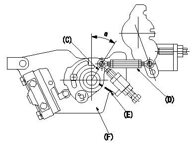
Motor lever adjustment
With the control lever contacting the idle stopper bolt, adjust the length of the rod so that the stepping motor bracket and the motor lever position alignment stamping are aligned.
Nut tightening torque: T1
C:Motor lever
D:Rod
E:Angle aligning stamping position
F:Stepping motor bracket (shape may differ)
----------
T1=3.4~4.9N-m(0.35~0.5kgf-m)
----------
a=(30+-1deg)
----------
T1=3.4~4.9N-m(0.35~0.5kgf-m)
----------
a=(30+-1deg)
0000001901 CAM LEVER ADJUSTMENT
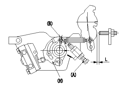
Cam lever adjustment
1. First, loosen the cam stopper bolt (A).
2. Insert a shim (B) between the cam lever and the cam stopper bolt and tighten (A) with shim L inserted. Fix (A) in the position where the idle stopper side shim is loosened.
Nut tightening torque: T2
L1 is lever idle stopper gap measured at partial characteristics.
(A) Cam stopper bolt
(B) Shim
(H) Cam lever
----------
T2=6~9N-m(0.6~0.9kgf-m)
----------
----------
T2=6~9N-m(0.6~0.9kgf-m)
----------
0000002001 IDLE POSITION ADJUSTMENT
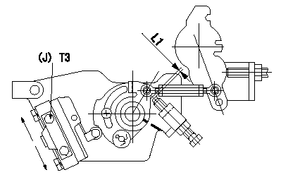
Idle position adjustment
1. Insert a shim L1 between the cam lever and the stopper screw.
2. Move the microswitch in the direction of the arrow so that it turns ON.
3. Turn the microswitch in the direction of the arrow and fix it using the bolts when it turns OFF.
(J) Microswitch fixing bolt
----------
L1=2.1mm
----------
T3=2.0~2.9N-m(0.2~0.3kgf-m)
----------
L1=2.1mm
----------
T3=2.0~2.9N-m(0.2~0.3kgf-m)
0000002101 FULL POSITION ADJUSTMENT
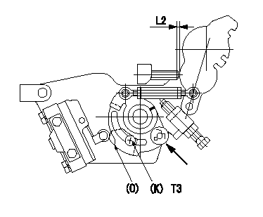
Full position adjustment
(Turn the tension spring pin above the cam lever (in the direction of the arrow) and perform the adjustments below.)
1. Insert a shim L2 between the control lever and the full stopper bolt.
2. Turn the plate clockwise and turn the microswitch ON.
3. Turn the plate counter clockwise and fix it when the microswitch turns OFF.
(K) Bolts (2 locations)
(O) Plate
----------
L2=0.7mm
----------
L2=0.7mm T3=2.0~2.9N-m(0.2~0.3kgf-m)
----------
L2=0.7mm
----------
L2=0.7mm T3=2.0~2.9N-m(0.2~0.3kgf-m)
0000002201 W-CSD ADJUSTMENT
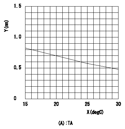
Adjustment of the W-CSD
Adjustment of the timer advance angle
1. Determine the timer advance angle using the graph.
2. Adjust with the screw so that the timer advance angle determined in item 1 is obtained.
X = temperature t (deg C)
Y = timer stroke TA (mm)
(A) = timer stroke
----------
----------
TA=TA=-0.0235t+1.17
----------
----------
TA=TA=-0.0235t+1.17
0000002301 PARTIAL SETTING
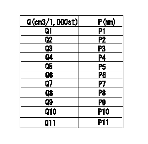
Partial setting
At Np = N1, insert a shim L1 between the control lever and the idle stopper and measure the injection quantity.
Determine the cam lever adjusting shim thickness L for the injection quantity classification in the table.
Q = injection quantity
P = shim thickness at exterior
----------
N1=850r/min L1=5.0mm
----------
Q1=18.5~19.1cm3/1000st Q2=17.8~18.4cm3/1000st Q3=17.2~17.7cm3/1000st Q4=16.5~17.1cm3/1000st Q5=15.8~16.4cm3/1000st Q6=15.1~15.7cm3/1000st Q7=14.3~15.0cm3/1000st Q8=13.6~14.2cm3/1000st Q9=12.8~13.5cm3/1000st Q10=12.0~12.7cm3/1000st Q11=11.3~11.9cm3/1000st P1=4.5mm P2=4.6mm P3=4.7mm P4=4.8mm P5=4.9mm P6=5.0mm P7=5.1mm P8=5.2mm P9=5.3mm P10=5.4mm P11=5.5mm
----------
N1=850r/min L1=5.0mm
----------
Q1=18.5~19.1cm3/1000st Q2=17.8~18.4cm3/1000st Q3=17.2~17.7cm3/1000st Q4=16.5~17.1cm3/1000st Q5=15.8~16.4cm3/1000st Q6=15.1~15.7cm3/1000st Q7=14.3~15.0cm3/1000st Q8=13.6~14.2cm3/1000st Q9=12.8~13.5cm3/1000st Q10=12.0~12.7cm3/1000st Q11=11.3~11.9cm3/1000st P1=4.5mm P2=4.6mm P3=4.7mm P4=4.8mm P5=4.9mm P6=5.0mm P7=5.1mm P8=5.2mm P9=5.3mm P10=5.4mm P11=5.5mm
Information:
Caterpillar: Confidential Yellow
OPTIONAL:IMPROVED FUEL TRANSFER PUMP SEALS FOR COLD WEATHER OPERATION; CHECK FOR NOZZLE GAS LEAKAGE - 3406B IN ALL APP LICATIONS - PI7090 - MAILED US AND CANADA, CACO, COFA, BRAZIL, CFEL, COSA, TRUCK, MARINE & AGRICULTURE TEPS
The information supplied in this service letter may not be valid after the termination date of this program. Do not perform the work outlined in this Service Letter after the termination date without first contacting your Caterpillar product analyst.
IMPROVED FUEL TRANSFER PUMP VALVES FOR COLD WEATHER OPERATION; CHECK FOR NOZZLE GAS LEAKAGE, 3406B Truck, Marine, And Industrial Engines; 3406B Generator Sets; 16G Motor Graders; 245 Excavators And Front Shovels; 824C Tractors; 825C, 826C Compactors; 980C Loaders, 1254, 1256, 1250, PI7090 U-56 A-36 AU-47 B-21 C-51 E-34 O-42 TT-3 TA-3 TM-4 optional parts stock action needed If you received the January 6, 1984 Safety Service Letter (PI1019) and/or the December 2, 1983 Service Letter (PI7049), do all three PIP's at the same time. Problems ****Transfer Pump Valves**** The fuel transfer pump on the above engines has three 1W6182 Valve Assemblies. The one valve in the piston can break in extremely cold weather due to excessive restriction from jelled fuel. Some damage can also occur to the other valve assemblies. A new valve with less flow restriction is now used in the piston and at the other two locations in the pump. These valves are directly adaptable to earlier engines. ****Combustion Gas Leakage Around Fuel Nozzles**** There is a possibility that combustion gases can escape by a fuel injection nozzle and into the adapter. The high temperatures soften the end of the nozzle body and cause the tip to come off. The usual cause for escaping combustion gases is either a loose nozzle in the adapter or a cut in the carbon dam (gas seal). See Illustration 1. Nozzle hold down clamps are all now tightened properly, and an improved chamfer is machined inside the bottom of the adapters to prevent cutting the carbon dam. ILLUSTRATION 1 (SEE ILLUSTRATION) Affected Models And Parts Needed Some of the following vehicles contain the 3406 Engine with the former scroll fuel system and are not in this Program. PIN's (Product Identification No.) Or Serial No. Model Both Problems Gas Leakage Only 3406B Truck Engine 7FB1-8348 8349 - 10145 3406B Marine Engine 4TB1-383 384 - 396 3406B Industrial Engine 6TB1-1184 1185 - 1276 3406B Generator Set 2WB1-1044 1045 - 1166 16G Motor Grader 93U2284-93U2417 93U2418-93U2432 245 Excavator 95V1084-95V1111 95V1112-95V1116 245 Excavator
Have questions with 104749-6650?
Group cross 104749-6650 ZEXEL
Isuzu
104749-6650
9 460 615 031
8944464030
INJECTION-PUMP ASSEMBLY
4EC1
4EC1