Information injection-pump assembly
ZEXEL
104749-6170
1047496170
ISUZU
8941782620
8941782620

Rating:
Cross reference number
ZEXEL
104749-6170
1047496170
ISUZU
8941782620
8941782620
Zexel num
Bosch num
Firm num
Name
104749-6170
8941782620 ISUZU
INJECTION-PUMP ASSEMBLY
4FC1J *
4FC1J *
Calibration Data:
Adjustment conditions
Test oil
1404 Test oil ISO4113orSAEJ967d
1404 Test oil ISO4113orSAEJ967d
Test oil temperature
degC
45
45
50
Nozzle
105000-2010
Bosch type code
NP-DN12SD12TT
Nozzle holder
105780-2080
Opening pressure
MPa
14.7
14.7
15.19
Opening pressure
kgf/cm2
150
150
155
Injection pipe
Inside diameter - outside diameter - length (mm) mm 2-6-840
Inside diameter - outside diameter - length (mm) mm 2-6-840
Transfer pump pressure
kPa
20
20
20
Transfer pump pressure
kgf/cm2
0.2
0.2
0.2
Direction of rotation (viewed from drive side)
Right R
Right R
Injection timing adjustment
Pump speed
r/min
1250
1250
1250
Average injection quantity
mm3/st.
38.1
37.6
38.6
Difference in delivery
mm3/st.
3
Basic
*
Oil temperature
degC
50
48
52
Injection timing adjustment_02
Pump speed
r/min
600
600
600
Average injection quantity
mm3/st.
36.6
35.1
38.1
Oil temperature
degC
50
48
52
Injection timing adjustment_03
Pump speed
r/min
1250
1250
1250
Average injection quantity
mm3/st.
38.1
37.1
39.1
Difference in delivery
mm3/st.
3
Basic
*
Oil temperature
degC
50
48
52
Injection timing adjustment_04
Pump speed
r/min
2000
2000
2000
Average injection quantity
mm3/st.
34.1
32.6
35.6
Oil temperature
degC
50
48
52
Injection timing adjustment_05
Pump speed
r/min
2350
2350
2350
Average injection quantity
mm3/st.
34.5
32.9
36.1
Difference in delivery
mm3/st.
4.5
Oil temperature
degC
52
50
54
Injection quantity adjustment
Pump speed
r/min
2650
2650
2650
Average injection quantity
mm3/st.
11
8
14
Difference in delivery
mm3/st.
3.5
Basic
*
Oil temperature
degC
55
52
58
Injection quantity adjustment_02
Pump speed
r/min
2650
2650
2650
Average injection quantity
mm3/st.
11
8
14
Difference in delivery
mm3/st.
3.5
Oil temperature
degC
55
52
58
Injection quantity adjustment_03
Pump speed
r/min
2800
2800
2800
Average injection quantity
mm3/st.
5
Oil temperature
degC
55
52
58
Governor adjustment
Pump speed
r/min
375
375
375
Average injection quantity
mm3/st.
7.5
5.5
9.5
Difference in delivery
mm3/st.
2
Basic
*
Oil temperature
degC
48
46
50
Governor adjustment_02
Pump speed
r/min
375
375
375
Average injection quantity
mm3/st.
7.5
5.5
9.5
Difference in delivery
mm3/st.
2
Oil temperature
degC
48
46
50
Boost compensator adjustment
Pump speed
r/min
1200
1200
1200
Average injection quantity
mm3/st.
7.2
5.2
9.2
Difference in delivery
mm3/st.
2
Basic
*
Oil temperature
degC
50
48
52
Timer adjustment
Pump speed
r/min
100
100
100
Average injection quantity
mm3/st.
60
60
Basic
*
Oil temperature
degC
48
46
50
Remarks
Full
Full
Timer adjustment_02
Pump speed
r/min
100
100
100
Average injection quantity
mm3/st.
60
60
Oil temperature
degC
48
46
50
Speed control lever angle
Pump speed
r/min
375
375
375
Average injection quantity
mm3/st.
0
0
0
Oil temperature
degC
48
46
50
Remarks
Magnet OFF at idling position
Magnet OFF at idling position
0000000901
Pump speed
r/min
1250
1250
1250
Overflow quantity
cm3/min
420
290
550
Oil temperature
degC
50
48
52
Stop lever angle
Pump speed
r/min
1250
1250
1250
Pressure
kPa
431
411
451
Pressure
kgf/cm2
4.4
4.2
4.6
Basic
*
Oil temperature
degC
50
48
52
Stop lever angle_02
Pump speed
r/min
1250
1250
1250
Pressure
kPa
431
411
451
Pressure
kgf/cm2
4.4
4.2
4.6
Basic
*
Oil temperature
degC
50
48
52
Stop lever angle_03
Pump speed
r/min
2000
2000
2000
Pressure
kPa
647
618
676
Pressure
kgf/cm2
6.6
6.3
6.9
Oil temperature
degC
50
48
52
Stop lever angle_04
Pump speed
r/min
2250
2250
2250
Pressure
kPa
716
687
745
Pressure
kgf/cm2
7.3
7
7.6
Oil temperature
degC
52
50
54
0000001101
Pump speed
r/min
1250
1250
1250
Timer stroke
mm
3
2.8
3.2
Basic
*
Oil temperature
degC
50
48
52
_02
Pump speed
r/min
670
570
770
Timer stroke
mm
0.5
0.5
0.5
Oil temperature
degC
50
48
52
_03
Pump speed
r/min
1250
1250
1250
Timer stroke
mm
3
2.8
3.2
Basic
*
Oil temperature
degC
50
48
52
_04
Pump speed
r/min
2000
2000
2000
Timer stroke
mm
6.3
5.9
6.7
Oil temperature
degC
50
48
52
_05
Pump speed
r/min
2250
2250
2250
Timer stroke
mm
7.4
7.1
7.8
Oil temperature
degC
52
50
54
0000001201
Max. applied voltage
V
8
8
8
Test voltage
V
13
12
14
0000001401
Pump speed
r/min
1250
1250
1250
Average injection quantity
mm3/st.
29
28
30
Timer stroke TA
mm
2.4
2.4
2.4
Timer stroke variation dT
mm
0.6
0.4
0.8
Basic
*
Oil temperature
degC
50
48
52
_02
Pump speed
r/min
1250
1250
1250
Average injection quantity
mm3/st.
29
28
30
Timer stroke variation dT
mm
0.6
0.2
1
Basic
*
Oil temperature
degC
50
48
52
_03
Pump speed
r/min
1250
1250
1250
Average injection quantity
mm3/st.
24
23
25
Timer stroke variation dT
mm
1.3
0.9
1.7
Oil temperature
degC
50
48
52
Timing setting
K dimension
mm
3.3
3.2
3.4
KF dimension
mm
5.8
5.7
5.9
MS dimension
mm
1.6
1.5
1.7
Control lever angle alpha
deg.
20
16
24
Control lever angle beta
deg.
33.5
28.5
38.5
Test data Ex:
0000001801 MICROSWITCH ADJUSTMENT
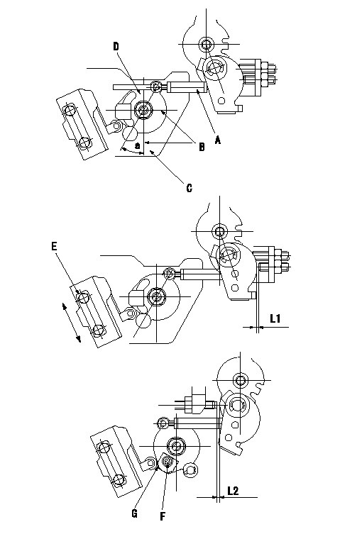
Microswitch adjustment
Stepping motor adjustment
1. With the sub-lever and the control lever contacting the idle stopper bolt, adjust the length of the rod so that the stepping motor bracket and the stepping motor lever aligning mark are aligned (Tightening torque T).
A = rod
B = position of angle alignment marking
C = stepping motor bracket
D = stepping motor lever
2. Idle position adjustment
1) Fix so that idle stopper contacts the control lever.
2) Insert shim L1 between the sub-lever and the idle stopper.
3) Move the microswitch in the direction of the arrow to turn it ON.
4) Move the microswitch in the direction of the arrow and fix it where it turns OFF using the microswitch fixing bolt.
E = microswitch fixing bolt (Tightening torque T2)
3. Full position adjustment
1) 1) Fix so that sub lever contacts the control lever.
2) Insert a shim L2 between the control lever and the full stopper.
3) Turn the plate clockwise as shown in the figure above and confirm that the microswitch turns ON.
4) Move the plate counterclockwise and fix it where the microswitch turns OFF.
F = bolt (Tightening torque T2)
G = plate
----------
L1=1.2mm L2=0.7mm T1=3.4~4.9N-m(0.35~0.5kgf-m) T2=2.0~2.9N-m(0.2~0.3kgf-m)
----------
a=30+-1deg L1=1.2mm L2=0.7mm
----------
L1=1.2mm L2=0.7mm T1=3.4~4.9N-m(0.35~0.5kgf-m) T2=2.0~2.9N-m(0.2~0.3kgf-m)
----------
a=30+-1deg L1=1.2mm L2=0.7mm
0000001901 PARTIAL SETTING
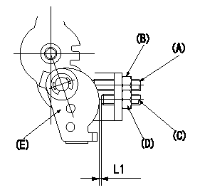
Partial injection quantity adjustment
(A) Stopper bolt
(B) Fixed nut
(C) Sub lever stopper bolt
(D) Fixed nut
(E) Sub lever
1. At pump speed N1, adjust the stopper bolt (A) so that the idle injection quantity is Q1. Then fix using the nut (B).
2. Confirm that the idle injection quantity is Q2 when the pump speed is N2.
3. Insert a shim L1 between the sub lever (E) and the sub lever stopper bolt (C). Adjust the sub lever stopper bolt so that the injection quantity is Q3 at pump speed N3 and fix using the nut.
----------
N1=375r/min N2=450r/min N3=1200r/min Q1=7.5+-2.0mm3/st Q2=3--mm3/st Q3=(7.2+-1mm3/st) L1=9.5+-0.1mm
----------
L1=9.5+-0.1mm
----------
N1=375r/min N2=450r/min N3=1200r/min Q1=7.5+-2.0mm3/st Q2=3--mm3/st Q3=(7.2+-1mm3/st) L1=9.5+-0.1mm
----------
L1=9.5+-0.1mm
Information:
In this manual, specifications, service standards, adjustment procedures, disassembly procedures, inspection procedures, and reassembly procedures for the engine are shown in groups. The contents of each group are listed in the index and at the beginning of that group. For instructions on operation and periodic inspection, refer to the operation manual. For instructions on ordering replacement parts, refer to the parts catalog. For information on the engine's structure and function, refer to relevant training material.Items Shown in this Manual
(1) Parts mentioned in the text and shown exploded views are numbered in their disassembly sequences.(2) Inspections to be preformed during disassembly are shown in
in the exploded views.(3) Service standards for inspection and repair operations are indicated at relevant places in the text and in a table in Group 2.(4) The sequences in which parts should be reassembled during reassembly operations are shown under reassembly drawings in this manner:
(5) The symbols and headings shown below are used in this manual to highlight particularly important and safety-critical instruction.
Indicates a potentially hazardous situation which, if not avoided, can result in death or serious injury.
Indicates a potentially hazardous situation which, if not avoided, can result in minor or moderate injury.
Indicates a potentially hazardous situation which, if not avoided, can result in property damage.
Indicates important information or information which is useful for engine operation or maintenance.(6) With regard to tightening torques, points to which engine oil must be applied are labeled "Wet". Where there is no such indication, parts should be tightened in a dry condition.Terms Used in This Manual
Terms used in this manual are defined as follows:(1) Front and RearThe term "front" refers to the fan side of the engine, and the term "rear" applies to the flywheel side.(2) Left and RightThe term "left" and "right" apply to the sides of the engine as seen from the flywheel.(3) Service Standards* Standard ValueThis term indicates a designed nominal dimension, the designed dimension of a single part, the standard clearance between two parts after assembly, or a standard performance value for an assembly.* LimitThis term indicates a value beyond which a part is no longer usable in terms of performance and strength and must be repaired or replaced.
Have questions with 104749-6170?
Group cross 104749-6170 ZEXEL
Isuzu
104749-6170
8941782620
INJECTION-PUMP ASSEMBLY
4FC1J
4FC1J