Information injection-pump assembly
ZEXEL
104749-6160
1047496160
ISUZU
8941782700
8941782700

Rating:
Cross reference number
ZEXEL
104749-6160
1047496160
ISUZU
8941782700
8941782700
Zexel num
Bosch num
Firm num
Name
104749-6160
8941782700 ISUZU
INJECTION-PUMP ASSEMBLY
4FC1-J *
4FC1-J *
Calibration Data:
Adjustment conditions
Test oil
1404 Test oil ISO4113orSAEJ967d
1404 Test oil ISO4113orSAEJ967d
Test oil temperature
degC
45
45
50
Nozzle
105000-2010
Bosch type code
NP-DN12SD12TT
Nozzle holder
105780-2080
Opening pressure
MPa
14.7
14.7
15.19
Opening pressure
kgf/cm2
150
150
155
Injection pipe
Inside diameter - outside diameter - length (mm) mm 2-6-840
Inside diameter - outside diameter - length (mm) mm 2-6-840
Transfer pump pressure
kPa
20
20
20
Transfer pump pressure
kgf/cm2
0.2
0.2
0.2
Direction of rotation (viewed from drive side)
Right R
Right R
Injection timing adjustment
Pump speed
r/min
1250
1250
1250
Average injection quantity
mm3/st.
36.2
35.7
36.7
Difference in delivery
mm3/st.
3
Basic
*
Oil temperature
degC
50
48
52
Injection timing adjustment_02
Pump speed
r/min
600
600
600
Average injection quantity
mm3/st.
34.7
33.2
36.2
Oil temperature
degC
50
48
52
Injection timing adjustment_03
Pump speed
r/min
1250
1250
1250
Average injection quantity
mm3/st.
36.2
35.2
37.2
Difference in delivery
mm3/st.
3
Basic
*
Oil temperature
degC
50
48
52
Injection timing adjustment_04
Pump speed
r/min
2000
2000
2000
Average injection quantity
mm3/st.
32.2
30.7
33.7
Oil temperature
degC
50
48
52
Injection timing adjustment_05
Pump speed
r/min
2350
2350
2350
Average injection quantity
mm3/st.
32.6
31
34.2
Difference in delivery
mm3/st.
4
Oil temperature
degC
52
50
54
Injection quantity adjustment
Pump speed
r/min
2650
2650
2650
Average injection quantity
mm3/st.
11
8
14
Difference in delivery
mm3/st.
3.5
Basic
*
Oil temperature
degC
55
52
58
Injection quantity adjustment_02
Pump speed
r/min
2650
2650
2650
Average injection quantity
mm3/st.
11
8
14
Difference in delivery
mm3/st.
3.5
Oil temperature
degC
55
52
58
Injection quantity adjustment_03
Pump speed
r/min
2800
2800
2800
Average injection quantity
mm3/st.
5
Oil temperature
degC
55
52
58
Governor adjustment
Pump speed
r/min
400
400
400
Average injection quantity
mm3/st.
7.5
5.5
9.5
Difference in delivery
mm3/st.
2
Basic
*
Oil temperature
degC
48
46
50
Governor adjustment_02
Pump speed
r/min
400
400
400
Average injection quantity
mm3/st.
7.5
5.5
9.5
Difference in delivery
mm3/st.
2
Oil temperature
degC
48
46
50
Timer adjustment
Pump speed
r/min
100
100
100
Average injection quantity
mm3/st.
60
60
Basic
*
Oil temperature
degC
48
46
50
Remarks
Full
Full
Timer adjustment_02
Pump speed
r/min
100
100
100
Average injection quantity
mm3/st.
60
60
Oil temperature
degC
48
46
50
Speed control lever angle
Pump speed
r/min
400
400
400
Average injection quantity
mm3/st.
0
0
0
Oil temperature
degC
48
46
50
Remarks
Magnet OFF at idling position
Magnet OFF at idling position
0000000901
Pump speed
r/min
1250
1250
1250
Overflow quantity
cm3/min
420
290
550
Oil temperature
degC
50
48
52
Stop lever angle
Pump speed
r/min
1250
1250
1250
Pressure
kPa
431
411
451
Pressure
kgf/cm2
4.4
4.2
4.6
Basic
*
Oil temperature
degC
50
48
52
Stop lever angle_02
Pump speed
r/min
1250
1250
1250
Pressure
kPa
431
411
451
Pressure
kgf/cm2
4.4
4.2
4.6
Basic
*
Oil temperature
degC
50
48
52
Stop lever angle_03
Pump speed
r/min
2000
2000
2000
Pressure
kPa
647
618
676
Pressure
kgf/cm2
6.6
6.3
6.9
Oil temperature
degC
50
48
52
Stop lever angle_04
Pump speed
r/min
2250
2250
2250
Pressure
kPa
716
687
745
Pressure
kgf/cm2
7.3
7
7.6
Oil temperature
degC
52
50
54
0000001101
Pump speed
r/min
1250
1250
1250
Timer stroke
mm
3
2.8
3.2
Basic
*
Oil temperature
degC
50
48
52
_02
Pump speed
r/min
670
570
770
Timer stroke
mm
0.5
0.5
0.5
Oil temperature
degC
50
48
52
_03
Pump speed
r/min
1250
1250
1250
Timer stroke
mm
3
2.8
3.2
Basic
*
Oil temperature
degC
50
48
52
_04
Pump speed
r/min
2000
2000
2000
Timer stroke
mm
6.3
5.9
6.7
Oil temperature
degC
50
48
52
_05
Pump speed
r/min
2250
2250
2250
Timer stroke
mm
7.4
7.1
7.8
Oil temperature
degC
52
50
54
0000001201
Max. applied voltage
V
8
8
8
Test voltage
V
13
12
14
0000001401
Pump speed
r/min
1250
1250
1250
Average injection quantity
mm3/st.
29
28
30
Timer stroke TA
mm
2.4
2.4
2.4
Timer stroke variation dT
mm
0.6
0.4
0.8
Basic
*
Oil temperature
degC
50
48
52
_02
Pump speed
r/min
1250
1250
1250
Average injection quantity
mm3/st.
29
28
30
Timer stroke variation dT
mm
0.6
0.2
1
Basic
*
Oil temperature
degC
50
48
52
_03
Pump speed
r/min
1250
1250
1250
Average injection quantity
mm3/st.
24
23
25
Timer stroke variation dT
mm
1.3
0.9
1.7
Oil temperature
degC
50
48
52
0000001501
Pump speed
r/min
1250
1250
1250
Height
m
2000
2000
2000
Atmospheric pressure difference
kPa
-21.9
-22.6
-21.2
Atmospheric pressure difference
mmHg
-164
-169
-159
Average injection quantity
mm3/st.
32.6
32.6
32.6
Decrease qty
mm3/st.
3.6
2.6
4.6
Decrease rate
%
10
7
13
Basic
*
Oil temperature
degC
50
48
52
_02
Pump speed
r/min
1250
1250
1250
Height
m
0
0
0
Atmospheric pressure difference
kPa
0
0
0
Atmospheric pressure difference
mmHg
0
0
0
Decrease qty
mm3/st.
0
0
0
Decrease rate
%
0
0
0
Oil temperature
degC
50
48
52
_03
Pump speed
r/min
1250
1250
1250
Height
m
500
500
500
Atmospheric pressure difference
kPa
-5.9
-9.2
-2.6
Atmospheric pressure difference
mmHg
-44
-69
-19
Oil temperature
degC
50
48
52
_04
Pump speed
r/min
1250
1250
1250
Height
m
2000
2000
2000
Atmospheric pressure difference
kPa
-21.9
-22.6
-21.2
Atmospheric pressure difference
mmHg
-164
-169
-159
Decrease qty
mm3/st.
3.6
2.6
4.6
Decrease rate
%
10
7
13
Basic
*
Oil temperature
degC
50
48
52
Timing setting
K dimension
mm
3.3
3.2
3.4
KF dimension
mm
5.8
5.7
5.9
MS dimension
mm
1.6
1.5
1.7
Control lever angle alpha
deg.
24.5
20.5
28.5
Control lever angle beta
deg.
45
40
50
Test data Ex:
0000001801 MICROSWITCH ADJUSTMENT
Microswitch adjustment
With the control lever 'a' from the idle position (idle stopper lever clearance L), adjust the position of the microswitch and fix it in the position where it goes OFF.
After adjustment, the microswitch must not turn OFF at lever position between idle and a.
Also, the microswitch lever must not contact the stopper.
----------
a=26+-1deg L=8.5+-0.2mm
----------
----------
a=26+-1deg L=8.5+-0.2mm
----------
0000001901 W-CSD ADJUSTMENT
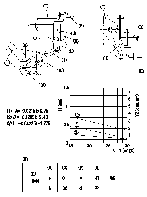
Adjustment of the W-CSD
1. Adjustment of the timer stroke
Adjust screw (A) so that the timer stroke is the value determined from the graph.
2. Adjustment of the position of the intermediate lever.
(1)Insert a shim L1 between the control lever (F) and the idle set screw (G).
(2)Set intermediate lever (D) adjusting screw (E) so that adjusting screw (E) contacts control lever, and so that when intermediate lever is at right angles to pump center, intermediate lever and idle stopper bracket (H) overlap at position (J).
3. W-CSD adjustment
Insert a shim L1+-0.05 between the control lever (F) and the idle set screw (G).
Use adjusting screw (B) to fix the CSD lever (C) in the position where it operates the intermediate lever (D) via the rod (I).
X:Temperature t (deg C)
Y1:Timer stroke TA (mm)
Y2:Control lever position at theta L (deg, mm)
(W) Cold advancer
(R) Cooling water temperature (deg C)
(S) Cooling water temperature: increase direction
(O) Timer piston stroke (mm)
(P) Lever position (deg)
(Q) lever position (mm)
(M) standard point
N:Pump speed
----------
L1=0.93+-0.05mm
----------
N1=500r/min a=20degC b=-20degC c=2.9+-1deg d=8+-3deg O1=0.3+-0.4mm O2=1.2+-0.6mm Q1=0.93+-0.3mm Q2=2.62+-1mm
----------
L1=0.93+-0.05mm
----------
N1=500r/min a=20degC b=-20degC c=2.9+-1deg d=8+-3deg O1=0.3+-0.4mm O2=1.2+-0.6mm Q1=0.93+-0.3mm Q2=2.62+-1mm
Information:
An additional 5 hours is allowed if the harness must replaced.
Product smu/age whichever comes first Caterpillar Dealer Suggested Customer Suggested
Parts % Labor Hrs% Parts % Labor Hrs% Parts % Labor Hrs%
*******Group 2*******
0-4000 hrs,
0-12 mo 100.0% 100.0% 0.0% 0.0% 0.0% 0.0%
This is a 3.0-hour job for Group 2
An additional 10 hours is allowed if the harness must replaced.
PARTS DISPOSITION
Handle the parts in accordance with your Warranty Bulletin on warranty parts handling.
Rework Procedure
Group Number 1
Injector Harness Inspection
-Raise the engine enclosure hood.
-Remove the air intake pipe connecting the air filter to the turbo inlet.
-Remove the valve covers.
-Inspect the injector harness wiring for contact between the harness and valve springs.
Image1.1.1
Repair
-If the harness is close to the valve spring, adjust the harness by disconnecting the injector connector rotating the connector 360 degrees and reconnecting it. This should slightly twist the wires and pull them away from the springs.
Image1.2.1
Injector Harness Replacement (If Necessary)
-If the injector harness has contacted the spring and cut the wire or exposed the wire, then replace the injector harness that is under the valve cover.
-When installing the new harness to the valve cover base make sure the tabs do not turn while torquing down the bolts(see the picture below). Keep the tabs straight, and this will help keep the wiring away from the valve springs.
Image1.3.1
Group Number 2
Injector Harness Inspection
-Remove the rear engine enclosure.
-Remove the clamp for flex boot on the air filter housing.
-Remove the rubber elbow on the inlet of the compressor side of the turbocharger.
-Remove the clamps called out in the photo for the turbocharger outlet pipe that connects to the aftercooler.
Image2.1.1
-Remove all three engine valve covers.
-Inspect the injector harness wiring for contact between the harness and valve springs.
Image2.2.1
Repair
-If the harness is close to the valve spring, adjust the harness by disconnecting the injector connector rotating the connector 360 degrees and reconnecting it. This should slightly twist the wires and pull them away from the springs.
Image2.3.1
Injector Harness Replacement (If Necessary)
-If the injector harness has contacted the spring and cut the wire or exposed the wire, then replace the injector harness that is under the valve cover.
-Remove the doors, hood, Clean Emissions Module (CEM) and mounting plate, and valve cover base.
-When installing the new harness to the valve cover base make sure the tabs do not turn while torquing down the bolts(see the picture below). Keep the tabs straight, and this will help keep the wiring away from the valve springs.
Image2.4.1
-Reinstall the previously removed hardware, and use the new 344-8311 exhaust clamp.
Image2.5.1
Have questions with 104749-6160?
Group cross 104749-6160 ZEXEL
Isuzu
104749-6160
8941782700
INJECTION-PUMP ASSEMBLY
4FC1-J
4FC1-J