Information injection-pump assembly
ZEXEL
104749-6140
1047496140
ISUZU
8941782610
8941782610

Rating:
Cross reference number
ZEXEL
104749-6140
1047496140
ISUZU
8941782610
8941782610
Zexel num
Bosch num
Firm num
Name
104749-6140
8941782610 ISUZU
INJECTION-PUMP ASSEMBLY
4FC1-J *
4FC1-J *
Calibration Data:
Adjustment conditions
Test oil
1404 Test oil ISO4113orSAEJ967d
1404 Test oil ISO4113orSAEJ967d
Test oil temperature
degC
45
45
50
Nozzle
105000-2010
Bosch type code
NP-DN12SD12TT
Nozzle holder
105780-2080
Opening pressure
MPa
14.7
14.7
15.19
Opening pressure
kgf/cm2
150
150
155
Injection pipe
Inside diameter - outside diameter - length (mm) mm 2-6-840
Inside diameter - outside diameter - length (mm) mm 2-6-840
Transfer pump pressure
kPa
20
20
20
Transfer pump pressure
kgf/cm2
0.2
0.2
0.2
Direction of rotation (viewed from drive side)
Right R
Right R
Injection timing adjustment
Pump speed
r/min
1250
1250
1250
Average injection quantity
mm3/st.
38.1
37.6
38.6
Difference in delivery
mm3/st.
3
Basic
*
Oil temperature
degC
50
48
52
Injection timing adjustment_02
Pump speed
r/min
600
600
600
Average injection quantity
mm3/st.
36.6
35.1
38.1
Oil temperature
degC
50
48
52
Injection timing adjustment_03
Pump speed
r/min
1250
1250
1250
Average injection quantity
mm3/st.
38.1
37.1
39.1
Difference in delivery
mm3/st.
3
Basic
*
Oil temperature
degC
50
48
52
Injection timing adjustment_04
Pump speed
r/min
2000
2000
2000
Average injection quantity
mm3/st.
34.1
32.6
35.6
Oil temperature
degC
50
48
52
Injection timing adjustment_05
Pump speed
r/min
2350
2350
2350
Average injection quantity
mm3/st.
34.5
32.9
36.1
Difference in delivery
mm3/st.
4.5
Oil temperature
degC
52
50
54
Injection quantity adjustment
Pump speed
r/min
2650
2650
2650
Average injection quantity
mm3/st.
11
8
14
Difference in delivery
mm3/st.
3.5
Basic
*
Oil temperature
degC
55
52
58
Injection quantity adjustment_02
Pump speed
r/min
2650
2650
2650
Average injection quantity
mm3/st.
11
8
14
Difference in delivery
mm3/st.
3.5
Oil temperature
degC
55
52
58
Injection quantity adjustment_03
Pump speed
r/min
2800
2800
2800
Average injection quantity
mm3/st.
5
Oil temperature
degC
55
52
58
Governor adjustment
Pump speed
r/min
400
400
400
Average injection quantity
mm3/st.
7.5
5.5
9.5
Difference in delivery
mm3/st.
2
Basic
*
Oil temperature
degC
48
46
50
Governor adjustment_02
Pump speed
r/min
400
400
400
Average injection quantity
mm3/st.
7.5
5.5
9.5
Difference in delivery
mm3/st.
2
Oil temperature
degC
48
46
50
Timer adjustment
Pump speed
r/min
100
100
100
Average injection quantity
mm3/st.
60
60
Basic
*
Oil temperature
degC
48
46
50
Remarks
Full
Full
Timer adjustment_02
Pump speed
r/min
100
100
100
Average injection quantity
mm3/st.
60
60
Oil temperature
degC
48
46
50
Speed control lever angle
Pump speed
r/min
400
400
400
Average injection quantity
mm3/st.
0
0
0
Oil temperature
degC
48
46
50
Remarks
Magnet OFF at idling position
Magnet OFF at idling position
0000000901
Pump speed
r/min
1250
1250
1250
Overflow quantity
cm3/min
420
290
550
Oil temperature
degC
50
48
52
Stop lever angle
Pump speed
r/min
1250
1250
1250
Pressure
kPa
431
411
451
Pressure
kgf/cm2
4.4
4.2
4.6
Basic
*
Oil temperature
degC
50
48
52
Stop lever angle_02
Pump speed
r/min
1250
1250
1250
Pressure
kPa
431
411
451
Pressure
kgf/cm2
4.4
4.2
4.6
Basic
*
Oil temperature
degC
50
48
52
Stop lever angle_03
Pump speed
r/min
2000
2000
2000
Pressure
kPa
647
618
676
Pressure
kgf/cm2
6.6
6.3
6.9
Oil temperature
degC
50
48
52
Stop lever angle_04
Pump speed
r/min
2250
2250
2250
Pressure
kPa
716
687
745
Pressure
kgf/cm2
7.3
7
7.6
Oil temperature
degC
52
50
54
0000001101
Pump speed
r/min
1250
1250
1250
Timer stroke
mm
3
2.8
3.2
Basic
*
Oil temperature
degC
50
48
52
_02
Pump speed
r/min
670
570
770
Timer stroke
mm
0.5
0.5
0.5
Oil temperature
degC
50
48
52
_03
Pump speed
r/min
1250
1250
1250
Timer stroke
mm
3
2.8
3.2
Basic
*
Oil temperature
degC
50
48
52
_04
Pump speed
r/min
2000
2000
2000
Timer stroke
mm
6.3
5.9
6.7
Oil temperature
degC
50
48
52
_05
Pump speed
r/min
2250
2250
2250
Timer stroke
mm
7.4
7.1
7.8
Oil temperature
degC
52
50
54
0000001201
Max. applied voltage
V
8
8
8
Test voltage
V
13
12
14
0000001401
Pump speed
r/min
1250
1250
1250
Average injection quantity
mm3/st.
29
28
30
Timer stroke TA
mm
2.4
2.4
2.4
Timer stroke variation dT
mm
0.6
0.4
0.8
Basic
*
Oil temperature
degC
50
48
52
_02
Pump speed
r/min
1250
1250
1250
Average injection quantity
mm3/st.
29
28
30
Timer stroke variation dT
mm
0.6
0.2
1
Basic
*
Oil temperature
degC
50
48
52
_03
Pump speed
r/min
1250
1250
1250
Average injection quantity
mm3/st.
24
23
25
Timer stroke variation dT
mm
1.3
0.9
1.7
Oil temperature
degC
50
48
52
Timing setting
K dimension
mm
3.3
3.2
3.4
KF dimension
mm
5.8
5.7
5.9
MS dimension
mm
1.6
1.5
1.7
Control lever angle alpha
deg.
24.5
20.5
28.5
Control lever angle beta
deg.
45
40
50
Test data Ex:
0000001801 MICROSWITCH ADJUSTMENT
Microswitch adjustment
With the control lever 'a' from the idle position (idle stopper lever clearance L), adjust the position of the microswitch and fix it in the position where it goes OFF.
After adjustment, the microswitch must not turn OFF at lever position between idle and a.
Also, the microswitch lever must not contact the stopper.
----------
a=26+-1deg L=8.5+-0.2mm
----------
----------
a=26+-1deg L=8.5+-0.2mm
----------
0000001901 W-CSD ADJUSTMENT
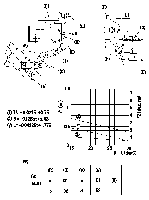
Adjustment of the W-CSD
1. Adjustment of the timer stroke
Adjust screw (A) so that the timer stroke is the value determined from the graph.
2. Adjustment of the position of the intermediate lever.
(1)Insert a shim L1 between the control lever (F) and the idle set screw (G).
(2)Set intermediate lever (D) adjusting screw (E) so that adjusting screw (E) contacts control lever, and so that when intermediate lever is at right angles to pump center, intermediate lever and idle stopper bracket (H) overlap at position (J).
3. W-CSD adjustment
Insert a shim L1+-0.05 between the control lever (F) and the idle set screw (G).
Use adjusting screw (B) to fix the CSD lever (C) in the position where it operates the intermediate lever (D) via the rod (I).
X:Temperature t (deg C)
Y1:Timer stroke TA (mm)
Y2:Control lever position at theta L (deg, mm)
(W) Cold advancer
(R) Cooling water temperature (deg C)
(S) Cooling water temperature: increase direction
(O) Timer piston stroke (mm)
(P) Lever position (deg)
(Q) lever position (mm)
(M) standard point
N:Pump speed
----------
L1=0.93+-0.05mm
----------
N1=500r/min a=20degC b=-20degC c=2.9+-1deg d=8+-3deg O1=0.3+-0.4mm O2=1.2+-0.6mm Q1=0.93+-0.3mm Q2=2.62+-1mm
----------
L1=0.93+-0.05mm
----------
N1=500r/min a=20degC b=-20degC c=2.9+-1deg d=8+-3deg O1=0.3+-0.4mm O2=1.2+-0.6mm Q1=0.93+-0.3mm Q2=2.62+-1mm
Information:
Disassembling alternator(2) Removing Pulley(a) Wrap cloth around the rotor, then clamp the rotor in a vise. Remove the pulley nut and then the pulley and spacer.(b) Pull the rotor out of the front bracket.
Removing pulley(3) Removing Stator and Rectifier(a) Unsolder from the rectifier the leads that connect the rectifier to the stator coils. Then, remove the stator.
Unsolder the leads quickly to prevent heat from damaging the diodes.
(b) Remove the rectifier's mounting screws, then remove the rectifier.
Removing stator3.4 Inspection KEY POINTS FOR INSPECTION(1) Inspecting RectifierWith each diode, measure the resistance between the diode terminal and the heat sink. Measure the resistance with the tester's (+) probe applied to the diode terminal and with the tester's (-) probe applied to the diode terminal. If the resistance is infinite in both cases, there is an open circuit. If the resistance is close to zero in both cases, there is a short circuit. An open circuit or short circuit indicates a diode fault. Replace the rectifier if any diode is faulty.Next, measure the resistance between the terminals of the leads that connect the rectifier to the stator coil for each of the diodes. If any measurement reveals an open circuit (infinite resistance) or a short circuit (near-zero resistance), replace the rectifier.
Inspecting rectifier(2) Inspecting Field Coil(a) Check whether continuity exists between the rotor's slip rings. If continuity does not exist, the field coil is open-circuited and the rotor must be replaced.
Field coil continuity test(b) Check whether continuity exists between each slip ring and the rotor shaft (or core). If continuity exists, the field coil is grounded and the rotor must be replaced.
Field coil ground test(3) Inspecting Stator Coils(a) Check whether continuity exists between the leads at the ends of each stator coil. If continuity does not exist between any coil's leads, there is an open circuit and the stator must be replaced.
Stator coil continuity test(b) Check whether continuity exists between each stator coil lead and the stator core. If continuity exists, the stator coil is grounded and the stator must be replaced.
Stator coil ground test(4) Inspecting Brushes(a) Replace the brush if it is worn down to the wear limit line.
Inspecting brush(b) To replace the brush, remove the cover (see the drawing) then unsolder and take out the brush set.
Replacing brush3.5 AssemblyPerform assembly by following the disassembly sequence in reverse. KEY POINTS FOR ASSEMBLY(1) Heat the rear bracket before press-fitting the rear bearing into it. Do not apply oil or grease to the outer or inner surface of the bearing.(2) Before fitting the rotor in the rear bracket, insert a thin metal rod into the small hole in the rear bracket to keep the brushes raised. Remove the metal rod when assembly is complete.
Assembling alternator3.6 InstallationPerform installation by following the removal sequence in reverse. KEY POINTS FOR INSTALLATION Insertion of spacer and clearance adjustmentInstallation of the support bolt is accompanied by insertion of a spacer. Install the spacer as follows:(a) Insert the support bolt into pinion. (Do not install the nut.)(b) Install the alternator
Have questions with 104749-6140?
Group cross 104749-6140 ZEXEL
Isuzu
104749-6140
8941782610
INJECTION-PUMP ASSEMBLY
4FC1-J
4FC1-J