Information injection-pump assembly
ZEXEL
104749-6130
1047496130
ISUZU
8941782600
8941782600

Rating:
Cross reference number
ZEXEL
104749-6130
1047496130
ISUZU
8941782600
8941782600
Zexel num
Bosch num
Firm num
Name
104749-6130
8941782600 ISUZU
INJECTION-PUMP ASSEMBLY
4FC1-J *
4FC1-J *
Calibration Data:
Adjustment conditions
Test oil
1404 Test oil ISO4113orSAEJ967d
1404 Test oil ISO4113orSAEJ967d
Test oil temperature
degC
45
45
50
Nozzle
105000-2010
Bosch type code
NP-DN12SD12TT
Nozzle holder
105780-2080
Opening pressure
MPa
14.7
14.7
15.19
Opening pressure
kgf/cm2
150
150
155
Injection pipe
Inside diameter - outside diameter - length (mm) mm 2-6-840
Inside diameter - outside diameter - length (mm) mm 2-6-840
Transfer pump pressure
kPa
20
20
20
Transfer pump pressure
kgf/cm2
0.2
0.2
0.2
Direction of rotation (viewed from drive side)
Right R
Right R
Injection timing adjustment
Pump speed
r/min
1250
1250
1250
Average injection quantity
mm3/st.
38.1
37.6
38.6
Difference in delivery
mm3/st.
3
Basic
*
Oil temperature
degC
50
48
52
Injection timing adjustment_02
Pump speed
r/min
600
600
600
Average injection quantity
mm3/st.
36.6
35.1
38.1
Oil temperature
degC
50
48
52
Injection timing adjustment_03
Pump speed
r/min
1250
1250
1250
Average injection quantity
mm3/st.
38.1
37.1
39.1
Difference in delivery
mm3/st.
3
Basic
*
Oil temperature
degC
50
48
52
Injection timing adjustment_04
Pump speed
r/min
2000
2000
2000
Average injection quantity
mm3/st.
34.1
32.6
35.6
Oil temperature
degC
50
48
52
Injection timing adjustment_05
Pump speed
r/min
2350
2350
2350
Average injection quantity
mm3/st.
34.5
32.9
36.1
Difference in delivery
mm3/st.
4.5
Oil temperature
degC
52
50
54
Injection quantity adjustment
Pump speed
r/min
2650
2650
2650
Average injection quantity
mm3/st.
11
8
14
Difference in delivery
mm3/st.
3.5
Basic
*
Oil temperature
degC
55
52
58
Injection quantity adjustment_02
Pump speed
r/min
2650
2650
2650
Average injection quantity
mm3/st.
11
8
14
Difference in delivery
mm3/st.
3.5
Oil temperature
degC
55
52
58
Injection quantity adjustment_03
Pump speed
r/min
2800
2800
2800
Average injection quantity
mm3/st.
5
Oil temperature
degC
55
52
58
Governor adjustment
Pump speed
r/min
375
375
375
Average injection quantity
mm3/st.
7.5
5.5
9.5
Difference in delivery
mm3/st.
2
Basic
*
Oil temperature
degC
48
46
50
Governor adjustment_02
Pump speed
r/min
375
375
375
Average injection quantity
mm3/st.
7.5
5.5
9.5
Difference in delivery
mm3/st.
2
Oil temperature
degC
48
46
50
Timer adjustment
Pump speed
r/min
100
100
100
Average injection quantity
mm3/st.
60
60
Basic
*
Oil temperature
degC
48
46
50
Remarks
Full
Full
Timer adjustment_02
Pump speed
r/min
100
100
100
Average injection quantity
mm3/st.
60
60
Oil temperature
degC
48
46
50
Speed control lever angle
Pump speed
r/min
375
375
375
Average injection quantity
mm3/st.
0
0
0
Oil temperature
degC
48
46
50
Remarks
Magnet OFF at idling position
Magnet OFF at idling position
0000000901
Pump speed
r/min
1250
1250
1250
Overflow quantity
cm3/min
420
290
550
Oil temperature
degC
50
48
52
Stop lever angle
Pump speed
r/min
1250
1250
1250
Pressure
kPa
431
411
451
Pressure
kgf/cm2
4.4
4.2
4.6
Basic
*
Oil temperature
degC
50
48
52
Stop lever angle_02
Pump speed
r/min
1250
1250
1250
Pressure
kPa
431
411
451
Pressure
kgf/cm2
4.4
4.2
4.6
Basic
*
Oil temperature
degC
50
48
52
Stop lever angle_03
Pump speed
r/min
2000
2000
2000
Pressure
kPa
647
618
676
Pressure
kgf/cm2
6.6
6.3
6.9
Oil temperature
degC
50
48
52
Stop lever angle_04
Pump speed
r/min
2250
2250
2250
Pressure
kPa
716
687
745
Pressure
kgf/cm2
7.3
7
7.6
Oil temperature
degC
52
50
54
0000001101
Pump speed
r/min
1250
1250
1250
Timer stroke
mm
3
2.8
3.2
Basic
*
Oil temperature
degC
50
48
52
_02
Pump speed
r/min
670
570
770
Timer stroke
mm
0.5
0.5
0.5
Oil temperature
degC
50
48
52
_03
Pump speed
r/min
1250
1250
1250
Timer stroke
mm
3
2.8
3.2
Basic
*
Oil temperature
degC
50
48
52
_04
Pump speed
r/min
2000
2000
2000
Timer stroke
mm
6.3
5.9
6.7
Oil temperature
degC
50
48
52
_05
Pump speed
r/min
2250
2250
2250
Timer stroke
mm
7.4
7.1
7.8
Oil temperature
degC
52
50
54
0000001201
Max. applied voltage
V
8
8
8
Test voltage
V
13
12
14
0000001401
Pump speed
r/min
1250
1250
1250
Average injection quantity
mm3/st.
29
28
30
Timer stroke TA
mm
2.4
2.4
2.4
Timer stroke variation dT
mm
0.6
0.4
0.8
Basic
*
Oil temperature
degC
50
48
52
_02
Pump speed
r/min
1250
1250
1250
Average injection quantity
mm3/st.
29
28
30
Timer stroke variation dT
mm
0.6
0.2
1
Basic
*
Oil temperature
degC
50
48
52
_03
Pump speed
r/min
1250
1250
1250
Average injection quantity
mm3/st.
24
23
25
Timer stroke variation dT
mm
1.3
0.9
1.7
Oil temperature
degC
50
48
52
Timing setting
K dimension
mm
3.3
3.2
3.4
KF dimension
mm
5.8
5.7
5.9
MS dimension
mm
1.6
1.5
1.7
Control lever angle alpha
deg.
24.5
20.5
28.5
Control lever angle beta
deg.
40.5
35.5
45.5
Test data Ex:
0000001801 W-CSD ADJUSTMENT
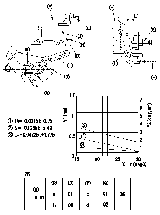
Adjustment of the W-CSD
1. Adjustment of the timer stroke
Adjust screw (A) so that the timer stroke is the value determined from the graph.
2. Adjustment of the position of the intermediate lever.
(1)Insert a shim L1 between the control lever (F) and the idle set screw (G).
(2)Set intermediate lever (D) adjusting screw (E) so that adjusting screw (E) contacts control lever, and so that when intermediate lever is at right angles to pump center, intermediate lever and idle stopper bracket (H) overlap at position (J).
3. W-CSD adjustment
Insert a shim L1+-0.05 between the control lever (F) and the idle set screw (G).
Use adjusting screw (B) to fix the CSD lever (C) in the position where it operates the intermediate lever (D) via the rod (I).
X:Temperature t (deg C)
Y1:Timer stroke TA (mm)
Y2:Control lever position at theta L (deg, mm)
(W) Cold advancer
(R) Cooling water temperature (deg C)
(S) Cooling water temperature: increase direction
(O) Timer piston stroke (mm)
(P) Lever position (deg)
(Q) lever position (mm)
(M) standard point
N:Pump speed
----------
L1=0.93+-0.05mm
----------
N1=500r/min a=20degC b=-20degC c=2.9+-1deg d=8+-3deg O1=0.3+-0.4mm O2=1.2+-0.6mm Q1=0.93+-0.3mm Q2=2.62+-1mm
----------
L1=0.93+-0.05mm
----------
N1=500r/min a=20degC b=-20degC c=2.9+-1deg d=8+-3deg O1=0.3+-0.4mm O2=1.2+-0.6mm Q1=0.93+-0.3mm Q2=2.62+-1mm
Information:
Injection timing adjustment shim
Adjusting injection timing(3) Alternative Adjustment/Inspection ProcedureThe injection timing adjustment/inspection procedure in which the delivery valve is removed allows the flow of fuel to be verified clearly, but removing the delivery valve can allow dirt to enter the fuel system. With the procedure described below, it is possible to check the injection timing without removing the delivery valve.(a) Disconnect injection pipe No. 1 from the nozzle holder.
Disconnecting injection pipe No. 1(b) Slowly turn the crankshaft clockwise, and note the position of the IT mark at the point in time when fuel emerges from the end of the pipe. The timing indicated by the IT mark is retarded by approximately 1° relative to the actual injection timing, so this 1° difference must be taken into account in the shim selection. Air-bleed the fuel system before turning the crankshaft. 4. Injectors
4.1 Removal
Removing and installing injectors1 Fuel injection pipe2 Injector holder3 Injector4 Gasket
The fuel injection pipe nut should be tightened to the specified torque using a tool specially designed for the purpose.
4.2 Inspection and AdjustmentCheck each injector for the following points. If the result is not satisfactory, either repair or replace it according to conditions.(1) Injector Valve Opening Pressure(a) Install an injector on an injector tester. Move the handle up and down repeatedly to remove air from the injector.(b) While observing the pressure gauge, operate the handle at a rate of approximately one stroke per second. Record the reading.
Testing injector valve opening pressure The needle of the gauge moves slowly toward the higher pressure side and then wobbles while injection is taking place. Injector valve opening pressure corresponds to a pressure at which the gauge needle starts wobbling.(c) If the reading on the gauge does not correspond to the specified injector valve opening pressure of 21.6+10 MPa {220+100kgf/cm2} (3130+1420 psi), disassemble the injector and replace the washer with one of proper thickness.(d) A change of 0.1 mm (0.004 in.) in the washer thickness yields a change of 1.5 MPa {15 kgf/cm2} (213 psi).
Never expose any part of your body to the spray of fuel injected from the injector.
Adjusting injector valve opening pressure(2) Spray Condition(a) Operate the injector tester handle at a rate of approximately one stroke per second.(b) The spray pattern A in the drawing on the right is normal while all the other patterns are abnormal. The spray may be coarse and narrow, and some fuel may remain on the nozzle hole after injection. However, these conditions are typically observed during tests on a tester and thus do not indicate abnormal operation of the injector.(c) Operate the tester handle at a rate of approximately four to six strokes per second. The injector can be considered normal if fuel is injected evenly and at correct angles (see drawing) from all the four nozzle holes and fine atomization of fuel is observed in all sprays.
Inspecting spray condition(3) Leakage from InjectorsUse the injector tester to maintain a pressure 1-2 MPa {10-20 kgf/cm2} (142-285 psi) lower than the specified injector valve opening
Have questions with 104749-6130?
Group cross 104749-6130 ZEXEL
Isuzu
104749-6130
8941782600
INJECTION-PUMP ASSEMBLY
4FC1-J
4FC1-J