Information injection-pump assembly
ZEXEL
104749-6120
1047496120
ISUZU
8941433320
8941433320
Rating:
Cross reference number
ZEXEL
104749-6120
1047496120
ISUZU
8941433320
8941433320
Zexel num
Bosch num
Firm num
Name
Calibration Data:
Adjustment conditions
Test oil
1404 Test oil ISO4113orSAEJ967d
1404 Test oil ISO4113orSAEJ967d
Test oil temperature
degC
45
45
50
Nozzle
105000-2010
Bosch type code
NP-DN12SD12TT
Nozzle holder
105780-2080
Opening pressure
MPa
14.7
14.7
15.19
Opening pressure
kgf/cm2
150
150
155
Injection pipe
Inside diameter - outside diameter - length (mm) mm 2-6-840
Inside diameter - outside diameter - length (mm) mm 2-6-840
Transfer pump pressure
kPa
20
20
20
Transfer pump pressure
kgf/cm2
0.2
0.2
0.2
Direction of rotation (viewed from drive side)
Right R
Right R
Injection timing adjustment
Pump speed
r/min
1250
1250
1250
Average injection quantity
mm3/st.
32.5
32
33
Difference in delivery
mm3/st.
2.5
Basic
*
Injection timing adjustment_02
Pump speed
r/min
2600
2600
2600
Average injection quantity
mm3/st.
15.2
13.2
17.2
Injection timing adjustment_03
Pump speed
r/min
2250
2250
2250
Average injection quantity
mm3/st.
31.5
29.4
33.6
Injection timing adjustment_04
Pump speed
r/min
1250
1250
1250
Average injection quantity
mm3/st.
32.5
31.5
33.5
Injection timing adjustment_05
Pump speed
r/min
600
600
600
Average injection quantity
mm3/st.
26.5
24.5
28.5
Injection quantity adjustment
Pump speed
r/min
2600
2600
2600
Average injection quantity
mm3/st.
15.5
14.5
16.5
Difference in delivery
mm3/st.
4.5
Basic
*
Injection quantity adjustment_02
Pump speed
r/min
2900
2900
2900
Average injection quantity
mm3/st.
5
Governor adjustment
Pump speed
r/min
330
330
330
Average injection quantity
mm3/st.
7.6
5.6
9.6
Difference in delivery
mm3/st.
2
Basic
*
Governor adjustment_02
Pump speed
r/min
330
330
330
Average injection quantity
mm3/st.
7.6
5.6
9.6
Governor adjustment_03
Pump speed
r/min
450
450
450
Average injection quantity
mm3/st.
0
0
0
Timer adjustment
Pump speed
r/min
100
100
100
Average injection quantity
mm3/st.
60
50
70
Basic
*
Speed control lever angle
Pump speed
r/min
330
330
330
Average injection quantity
mm3/st.
0
0
0
Remarks
Magnet OFF
Magnet OFF
0000000901
Pump speed
r/min
1250
1250
1250
Overflow quantity
cm3/min
480
348
612
Stop lever angle
Pump speed
r/min
1250
1250
1250
Pressure
kPa
470.5
451
490
Pressure
kgf/cm2
4.8
4.6
5
Basic
*
Stop lever angle_02
Pump speed
r/min
1250
1250
1250
Pressure
kPa
470.5
451
490
Pressure
kgf/cm2
4.8
4.6
5
Stop lever angle_03
Pump speed
r/min
2000
2000
2000
Pressure
kPa
637.5
608
667
Pressure
kgf/cm2
6.5
6.2
6.8
0000001101
Pump speed
r/min
1250
1250
1250
Timer stroke
mm
3.9
3.7
4.1
Basic
*
_02
Pump speed
r/min
1250
1250
1250
Timer stroke
mm
3.9
3.6
4.2
_03
Pump speed
r/min
1800
1800
1800
Timer stroke
mm
6.7
6.1
7.3
_04
Pump speed
r/min
2250
2250
2250
Timer stroke
mm
9
8.6
9.4
0000001201
Max. applied voltage
V
8
8
8
Test voltage
V
13
12
14
0000001501
Pump speed
r/min
1250
1250
1250
Atmospheric pressure difference
kPa
-21.9
-22.6
-21.2
Atmospheric pressure difference
mmHg
-164
-169
-159
Decrease qty
mm3/st.
3.4
2.4
4.4
Basic
*
_02
Pump speed
r/min
1250
1250
1250
Atmospheric pressure difference
kPa
-21.9
-22.6
-21.2
Atmospheric pressure difference
mmHg
-164
-169
-159
Decrease qty
mm3/st.
3.4
1.7
5.1
Timing setting
K dimension
mm
3.3
3.2
3.4
KF dimension
mm
5.8
5.7
5.9
MS dimension
mm
1.6
1.5
1.7
Pre-stroke
mm
0.25
0.23
0.27
Control lever angle alpha
deg.
-3
-7
1
Control lever angle beta
deg.
37
32
42
Test data Ex:
0000001501 ANEROID COMPENSATOR
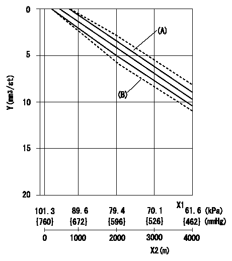
ACS adjustment
Full load injection quantity at high altitudes and ACS adjusting method
1. Full load injection quantity adjustment
(1)Remove the ACS cover and remove the bellows and adjusting shim.
(2)Perform all adjustments as per the adjustment standard except for ACS adjustment.
2. ACS adjustment
Adjust the ACS so that the reduction amount corresponds to the altitude in the table.
X1 = atmospheric pressure
X2 = altitude
Y = decrease quantity
(A) = adjustment value
(B) = test value
----------
N1=1250r/min
----------
----------
N1=1250r/min
----------
Information:
1. Overview of Lubrication System
Flow of oil2. Oil Pump, Relief Valve, and Oil Pressure Switch
2.1 Disassembly
Disassembly sequence and points to check on oil pump1 Oil filter2 Oil pump3 Gasket4 Oil pump cover5 Inner rotor6 Outer rotor (The inner and outer rotors form a rotor assembly)7 O-ring8 Oil pump body9 Relief valve10 Oil pressure switch KEY POINTS FOR DISASSEMBLY(1) Oil PumpRemove the oil pump (parts (3) through (8) in the above drawing) as an assembly.
Removing oil pump(2) Oil Pressure SwitchRemove the switch using the Oil Pressure Switch Socket Wrench (MD998054).
Removing oil pressure switch2.2 Inspection and Repair(1) Oil Pump(a) Using a thickness gauge, measure the clearance between the outer rotor and pump body. If the measurement exceeds the limit, replace the rotor assembly.
Unit: mm (in.)
Measuring outer rotor-to-pump body clearance(b) Using a thickness gauge, measure the clearance between the outer rotor and inner rotor. If the measurement exceeds the limit, replace the rotor assembly.
Unit: mm (in.)
Measuring outer rotor-to-inner rotor clearance(c) Using a straight edge and a thickness gauge, measure the clearance between the rotors and pump cover. If the measurement exceeds the limit, replace either the rotors or the pump body.
Unit: mm (in.)
Measuring clearance between rotors and pump over(2) Oil Pressure Switch(a) Connect a tester (set to the ohm range) between the terminal and body of the oil pressure switch. There should be continuity. If there is no continuity, the switch is faulty and should be replaced.
Inspecting oil pressure switch(b) Insert a thin rod into the oil hole in the switch body. When the rod is then pushed in gently, there should be no continuity between the switch body and terminal. If there is continuity, the switch is faulty and should be replaced.(c) Apply an air pressure of 49 kPa {0.5 kgf/cm2} (7.2 psi) to the switch through the oil hole. If there is no continuity, the switch is normal. Simultaneously, check for air leakage. Any air leakage means that the diaphragm is broken and, therefore, the switch should be replaced.
Inspecting oil pressure switch2.3 Assembly
Points to note during reassembly of oil pump KEY POINTS FOR REASSEMBLY Oil Pressure Switch(a) Install the switch using the Oil Pressure Switch Socket Wrench (MD998054).(b) Before installation, apply sealant to the threads of the switch. (Use either Hermeseal H1 or Threebond 1104).
(a) Avoid applying sealant excessively to prevent it from reaching the end of the threads.(b) Never tighten the switch to a torque exceeding specification.
Installing oil pressure switch