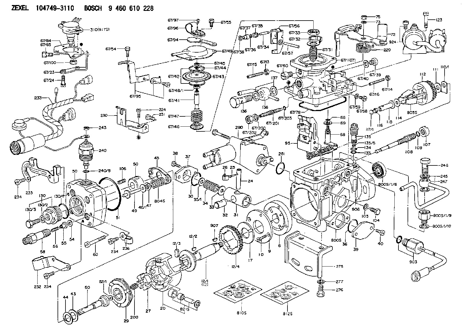
Information injection-pump assembly
BOSCH
9 460 610 228
9460610228
ZEXEL
104749-3110
1047493110
MITSUBISHI
MD104236
md104236

Rating:
Components :
| 0. | INJECTION-PUMP ASSEMBLY | 104749-3110 |
| 1. | _ | |
| 2. | FUEL INJECTION PUMP | 104649-3070 |
| 3. | NUMBER PLATE | 146900-0000 |
| 4. | _ | 479771-0520 |
| 5. | CAPSULE | |
| 6. | ADJUSTING DEVICE | |
| 7. | NOZZLE AND HOLDER ASSY | 105148-1112 |
| 8. | Nozzle and Holder | MD103301 |
| 9. | Open Pre:MPa(Kqf/cm2) | 11.8{120} |
| 10. | NOZZLE-HOLDER | 105078-0012 |
| 11. | NOZZLE | 105007-1120 |
Scheme ###:
| 1/6. | [1] | 146601-0700 | PACKING RING |
| 1/9. | [1] | 146616-5600 | ADAPTOR |
| 1/10. | [1] | 139512-0500 | GASKET |
| 6. | [1] | 146100-0120 | SUPPLY PUMP |
| 9. | [1] | 146103-0000 | COVER |
| 10. | [2] | 139104-0000 | FLAT-HEAD SCREW |
| 12. | [1] | 146200-0320 | DRIVE SHAFT |
| 12/1. | [1] | 146200-0300 | DRIVE SHAFT |
| 12/2. | [1] | 146201-0000 | WOODRUFF KEY |
| 12/3. | [2] | 146202-0100 | DAMPER |
| 12/4. | [1] | 146203-0000 | TOOTHED GEAR |
| 17. | [1] | 146204-0000 | PLAIN WASHER |
| 20. | [1] | 146210-0220 | ROLLER SET |
| 24. | [1] | 146303-0000 | BEARING PIN |
| 25. | [1] | 146304-0000 | BEARING PIN |
| 26. | [1] | 146305-0000 | CLAMPING BAND |
| 27. | [1] | 146205-0000 | SLOTTED WASHER |
| 29. | [1] | 146220-0020 | CAM PLATE |
| 30. | [1] | 146600-0800 | O-RING |
| 31. | [1] | 146300-0600 | PUMP PLUNGER |
| 32. | [1] | 146301-0000 | SLIDING PIECE |
| 33. | [1] | 146603-0700 | SHIM D17.5&7.5T0.60 |
| 34. | [1] | 146302-3400 | COMPRESSION SPRING |
| 34B. | [1] | 146302-3300 | COMPRESSION SPRING |
| 35/1. | [0] | 146603-0700 | SHIM D17.5&7.5T0.60 |
| 35/1. | [0] | 146603-0800 | SHIM D17.5&7.5T0.70 |
| 35/1. | [0] | 146603-0900 | SHIM D17.5&7.5T0.90 |
| 35/1. | [0] | 146603-1000 | SHIM D17.5&7.5T1.00 |
| 35/1. | [0] | 146603-1100 | SHIM D17.5&7.5T1.20 |
| 35/1. | [0] | 146603-3600 | SHIM D17.5&7.5T2.40 |
| 36. | [1] | 146600-0800 | O-RING |
| 37. | [1] | 146310-0000 | COVER |
| 38. | [2] | 146620-5000 | BLEEDER SCREW |
| 39. | [1] | 146310-0100 | COVER |
| 40. | [2] | 146620-5000 | BLEEDER SCREW |
| 43. | [1] | 146230-0000 | SHIM |
| 44. | [1] | 146230-0100 | PLAIN WASHER |
| 45. | [1] | 146231-0001 | SLOTTED WASHER |
| 47. | [2] | 146233-0000 | SLOTTED WASHER |
| 48/1. | [1] | 146603-0000 | SHIM D17.0&5.2T0.50 |
| 48/1. | [1] | 146603-0100 | SHIM D17.0&5.2T0.80 |
| 48/1. | [1] | 146603-0200 | SHIM D17.0&5.2T1.00 |
| 48/1. | [1] | 146603-0300 | SHIM D17.0&5.2T1.20 |
| 48/1. | [1] | 146603-0400 | SHIM D17.0&5.2T1.50 |
| 48/1. | [1] | 146603-0500 | SHIM D17.0&5.2T1.80 |
| 48/1. | [1] | 146603-0600 | SHIM D17.0&5.2T2.00 |
| 48/1. | [1] | 146690-1400 | SHIM D17&5.2T0.9 |
| 48/1. | [1] | 146690-1500 | SHIM D17&5.2T1.1 |
| 48/1. | [1] | 146690-1600 | SHIM D17&5.2T1.3 |
| 48/1. | [1] | 146690-1700 | SHIM D17&5.2T1.4 |
| 48/1. | [1] | 146690-1800 | SHIM D17&5.2T1.6 |
| 48/1. | [1] | 146690-1900 | SHIM D17&5.2T1.7 |
| 48/1. | [1] | 146690-5800 | SHIM |
| 48/1. | [1] | 146690-5900 | SHIM |
| 48/1. | [1] | 146690-6000 | SHIM |
| 48/1. | [1] | 146690-6100 | SHIM |
| 48/1. | [1] | 146690-6200 | SHIM |
| 48/1. | [1] | 146690-6300 | SHIM |
| 48/1. | [1] | 146690-6400 | SHIM |
| 48/1. | [1] | 146690-6500 | SHIM |
| 48/1. | [1] | 146690-6600 | SHIM |
| 48/1. | [1] | 146690-6700 | SHIM |
| 48/1. | [1] | 146690-6800 | SHIM |
| 48/1. | [1] | 146690-6900 | SHIM |
| 48/1. | [1] | 146690-7000 | SHIM |
| 48/1. | [1] | 146690-7100 | SHIM |
| 48/1. | [1] | 146690-7200 | SHIM |
| 48/1. | [1] | 146690-7300 | SHIM |
| 48/1. | [1] | 146690-7400 | SHIM |
| 48/1. | [1] | 146690-7500 | SHIM |
| 48/1. | [1] | 146690-7800 | SHIM |
| 49. | [2] | 146234-0500 | GUIDE PIN |
| 50. | [1] | 146400-7020 | HYDRAULIC HEAD |
| 50. | [1] | 146400-7020 | HYDRAULIC HEAD |
| 50. | [1] | 146400-7020 | HYDRAULIC HEAD |
| 51. | [1] | 146600-0000 | O-RING |
| 52/1. | [1] | 146420-0000 | SHIM D9.5&3.0T1.90 |
| 52/1. | [1] | 146420-0100 | SHIM D9.5&3.0T1.92 |
| 52/1. | [1] | 146420-0200 | SHIM D9.5&3.0T1.94 |
| 52/1. | [1] | 146420-0300 | SHIM D9.5&3.0T1.96 |
| 52/1. | [1] | 146420-0400 | SHIM D9.5&3.0T1.98 |
| 52/1. | [1] | 146420-0500 | SHIM D9.5&3.0T2.00 |
| 52/1. | [1] | 146420-0600 | SHIM D9.5&3.0T2.02 |
| 52/1. | [1] | 146420-0700 | SHIM D9.5&3.0T2.04 |
| 52/1. | [1] | 146420-0800 | SHIM D9.5&3.0T2.06 |
| 52/1. | [1] | 146420-0900 | SHIM D9.5&3.0T2.08 |
| 52/1. | [1] | 146420-1000 | SHIM D9.5&3.0T2.10 |
| 52/1. | [1] | 146420-1100 | SHIM D9.5&3.0T2.12 |
| 52/1. | [1] | 146420-1200 | SHIM D9.5&3.0T2.14 |
| 52/1. | [1] | 146420-1300 | SHIM D9.5&3.0T2.16 |
| 52/1. | [1] | 146420-1400 | SHIM D9.5&3.0T2.18 |
| 52/1. | [1] | 146420-1500 | SHIM D9.5&3.0T2.20 |
| 52/1. | [1] | 146420-1600 | SHIM D9.5&3.0T2.22 |
| 52/1. | [1] | 146420-1700 | SHIM D9.5&3.0T2.24 |
| 52/1. | [1] | 146420-1800 | SHIM D9.5&3.0T2.26 |
| 52/1. | [1] | 146420-1900 | SHIM D9.5&3.0T2.28 |
| 52/1. | [1] | 146420-2000 | SHIM D9.5&3.0T2.30 |
| 52/1. | [1] | 146420-2100 | SHIM D9.5&3.0T2.32 |
| 52/1. | [1] | 146420-2200 | SHIM D9.5&3.0T2.34 |
| 52/1. | [1] | 146420-2300 | SHIM D9.5&3.0T2.36 |
| 52/1. | [1] | 146420-2400 | SHIM D9.5&3.0T2.38 |
| 52/1. | [1] | 146420-2500 | SHIM D9.5&3.0T2.40 |
| 52/1. | [1] | 146420-2600 | SHIM D9.5&3.0T2.42 |
| 52/1. | [1] | 146420-2700 | SHIM D9.5&3.0T2.44 |
| 52/1. | [1] | 146420-2800 | SHIM D9.5&3.0T2.46 |
| 52/1. | [1] | 146420-2900 | SHIM D9.5&3.0T2.48 |
| 52/1. | [1] | 146420-3000 | SHIM D9.5&3.0T2.50 |
| 52/1. | [1] | 146420-3100 | SHIM D9.5&3.0T2.52 |
| 52/1. | [1] | 146420-3200 | SHIM D9.5&3.0T2.54 |
| 52/1. | [1] | 146420-3300 | SHIM D9.5&3.0T2.56 |
| 52/1. | [1] | 146420-3400 | SHIM D9.5&3.0T2.58 |
| 52/1. | [1] | 146420-3500 | SHIM D9.5&3.0T2.60 |
| 52/1. | [1] | 146420-3600 | SHIM D9.5&3.0T2.62 |
| 52/1. | [1] | 146420-3700 | SHIM D9.5&3.0T2.64 |
| 52/1. | [1] | 146420-3800 | SHIM D9.5&3.0T2.66 |
| 52/1. | [1] | 146420-3900 | SHIM D9.5&3.0T2.68 |
| 52/1. | [1] | 146420-4000 | SHIM D9.5&3.0T2.70 |
| 52/1. | [1] | 146420-4100 | SHIM D9.5&3.0T2.72 |
| 52/1. | [1] | 146420-4200 | SHIM D9.5&3.0T2.74 |
| 52/1. | [1] | 146420-4300 | SHIM D9.5&3.0T2.76 |
| 52/1. | [1] | 146420-4400 | SHIM D9.5&3.0T2.78 |
| 52/1. | [1] | 146420-4500 | SHIM D9.5&3.0T2.80 |
| 52/1. | [1] | 146420-4600 | SHIM D9.5&3.0T2.82 |
| 52/1. | [1] | 146420-4700 | SHIM D9.5&3.0T2.84 |
| 52/1. | [1] | 146420-4800 | SHIM D9.5&3.0T2.86 |
| 52/1. | [1] | 146420-4900 | SHIM D9.5&3.0T2.88 |
| 52/1. | [1] | 146420-5000 | SHIM D9.5&3.0T2.90 |
| 52/1. | [1] | 146420-5100 | SHIM D9.5&3.0T1.74 |
| 52/1. | [1] | 146420-5200 | SHIM D9.5&3.0T1.76 |
| 52/1. | [1] | 146420-5300 | SHIM D9.5&3.0T1.78 |
| 52/1. | [1] | 146420-5400 | SHIM D9.5&3.0T1.80 |
| 52/1. | [1] | 146420-5500 | SHIM D9.5&3.0T1.82 |
| 52/1. | [1] | 146420-5600 | SHIM D9.5&3.0T1.84 |
| 52/1. | [1] | 146420-5700 | SHIM D9.5&3.0T1.86 |
| 52/1. | [1] | 146420-5800 | SHIM D9.5&3.0T1.88 |
| 54. | [4] | 146433-0100 | GASKET D12&6.4T1.00 |
| 55. | [4] | 146430-0320 | DELIVERY-VALVE ASSEMBLY |
| 56. | [4] | 146432-0000 | COMPRESSION SPRING |
| 58. | [4] | 146440-0320 | FITTING |
| 60. | [4] | 139106-0100 | FLAT-HEAD SCREW |
| 66. | [1] | 146600-0100 | O-RING |
| 67. | [1] | 146700-2820 | MANIFOLD-PRESSURE COMP. |
| 67/1. | [1] | 146508-5520 | GOVERNOR COVER |
| 67/13. | [1] | 146621-1700 | UNION NUT |
| 67/14. | [1] | 146621-1800 | UNION NUT |
| 67/15. | [1] | 146526-3000 | BLEEDER SCREW |
| 67/16. | [1] | 146526-3500 | BLEEDER SCREW |
| 67/23. | [1] | 146628-0100 | PLATE |
| 67/24. | [2] | 139106-0500 | FLAT-HEAD SCREW M6P1.0H25 |
| 67/31. | [1] | 146710-0800 | BUSHING |
| 67/32. | [1] | 146711-0000 | PLATE |
| 67/33. | [1] | 139218-0400 | UNION NUT |
| 67/34. | [1] | 146712-0700 | BEARING PIN |
| 67/35. | [1] | 146621-0300 | UNION NUT |
| 67/36. | [1] | 146600-1400 | O-RING |
| 67/37. | [1] | 146710-0100 | BUSHING |
| 67/38. | [1] | 139506-0200 | GASKET D8.9&6.8T1.00 |
| 67/39. | [1] | 146620-0300 | CAPSULE |
| 67/40. | [1] | 026512-1540 | GASKET D15.4&12.2T1.50 |
| 67/41. | [1] | 146713-4100 | ADJUSTING PIN |
| 67/42. | [2] | 146714-0000 | PLATE |
| 67/43. | [1] | 146715-0000 | DIAPHRAGM |
| 67/44. | [1] | 139306-0100 | LOCKING WASHER |
| 67/45. | [1] | 013030-6040 | UNION NUT M6P1H3.6 |
| 67/46. | [1] | 146716-0000 | UNION NUT |
| 67/47. | [1] | 146717-0400 | COILED SPRING |
| 67/48/1. | [1] | 146720-0000 | SPACER BUSHING L3.7 |
| 67/48/1. | [1] | 146720-0100 | SPACER BUSHING L3.9 |
| 67/48/1. | [1] | 146720-0200 | SPACER BUSHING L4.1 |
| 67/48/1. | [1] | 146720-0300 | SPACER BUSHING L4.3 |
| 67/48/1. | [1] | 146720-0400 | SPACER BUSHING L4.5 |
| 67/48/1. | [1] | 146720-0500 | SPACER BUSHING L4.7 |
| 67/48/1. | [1] | 146720-0600 | SPACER BUSHING L4.9 |
| 67/48/1. | [1] | 146720-0700 | SPACER BUSHING L5.1 |
| 67/48/1. | [1] | 146720-0800 | SPACER BUSHING L5.3 |
| 67/48/1. | [1] | 146720-0900 | SPACER BUSHING L2.7 |
| 67/48/1. | [1] | 146720-1000 | SPACER BUSHING L2.9 |
| 67/48/1. | [1] | 146720-1100 | SPACER BUSHING L3.1 |
| 67/48/1. | [1] | 146720-1200 | SPACER BUSHING L3.3 |
| 67/48/1. | [1] | 146720-1300 | SPACER BUSHING L3.5 |
| 67/48/1. | [1] | 146720-1400 | SPACER BUSHING L2.8 |
| 67/48/1. | [1] | 146720-1500 | SPACER BUSHING L3.0 |
| 67/48/1. | [1] | 146720-1600 | SPACER BUSHING L3.2 |
| 67/48/1. | [1] | 146720-1700 | SPACER BUSHING L3.4 |
| 67/48/1. | [1] | 146720-1800 | SPACER BUSHING L3.6 |
| 67/48/1. | [1] | 146720-1900 | SPACER BUSHING L3.8 |
| 67/48/1. | [1] | 146720-2000 | SPACER BUSHING L4.0 |
| 67/48/1. | [1] | 146720-2100 | SPACER BUSHING L4.2 |
| 67/48/1. | [1] | 146720-2200 | SPACER BUSHING L4.4 |
| 67/48/1. | [1] | 146720-2300 | SPACER BUSHING L4.6 |
| 67/48/1. | [1] | 146720-2400 | SPACER BUSHING L4.8 |
| 67/48/1. | [1] | 146720-2500 | SPACER BUSHING L5.0 |
| 67/48/1. | [1] | 146720-2600 | SPACER BUSHING L5.2 |
| 67/48/1. | [1] | 146720-2700 | SPACER BUSHING L5.4 |
| 67/48/1. | [1] | 146720-2800 | SPACER BUSHING L5.5 |
| 67/48/1. | [1] | 146720-2900 | SPACER BUSHING L5.6 |
| 67/48/1. | [1] | 146720-4500 | SPACER BUSHING L1.8 |
| 67/48/1. | [1] | 146720-4600 | SPACER BUSHING L1.9 |
| 67/48/1. | [1] | 146720-4700 | SPACER BUSHING L2.0 |
| 67/48/1. | [1] | 146720-4800 | SPACER BUSHING L2.1 |
| 67/48/1. | [1] | 146720-4900 | SPACER BUSHING L2.2 |
| 67/48/1. | [1] | 146720-5000 | SPACER BUSHING L2.3 |
| 67/48/1. | [1] | 146720-5100 | SPACER BUSHING L2.4 |
| 67/48/1. | [1] | 146720-5200 | SPACER BUSHING L2.5 |
| 67/48/1. | [1] | 146720-5300 | SPACER BUSHING L2.6 |
| 67/48/1. | [1] | 146725-2500 | SPACER BUSHING L5.7 |
| 67/48/1. | [1] | 146725-2600 | SPACER BUSHING L5.8 |
| 67/48/1. | [1] | 146725-2700 | SPACER BUSHING L5.9 |
| 67/48/1. | [1] | 146725-2800 | SPACER BUSHING L6.0 |
| 67/48/1. | [1] | 146725-2900 | SPACER BUSHING L6.1 |
| 67/48/1. | [1] | 146725-3000 | SPACER BUSHING L6.2 |
| 67/48/1. | [1] | 146725-3100 | SPACER BUSHING L6.3 |
| 67/48/1. | [1] | 146725-3200 | SPACER BUSHING L6.4 |
| 67/48/1. | [1] | 146725-3300 | SPACER BUSHING L6.5 |
| 67/48/1. | [1] | 146725-3400 | SPACER BUSHING L6.6 |
| 67/48/1. | [1] | 146725-3500 | SPACER BUSHING L6.7 |
| 67/48/1. | [1] | 146725-3600 | SPACER BUSHING L6.8 |
| 67/48/1. | [1] | 146725-3700 | SPACER BUSHING L6.9 |
| 67/48/1. | [1] | 146725-3800 | SPACER BUSHING L7.0 |
| 67/48/1. | [1] | 146725-3900 | SPACER BUSHING L7.1 |
| 67/48/1. | [1] | 146725-4000 | SPACER BUSHING L7.2 |
| 67/48/1. | [1] | 146725-4100 | SPACER BUSHING L7.3 |
| 67/48/1. | [1] | 146725-4200 | SPACER BUSHING L7.4 |
| 67/48/1. | [1] | 146725-4300 | SPACER BUSHING L7.5 |
| 67/49. | [1] | 146721-1320 | COVER |
| 67/54. | [2] | 020006-1440 | BLEEDER SCREW M6P1L14 |
| 67/55. | [2] | 020006-2040 | BLEEDER SCREW M6P1L20 4T |
| 67/56. | [1] | 146723-0020 | CONTROL LEVER |
| 67/57. | [1] | 146712-0100 | BEARING PIN |
| 67/58. | [2] | 146620-0600 | CAPSULE |
| 67/59. | [2] | 026506-1040 | GASKET D9.9&6.2T1 |
| 67/60. | [1] | 146724-0020 | AIR FILTER |
| 67/64. | [1] | 146625-6800 | BRACKET |
| 67/65. | [1] | 020106-1040 | BLEEDER SCREW M6P1L12 |
| 67/78. | [1] | 146600-4400 | SEAL RING |
| 67/94. | [1] | 146628-2700 | BRACKET |
| 67/95. | [1] | 146626-4120 | BRACKET |
| 67/96. | [1] | 146659-4800 | CLAMPING BAND |
| 67/97. | [1] | 012154-1040 | FLAT-HEAD SCREW M4P0.7L10 |
| 67/100. | [1] | 013020-6040 | UNION NUT M6P1H5 |
| 67/200. | [1] | 139308-0300 | PLAIN WASHER |
| 67/201. | [1] | 146545-0300 | THREADED PIN L53.00 |
| 67/201B. | [1] | 146545-0400 | THREADED PIN L55.00 |
| 67/201C. | [1] | 146545-0500 | THREADED PIN L57.00 |
| 67/202. | [1] | 139208-0100 | UNION NUT |
| 67/203. | [1] | 146600-1200 | O-RING |
| 68. | [1] | 146510-5120 | CONTROL SHAFT |
| 69. | [1] | 139310-0200 | PLAIN WASHER |
| 72. | [1] | 146534-9320 | CONTROL LEVER |
| 72B. | [1] | 146534-9420 | CONTROL LEVER |
| 73. | [1] | 014110-6440 | LOCKING WASHER |
| 75. | [1] | 146621-0700 | UNION NUT |
| 95. | [1] | 146550-0520 | FULCRUM LEVER |
| 104. | [2] | 146568-0000 | SLOTTED SPRING PIN |
| 105. | [2] | 026508-1140 | GASKET D11.4&8.2T1 |
| 106. | [2] | 146588-0500 | COILED SPRING |
| 107. | [1] | 146569-0300 | UNION NUT |
| 108. | [1] | 146570-0420 | GOVERNOR SHAFT |
| 109. | [1] | 146600-0400 | O-RING |
| 110/1. | [1] | 146571-0000 | SHIM D20.2&8.3T1.05 |
| 110/1. | [1] | 146571-0100 | SHIM D20.2&8.3T1.25 |
| 110/1. | [1] | 146571-0200 | SHIM D20.2&8.3T1.45 |
| 110/1. | [1] | 146571-0300 | SHIM D20.2&8.3T1.65 |
| 110/1. | [1] | 146571-0400 | SHIM D20.2&8.3T1.85 |
| 110/1. | [1] | 146571-0500 | SHIM D20.2&8.3T1.15 |
| 110/1. | [1] | 146571-0600 | SHIM D20.2&8.3T1.35 |
| 110/1. | [1] | 146571-0700 | SHIM D20.2&8.3T1.55 |
| 110/1. | [1] | 146571-0800 | SHIM D20.2&8.3T1.75 |
| 111. | [1] | 146602-0600 | PLAIN WASHER D20&8.4T1.40 |
| 112. | [1] | 146572-0020 | FLYWEIGHT ASSEMBLY |
| 114. | [1] | 146602-0500 | PLAIN WASHER D17&6.4T1.60 |
| 115. | [1] | 146575-3500 | SLIDING SLEEVE |
| 116. | [1] | 146576-0200 | CAP |
| 117/1. | [1] | 146577-1800 | PLUG L2.10 |
| 117/1. | [1] | 146577-1900 | PLUG L2.30 |
| 117/1. | [1] | 146577-2000 | PLUG L2.50 |
| 117/1. | [1] | 146577-2100 | PLUG L2.70 |
| 117/1. | [1] | 146577-2200 | PLUG L2.90 |
| 117/1. | [1] | 146577-2300 | PLUG L3.10 |
| 117/1. | [1] | 146577-2400 | PLUG L3.30 |
| 117/1. | [1] | 146577-2500 | PLUG L3.50 |
| 117/1. | [1] | 146577-2600 | PLUG L3.70 |
| 117/1. | [1] | 146577-2700 | PLUG L3.90 |
| 117/1. | [1] | 146577-2800 | PLUG L4.10 |
| 117/1. | [1] | 146577-2900 | PLUG L4.30 |
| 117/1. | [1] | 146577-3000 | PLUG L4.50 |
| 117/1. | [1] | 146577-3100 | PLUG L4.70 |
| 117/1. | [1] | 146577-3200 | PLUG L4.90 |
| 117/1. | [1] | 146577-3300 | PLUG L5.10 |
| 117/1. | [1] | 146577-6700 | PLUG L2.2 |
| 117/1. | [1] | 146577-6800 | PLUG L2.4 |
| 117/1. | [1] | 146577-6900 | PLUG L2.6 |
| 117/1. | [1] | 146577-7000 | PLUG L2.8 |
| 117/1. | [1] | 146577-7100 | PLUG L3.0 |
| 117/1. | [1] | 146577-7200 | PLUG L3.2 |
| 117/1. | [1] | 146577-7300 | PLUG L3.4 |
| 117/1. | [1] | 146577-7400 | PLUG L3.6 |
| 117/1. | [1] | 146577-7500 | PLUG L3.8 |
| 117/1. | [1] | 146577-7600 | PLUG L4.0 |
| 117/1. | [1] | 146577-7700 | PLUG L4.2 |
| 117/1. | [1] | 146577-7800 | PLUG L4.4 |
| 117/1. | [1] | 146577-7900 | PLUG L4.6 |
| 117/1. | [1] | 146577-8000 | PLUG L4.8 |
| 117/1. | [1] | 146577-8100 | PLUG L5.0 |
| 117/1. | [1] | 146877-0000 | PLUG L5.2 |
| 117/1. | [1] | 146877-0100 | PLUG L5.3 |
| 117/1. | [1] | 146877-0200 | PLUG L5.4 |
| 117/1. | [1] | 146877-0300 | PLUG L5.5 |
| 117/1. | [1] | 146877-4700 | PLUG |
| 117/1. | [1] | 146877-4800 | PLUG |
| 117/1. | [1] | 146877-4900 | PLUG |
| 117/1. | [1] | 146877-5000 | PLUG |
| 123. | [4] | 146620-0500 | HEX-SOCKET-HEAD CAP SCREW |
| 130. | [1] | 146421-0020 | CAPSULE |
| 130/2. | [1] | 026508-1140 | GASKET D11.4&8.2T1 |
| 130/3. | [1] | 146422-0000 | BLEEDER SCREW |
| 130/4. | [1] | 146600-0500 | O-RING |
| 133. | [1] | 146600-0600 | O-RING |
| 134. | [1] | 146600-0700 | O-RING |
| 135. | [1] | 146110-0220 | CONTROL VALVE |
| 135/5. | [1] | 146114-0000 | SPRING WASHER |
| 136. | [1] | 146120-0020 | OVER FLOW VALVE |
| 137. | [2] | 139512-0500 | GASKET |
| 138. | [1] | 146607-0520 | INLET UNION |
| 200. | [1] | 146206-0100 | COILED SPRING |
| 220. | [1] | 146587-1500 | COILED SPRING |
| 224. | [1] | 139106-0400 | FLAT-HEAD SCREW M6P1.0H12 |
| 230. | [1] | 146626-2400 | BRACKET |
| 231. | [1] | 139106-0400 | FLAT-HEAD SCREW M6P1.0H12 |
| 232. | [1] | 146659-2320 | CLAMPING BAND |
| 233. | [1] | 146658-9020 | WIRE |
| 234. | [3] | 139106-0500 | FLAT-HEAD SCREW M6P1.0H25 |
| 234. | [3] | 139106-0500 | FLAT-HEAD SCREW M6P1.0H25 |
| 234. | [3] | 139106-0500 | FLAT-HEAD SCREW M6P1.0H25 |
| 235. | [1] | 146659-2400 | CLAMPING BAND |
| 236. | [1] | 146659-1420 | CLAMPING BAND |
| 240. | [1] | 146650-1220 | PULLING ELECTROMAGNET |
| 240/8. | [1] | 146600-1700 | O-RING |
| 243. | [1] | 146621-1000 | UNION NUT |
| 245. | [2] | 139512-0500 | GASKET |
| 246. | [1] | 027412-2440 | EYE BOLT |
| 247. | [1] | 146606-3320 | INLET UNION |
| 275. | [1] | 146626-2500 | BRACKET |
| 276. | [2] | 010010-1640 | BLEEDER SCREW M10P1.5L16 4T |
| 277. | [2] | 014111-0440 | LOCKING WASHER |
| 280. | [1] | 146360-3220 | START ADVANCE ASSY |
| 281. | [1] | 146600-0800 | O-RING |
| 310. | [1] | 146673-3321 | POTENTCIOMETER |
| 800S. | [1] | 146009-6220 | PUMP HOUSING |
| 800S/1/6. | [1] | 146601-0700 | PACKING RING |
| 800S/1/9. | [1] | 146616-5600 | ADAPTOR |
| 800S/1/10. | [1] | 139512-0500 | GASKET |
| 804S. | [1] | 146232-0320 | COMPRESSION SPRING |
| 805S. | [1] | 146574-0120 | PARTS SET |
| 810S. | [1] | 146600-1120 | REPAIR SET |
| 812S. | [1] | 146600-1920 | PARTS SET |
| 821S. | [1] | 146210-5720 | ROLLER SET |
| 903. | [1] | 479771-0520 | PULSE GENERATOR |
| 906. | [1] | 146900-0000 | NAMEPLATE |
| 907. | [1] | 029470-4030 | WOODRUFF KEY |
| 917S. | [1] | 146684-0610 | POTENTCIOMETER |
| 924. | [1] | 146680-2020 | DAMPER |
Include in #2:
104749-3110
as INJECTION-PUMP ASSEMBLY
Cross reference number
BOSCH
9 460 610 228
9460610228
ZEXEL
104749-3110
1047493110
MITSUBISHI
MD104236
md104236
Zexel num
Bosch num
Firm num
Name
104749-3110
9 460 610 228
MD104236 MITSUBISHI
INJECTION-PUMP ASSEMBLY
4D65 K
4D65 K
Calibration Data:
Adjustment conditions
Test oil
1404 Test oil ISO4113orSAEJ967d
1404 Test oil ISO4113orSAEJ967d
Test oil temperature
degC
45
45
50
Nozzle
105000-2010
Bosch type code
NP-DN12SD12TT
Nozzle holder
105780-2080
Opening pressure
MPa
14.7
14.7
15.19
Opening pressure
kgf/cm2
150
150
155
Injection pipe
Inside diameter - outside diameter - length (mm) mm 2-6-840
Inside diameter - outside diameter - length (mm) mm 2-6-840
Transfer pump pressure
kPa
20
20
20
Transfer pump pressure
kgf/cm2
0.2
0.2
0.2
Direction of rotation (viewed from drive side)
Right R
Right R
Injection timing adjustment
Pump speed
r/min
1250
1250
1250
Boost pressure
kPa
78.65
77.3
80
Boost pressure
mmHg
590
580
600
Average injection quantity
mm3/st.
46.8
46.3
47.3
Difference in delivery
mm3/st.
3.5
Basic
*
Remarks
Refer to additional devices.
Refer to additional devices.
Injection timing adjustment_02
Pump speed
r/min
750
750
750
Boost pressure
kPa
33.35
32
34.7
Boost pressure
mmHg
250
240
260
Average injection quantity
mm3/st.
40.7
40.2
41.2
Difference in delivery
mm3/st.
3
Basic
*
Remarks
Refer to additional devices.
Refer to additional devices.
Injection timing adjustment_03
Pump speed
r/min
2750
2750
2750
Boost pressure
kPa
0
0
0
Boost pressure
mmHg
0
0
0
Average injection quantity
mm3/st.
6.5
1.5
11.5
Injection timing adjustment_04
Pump speed
r/min
2250
2250
2250
Boost pressure
kPa
78.65
77.3
80
Boost pressure
mmHg
590
580
600
Average injection quantity
mm3/st.
40.7
38.2
43.2
Injection timing adjustment_05
Pump speed
r/min
1250
1250
1250
Boost pressure
kPa
78.65
77.3
80
Boost pressure
mmHg
590
580
600
Average injection quantity
mm3/st.
46.8
45.8
47.8
Injection timing adjustment_06
Pump speed
r/min
750
750
750
Boost pressure
kPa
33.35
32
34.7
Boost pressure
mmHg
250
240
260
Average injection quantity
mm3/st.
40.7
39.7
41.7
Injection timing adjustment_07
Pump speed
r/min
600
600
600
Boost pressure
kPa
0
0
0
Boost pressure
mmHg
0
0
0
Average injection quantity
mm3/st.
35.2
32.7
37.7
Injection quantity adjustment
Pump speed
r/min
2750
2750
2750
Boost pressure
kPa
0
0
0
Boost pressure
mmHg
0
0
0
Average injection quantity
mm3/st.
6.5
3.5
9.5
Basic
*
Injection quantity adjustment_02
Pump speed
r/min
3000
3000
3000
Boost pressure
kPa
0
0
0
Boost pressure
mmHg
0
0
0
Average injection quantity
mm3/st.
3
Governor adjustment
Pump speed
r/min
400
400
400
Boost pressure
kPa
0
0
0
Boost pressure
mmHg
0
0
0
Average injection quantity
mm3/st.
6.5
5
8
Difference in delivery
mm3/st.
2
Basic
*
Governor adjustment_02
Pump speed
r/min
600
600
600
Boost pressure
kPa
0
0
0
Boost pressure
mmHg
0
0
0
Average injection quantity
mm3/st.
2
Governor adjustment_03
Pump speed
r/min
400
400
400
Boost pressure
kPa
0
0
0
Boost pressure
mmHg
0
0
0
Average injection quantity
mm3/st.
6.5
4.5
8.5
Timer adjustment
Pump speed
r/min
100
100
100
Boost pressure
kPa
0
0
0
Boost pressure
mmHg
0
0
0
Average injection quantity
mm3/st.
53
43
63
Basic
*
Speed control lever angle
Pump speed
r/min
400
400
400
Boost pressure
kPa
0
0
0
Boost pressure
mmHg
0
0
0
Average injection quantity
mm3/st.
0
0
0
Remarks
Magnet OFF
Magnet OFF
0000000901
Pump speed
r/min
1250
1250
1250
Boost pressure
kPa
0
0
0
Boost pressure
mmHg
0
0
0
Overflow quantity
cm3/min
420
288
552
Stop lever angle
Pump speed
r/min
1250
1250
1250
Boost pressure
kPa
78.65
77.3
80
Boost pressure
mmHg
590
580
600
Pressure
kPa
470.5
441
500
Pressure
kgf/cm2
4.8
4.5
5.1
Basic
*
Stop lever angle_02
Pump speed
r/min
600
600
600
Boost pressure
kPa
78.65
77.3
80
Boost pressure
mmHg
590
580
600
Pressure
kPa
313.5
284
343
Pressure
kgf/cm2
3.2
2.9
3.5
Stop lever angle_03
Pump speed
r/min
1250
1250
1250
Boost pressure
kPa
78.65
77.3
80
Boost pressure
mmHg
590
580
600
Pressure
kPa
470.5
441
500
Pressure
kgf/cm2
4.8
4.5
5.1
Stop lever angle_04
Pump speed
r/min
2250
2250
2250
Boost pressure
kPa
78.65
77.3
80
Boost pressure
mmHg
590
580
600
Pressure
kPa
696.5
667
726
Pressure
kgf/cm2
7.1
6.8
7.4
0000001101
Pump speed
r/min
1250
1250
1250
Boost pressure
kPa
78.65
77.3
80
Boost pressure
mmHg
590
580
600
Timer stroke
mm
4.1
3.9
4.3
Basic
*
_02
Pump speed
r/min
600
600
600
Boost pressure
kPa
78.65
77.3
80
Boost pressure
mmHg
590
580
600
Timer stroke
mm
1.3
0.7
1.9
_03
Pump speed
r/min
1250
1250
1250
Boost pressure
kPa
78.65
77.3
80
Boost pressure
mmHg
590
580
600
Timer stroke
mm
4.1
3.7
4.5
_04
Pump speed
r/min
2250
2250
2250
Boost pressure
kPa
78.65
77.3
80
Boost pressure
mmHg
590
580
600
Timer stroke
mm
8.2
7.8
8.6
0000001201
Max. applied voltage
V
8
8
8
Test voltage
V
13
12
14
0000001401
Pump speed
r/min
1250
1250
1250
Boost pressure
kPa
0
0
0
Boost pressure
mmHg
0
0
0
Average injection quantity
mm3/st.
33.2
32.2
34.2
Timer stroke variation dT
mm
0.6
0.4
0.8
Basic
*
_02
Pump speed
r/min
1250
1250
1250
Boost pressure
kPa
0
0
0
Boost pressure
mmHg
0
0
0
Average injection quantity
mm3/st.
33.2
32.2
34.2
Timer stroke TA
mm
3.5
3.5
3.5
Timer stroke variation dT
mm
0.6
0.2
1
_03
Pump speed
r/min
1250
1250
1250
Boost pressure
kPa
0
0
0
Boost pressure
mmHg
0
0
0
Average injection quantity
mm3/st.
25.2
24.2
26.2
Timer stroke TA
mm
2.9
2.3
3.5
Timer stroke variation dT
mm
1.2
1.2
1.2
Timing setting
K dimension
mm
3.3
3.2
3.4
KF dimension
mm
5.8
5.7
5.9
MS dimension
mm
1
0.9
1.1
BCS stroke
mm
3.6
3.5
3.7
Control lever angle alpha
deg.
59
55
63
Control lever angle beta
deg.
41
38
44
Test data Ex:
0000001801 DASHPOT ADJUSTMENT
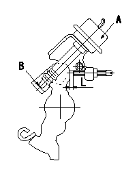
Adjustment of the dash pot
Adjust the lever position so that the lever and the dashpot contact at a deg (L mm) from the idle lever position.
A = dashpot
b = dashpot contact point
----------
a=8+-2deg L=5.2+-1mm
----------
L=5.2mm
----------
a=8+-2deg L=5.2+-1mm
----------
L=5.2mm
0000001901 BOOST COMPENSATOR ADJUSTMENT
BCS adjustment procedure
1. At pump speed N1 and boost pressure P1 confirm that the BCS moves through its full stroke and then adjust the injection quantity.
2. At pump speed N2 and boost pressure P2, adjust the full load injection quantity using the BCS spring set screw.
----------
N1=1250r/min N2=750r/min P1=78.6kPa(590mmHg) P2=33.3kPa(250mmHg)
----------
----------
N1=1250r/min N2=750r/min P1=78.6kPa(590mmHg) P2=33.3kPa(250mmHg)
----------
0000002001 W-CSD ADJUSTMENT
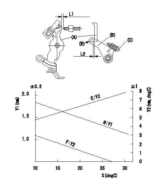
Adjustment of the W-CSD
Adjust for the ambient temperature at adjustment in accordance with the graph.
(1)Timer stroke: adjust according to graph.
(2)Fast idle (D): insert a block gauge L1 between the control lever (A) and the idle adjusting screw.
Adjust screw (C) so that clearance between the control lever (A) and the fast idle lever's pin (B) is L2 as determined from the graph.
Y1 = timer stroke
Y2 = control lever position
X = temperature
Y1 = timer stroke
Y2 = lever position
E = lever position (mm)
F = lever angle (deg)
G = timer stroke (mm)
----------
L1=5.3+-0.05mm
----------
L=5.3mm E=Y2=0.152X+3.25(mm) F=Y2=-(mm) G=Y1=-0.035X+2.2(mm)
----------
L1=5.3+-0.05mm
----------
L=5.3mm E=Y2=0.152X+3.25(mm) F=Y2=-(mm) G=Y1=-0.035X+2.2(mm)
0000002101 POTENTIOMETER ADJUSTMENT
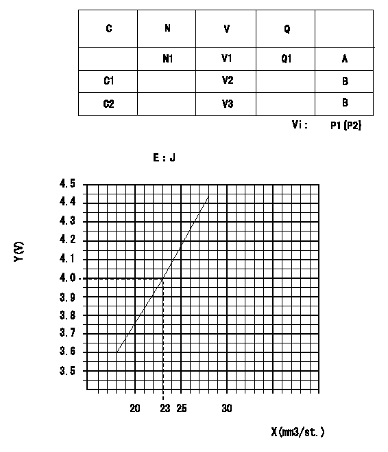
Adjustment of the potentiometer
In the following condition, change the installation position of the potentiometer to adjust the output voltage to within the specified values.
At N (pump speed) = N1 r/min and control lever position a (corresponding to shim thickness L mm), measure the injection quantity, calculate the voltage using the formula and adjust the potentiometer.
Vi:Applied voltage
C:Position of the control lever
N:Pump speed (r/min)
V:Output voltage (V)
Q:Injection quantity (mm3/st)
A:Adjusting point
B:Checking point
C1:Idle
C2:Full speed
P1:Boost pressure
P2:Boost pressure
E:Conversion formula
X:Injection quantity Q (cm3/1,000st)
Y:Voltage (V)
----------
N1=1000r/min a=19deg L=12.1mm
----------
N1=1000r/min V1=4+-0.03V V2=0.8+-0.7V V3=7.7+-1.2V Q1=22.9cm3/1,000st Vi=10V P1=-kPa P2=-mmHg J=V+-0.03=0.0856Q+2.04
----------
N1=1000r/min a=19deg L=12.1mm
----------
N1=1000r/min V1=4+-0.03V V2=0.8+-0.7V V3=7.7+-1.2V Q1=22.9cm3/1,000st Vi=10V P1=-kPa P2=-mmHg J=V+-0.03=0.0856Q+2.04
Information:
Changing Filter Element
A 1U-9578 Repair Kit (Nozzle Tester) is available to maintain the tester. The repair kit contains a new filter along with seals, gaskets, and instructions on how to use the kit. Do not reuse seals and gaskets when changing the filter. Always use new seals and gaskets.Calibration Fluid
The calibration fluid should be changed every three months or after testing 50 nozzles. The fluid should also be changed whenever inaccurate test results are suspected.Inaccurate test results can be caused by fluid with improper specific gravity, viscosity, visible contamination, fluid that foams, or discolored fluid.The fluid should also be checked for the correct viscosity. It is a good practice to test new calibration fluid for the correct viscosity and specific gravity. Use a 9U-7840 Test Kit to check calibration fluid.
Do not refill the nozzle tester with test oil that has been pumped through a fuel injection nozzle. Nozzles contain residual amounts of diesel fuel that is pumped out when tested. The diesel fuel mixes with and contaminates the test oil. Using this diesel fuel test oil combination will damage the nozzle tester.
9U-7840 Test Kit For Checking Fluid Viscosity Calibration fluid will last longer if the nozzles are cleaned prior to testing. As the fluid in the tester becomes contaminated, the accuracy of the test results are decreased.Changing Calibration Fluid
1. Completely drain the reservoir and any fluid contained in the pump mechanism. Special care must be taken for the disposal of the calibration fluid. Recent regulations prohibit the dumping of oil; all oil must be properly disposed.2. Thoroughly clean the reservoir using an 8T-9011 Component Cleaner or equivalent and clean towels.3. Install a new 8T-5313 Filter Element (10 micron). A new filter element should be installed whenever the calibration fluid is changed (even if less than 3 months).4. Fill the reservoir with clean calibration fluid (refer to the chart for part numbers).Nozzle Tester Pressure Gauges
Pressure gauges in the nozzle tester should be checked for accuracy every 12 months or whenever inaccurate test results are suspected. Gauges should also be checked whenever a gauge is damaged or the needle does not return to zero. Record all data on the data sheets in the "Forms" section.1. Remove pressure gauge from the nozzle tester.2. Install gauge adapter from 5P-8558 Calibrating Group Pressure Gauge onto pressure gauge.3. Connect pressure to tester port.4. Use a 1U-5230 Hand Pump to apply pressure to the gauge. Increase the pressure to 25% of the pressure gauges capacity.5. Check the actual gauge pressure with the tester gauge reading. The two pressures should be within two percent of each other.6. Repeat Step 5 at 50, 75 and 100 percent increments. Each increment should be within two percent of the tester gauge reading.7. If the pressure is not within two percent, the pressure gauge should be replaced.Check Tester For Leakage
Before testing any nozzle, check the tester for obvious external leakage. Leakage in the tester will give inaccurate test results, causing good nozzles to be rejected.Always check the tester for leakage
Have questions with 104749-3110?
Group cross 104749-3110 ZEXEL
Mitsubishi
104749-3110
9 460 610 228
MD104236
INJECTION-PUMP ASSEMBLY
4D65
4D65