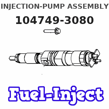
Information injection-pump assembly
BOSCH
9 460 610 247
9460610247
ZEXEL
104749-3080
1047493080
MITSUBISHI
MD113131
md113131
Rating:
Components :
| 0. | INJECTION-PUMP ASSEMBLY | 104749-3080 |
| 1. | _ | |
| 2. | FUEL INJECTION PUMP | 104649-3050 |
| 3. | NUMBER PLATE | |
| 4. | _ | |
| 5. | CAPSULE | |
| 6. | ADJUSTING DEVICE | |
| 7. | NOZZLE AND HOLDER ASSY | 105148-1012 |
| 8. | Nozzle and Holder | |
| 9. | Open Pre:MPa(Kqf/cm2) | 11.8(120) |
| 10. | NOZZLE-HOLDER | 105078-0012 |
| 11. | NOZZLE | 105007-1000 |
Scheme ###:
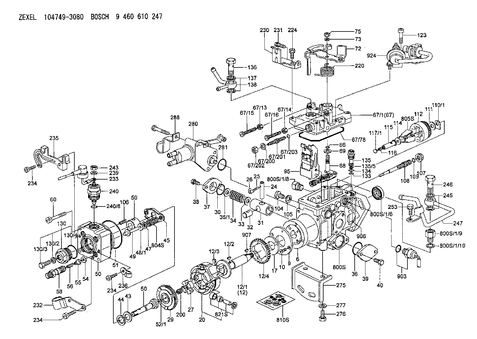
| 1/6. | [1] | 146601-0700 | PACKING RING |
| 1/9. | [1] | 146616-5600 | ADAPTOR |
| 1/10. | [1] | 139512-0500 | GASKET |
| 6. | [1] | 146100-0120 | SUPPLY PUMP |
| 9. | [1] | 146103-0000 | COVER |
| 10. | [2] | 139104-0000 | FLAT-HEAD SCREW |
| 12. | [1] | 146200-0320 | DRIVE SHAFT |
| 12/1. | [1] | 146200-0300 | DRIVE SHAFT |
| 12/2. | [1] | 146201-0000 | WOODRUFF KEY |
| 12/3. | [2] | 146202-0100 | DAMPER |
| 12/4. | [1] | 146203-0000 | TOOTHED GEAR |
| 17. | [1] | 146204-0000 | PLAIN WASHER |
| 20. | [1] | 146210-0220 | ROLLER SET |
| 24. | [1] | 146303-0000 | BEARING PIN |
| 25. | [1] | 146304-0000 | BEARING PIN |
| 26. | [1] | 146305-0000 | CLAMPING BAND |
| 27. | [1] | 146205-0000 | SLOTTED WASHER |
| 29. | [1] | 146220-0020 | CAM PLATE |
| 30. | [1] | 146600-0800 | O-RING |
| 31. | [1] | 146300-2200 | PUMP PLUNGER |
| 32. | [1] | 146301-0000 | SLIDING PIECE |
| 33. | [1] | 146603-0700 | SHIM |
| 34. | [1] | 146302-3400 | COMPRESSION SPRING |
| 35/1. | [0] | 146603-0700 | SHIM D17.5&7.5T0.60 |
| 35/1. | [0] | 146603-0800 | SHIM D17.5&7.5T0.70 |
| 35/1. | [0] | 146603-0900 | SHIM D17.5&7.5T0.90 |
| 35/1. | [0] | 146603-1000 | SHIM D17.5&7.5T1.00 |
| 35/1. | [0] | 146603-1100 | SHIM D17.5&7.5T1.20 |
| 35/1. | [0] | 146603-3600 | SHIM D17.5&7.5T2.40 |
| 36. | [1] | 146600-0800 | O-RING |
| 37. | [1] | 146310-0000 | COVER |
| 38. | [2] | 146620-5000 | BLEEDER SCREW |
| 39. | [1] | 146310-0100 | COVER |
| 40. | [2] | 146620-5000 | BLEEDER SCREW |
| 43. | [1] | 146230-0000 | SHIM |
| 44. | [1] | 146230-0100 | PLAIN WASHER |
| 45. | [1] | 146231-0001 | SLOTTED WASHER |
| 47. | [2] | 146233-0000 | SLOTTED WASHER |
| 48/1. | [1] | 146603-0000 | SHIM D17.0&5.2T0.50 |
| 48/1. | [1] | 146603-0100 | SHIM D17.0&5.2T0.80 |
| 48/1. | [1] | 146603-0200 | SHIM D17.0&5.2T1.00 |
| 48/1. | [1] | 146603-0300 | SHIM D17.0&5.2T1.20 |
| 48/1. | [1] | 146603-0400 | SHIM D17.0&5.2T1.50 |
| 48/1. | [1] | 146603-0500 | SHIM D17.0&5.2T1.80 |
| 48/1. | [1] | 146603-0600 | SHIM D17.0&5.2T2.00 |
| 48/1. | [1] | 146690-1400 | SHIM D17&5.2T0.9 |
| 48/1. | [1] | 146690-1500 | SHIM D17&5.2T1.1 |
| 48/1. | [1] | 146690-1600 | SHIM D17&5.2T1.3 |
| 48/1. | [1] | 146690-1700 | SHIM D17&5.2T1.4 |
| 48/1. | [1] | 146690-1800 | SHIM D17&5.2T1.6 |
| 48/1. | [1] | 146690-1900 | SHIM D17&5.2T1.7 |
| 48/1. | [1] | 146690-5800 | SHIM D17&5.2T2.1 |
| 48/1. | [1] | 146690-5900 | SHIM D17&5.2T2.2 |
| 48/1. | [1] | 146690-6000 | SHIM D17&5.2T2.3 |
| 48/1. | [1] | 146690-6100 | SHIM D17&5.2T2.4 |
| 48/1. | [1] | 146690-6200 | SHIM D17&5.2T2.5 |
| 48/1. | [1] | 146690-6300 | SHIM D17&5.2T2.6 |
| 48/1. | [1] | 146690-6400 | SHIM D17&5.2T2.7 |
| 48/1. | [1] | 146690-6500 | SHIM D17&5.2T2.8 |
| 48/1. | [1] | 146690-6600 | SHIM D17&5.2T2.9 |
| 48/1. | [1] | 146690-6700 | SHIM D17&5.2T3.0 |
| 48/1. | [1] | 146690-6800 | SHIM D17&5.2T3.1 |
| 48/1. | [1] | 146690-6900 | SHIM D17&5.2T3.2 |
| 48/1. | [1] | 146690-7000 | SHIM D17&5.2T3.3 |
| 48/1. | [1] | 146690-7100 | SHIM D17&5.2T3.4 |
| 48/1. | [1] | 146690-7200 | SHIM D17&5.2T0.4 |
| 48/1. | [1] | 146690-7300 | SHIM D17&5.2T0.6 |
| 48/1. | [1] | 146690-7400 | SHIM D17&5.2T0.7 |
| 48/1. | [1] | 146690-7500 | SHIM D17&5.2T1.9 |
| 48/1. | [1] | 146690-7800 | SHIM D17&5.2T0.2 |
| 49. | [2] | 146234-0500 | GUIDE PIN |
| 50. | [1] | 146401-0720 | HYDRAULIC HEAD |
| 50. | [1] | 146401-0720 | HYDRAULIC HEAD |
| 50. | [1] | 146401-0720 | HYDRAULIC HEAD |
| 51. | [1] | 146600-0000 | O-RING |
| 52/1. | [1] | 146420-0000 | SHIM D9.5&3.0T1.90 |
| 52/1. | [1] | 146420-0100 | SHIM D9.5&3.0T1.92 |
| 52/1. | [1] | 146420-0200 | SHIM D9.5&3.0T1.94 |
| 52/1. | [1] | 146420-0300 | SHIM D9.5&3.0T1.96 |
| 52/1. | [1] | 146420-0400 | SHIM D9.5&3.0T1.98 |
| 52/1. | [1] | 146420-0500 | SHIM D9.5&3.0T2.00 |
| 52/1. | [1] | 146420-0600 | SHIM D9.5&3.0T2.02 |
| 52/1. | [1] | 146420-0700 | SHIM D9.5&3.0T2.04 |
| 52/1. | [1] | 146420-0800 | SHIM D9.5&3.0T2.06 |
| 52/1. | [1] | 146420-0900 | SHIM D9.5&3.0T2.08 |
| 52/1. | [1] | 146420-1000 | SHIM D9.5&3.0T2.10 |
| 52/1. | [1] | 146420-1100 | SHIM D9.5&3.0T2.12 |
| 52/1. | [1] | 146420-1200 | SHIM D9.5&3.0T2.14 |
| 52/1. | [1] | 146420-1300 | SHIM D9.5&3.0T2.16 |
| 52/1. | [1] | 146420-1400 | SHIM D9.5&3.0T2.18 |
| 52/1. | [1] | 146420-1500 | SHIM D9.5&3.0T2.20 |
| 52/1. | [1] | 146420-1600 | SHIM D9.5&3.0T2.22 |
| 52/1. | [1] | 146420-1700 | SHIM D9.5&3.0T2.24 |
| 52/1. | [1] | 146420-1800 | SHIM D9.5&3.0T2.26 |
| 52/1. | [1] | 146420-1900 | SHIM D9.5&3.0T2.28 |
| 52/1. | [1] | 146420-2000 | SHIM D9.5&3.0T2.30 |
| 52/1. | [1] | 146420-2100 | SHIM D9.5&3.0T2.32 |
| 52/1. | [1] | 146420-2200 | SHIM D9.5&3.0T2.34 |
| 52/1. | [1] | 146420-2300 | SHIM D9.5&3.0T2.36 |
| 52/1. | [1] | 146420-2400 | SHIM D9.5&3.0T2.38 |
| 52/1. | [1] | 146420-2500 | SHIM D9.5&3.0T2.40 |
| 52/1. | [1] | 146420-2600 | SHIM D9.5&3.0T2.42 |
| 52/1. | [1] | 146420-2700 | SHIM D9.5&3.0T2.44 |
| 52/1. | [1] | 146420-2800 | SHIM D9.5&3.0T2.46 |
| 52/1. | [1] | 146420-2900 | SHIM D9.5&3.0T2.48 |
| 52/1. | [1] | 146420-3000 | SHIM D9.5&3.0T2.50 |
| 52/1. | [1] | 146420-3100 | SHIM D9.5&3.0T2.52 |
| 52/1. | [1] | 146420-3200 | SHIM D9.5&3.0T2.54 |
| 52/1. | [1] | 146420-3300 | SHIM D9.5&3.0T2.56 |
| 52/1. | [1] | 146420-3400 | SHIM D9.5&3.0T2.58 |
| 52/1. | [1] | 146420-3500 | SHIM D9.5&3.0T2.60 |
| 52/1. | [1] | 146420-3600 | SHIM D9.5&3.0T2.62 |
| 52/1. | [1] | 146420-3700 | SHIM D9.5&3.0T2.64 |
| 52/1. | [1] | 146420-3800 | SHIM D9.5&3.0T2.66 |
| 52/1. | [1] | 146420-3900 | SHIM D9.5&3.0T2.68 |
| 52/1. | [1] | 146420-4000 | SHIM D9.5&3.0T2.70 |
| 52/1. | [1] | 146420-4100 | SHIM D9.5&3.0T2.72 |
| 52/1. | [1] | 146420-4200 | SHIM D9.5&3.0T2.74 |
| 52/1. | [1] | 146420-4300 | SHIM D9.5&3.0T2.76 |
| 52/1. | [1] | 146420-4400 | SHIM D9.5&3.0T2.78 |
| 52/1. | [1] | 146420-4500 | SHIM D9.5&3.0T2.80 |
| 52/1. | [1] | 146420-4600 | SHIM D9.5&3.0T2.82 |
| 52/1. | [1] | 146420-4700 | SHIM D9.5&3.0T2.84 |
| 52/1. | [1] | 146420-4800 | SHIM D9.5&3.0T2.86 |
| 52/1. | [1] | 146420-4900 | SHIM D9.5&3.0T2.88 |
| 52/1. | [1] | 146420-5000 | SHIM D9.5&3.0T2.90 |
| 52/1. | [1] | 146420-5100 | SHIM D9.5&3.0T1.74 |
| 52/1. | [1] | 146420-5200 | SHIM D9.5&3.0T1.76 |
| 52/1. | [1] | 146420-5300 | SHIM D9.5&3.0T1.78 |
| 52/1. | [1] | 146420-5400 | SHIM D9.5&3.0T1.80 |
| 52/1. | [1] | 146420-5500 | SHIM D9.5&3.0T1.82 |
| 52/1. | [1] | 146420-5600 | SHIM D9.5&3.0T1.84 |
| 52/1. | [1] | 146420-5700 | SHIM D9.5&3.0T1.86 |
| 52/1. | [1] | 146420-5800 | SHIM D9.5&3.0T1.88 |
| 54. | [4] | 146433-0100 | GASKET |
| 55. | [4] | 146430-2420 | DELIVERY-VALVE ASSEMBLY VE24 |
| 56. | [4] | 146432-0000 | COMPRESSION SPRING |
| 58. | [4] | 146440-0320 | FITTING |
| 60. | [4] | 139106-0100 | FLAT-HEAD SCREW |
| 66. | [1] | 146600-0100 | O-RING |
| 67. | [1] | 146502-6520 | GOVERNOR COVER |
| 67/1. | [1] | 146508-1221 | GOVERNOR COVER |
| 67/13. | [1] | 146621-1700 | UNION NUT |
| 67/14. | [1] | 146621-1700 | UNION NUT |
| 67/15. | [1] | 146526-3400 | BLEEDER SCREW |
| 67/16. | [1] | 146526-2800 | BLEEDER SCREW |
| 67/78. | [1] | 146600-4400 | SEAL RING |
| 67/200. | [1] | 139308-0300 | PLAIN WASHER |
| 67/201. | [1] | 146545-3400 | THREADED PIN L53.00 |
| 67/201B. | [1] | 146545-3500 | THREADED PIN L55.00 |
| 67/201C. | [1] | 146545-3600 | THREADED PIN L57.00 |
| 67/202. | [1] | 139208-0900 | UNION NUT |
| 67/203. | [1] | 146600-1200 | O-RING |
| 68. | [1] | 146510-5120 | CONTROL SHAFT |
| 69. | [1] | 139310-0200 | PLAIN WASHER |
| 72. | [1] | 146533-8720 | CONTROL LEVER |
| 72B. | [1] | 146533-8820 | CONTROL LEVER |
| 73. | [1] | 014110-6440 | LOCKING WASHER D12.2&6.1T1.5 |
| 75. | [1] | 013020-6040 | UNION NUT |
| 95. | [1] | 146551-6320 | FULCRUM LEVER |
| 104. | [2] | 146568-0000 | SLOTTED SPRING PIN |
| 105. | [2] | 026508-1140 | GASKET D11.4&8.2T1.0 |
| 106. | [2] | 146588-0500 | COILED SPRING |
| 107. | [1] | 146569-0300 | UNION NUT |
| 108. | [1] | 146570-0420 | GOVERNOR SHAFT |
| 109. | [1] | 146600-0400 | O-RING |
| 110/1. | [1] | 146571-0000 | SHIM D20.2&8.3T1.05 |
| 110/1. | [1] | 146571-0100 | SHIM D20.2&8.3T1.25 |
| 110/1. | [1] | 146571-0200 | SHIM D20.2&8.3T1.45 |
| 110/1. | [1] | 146571-0300 | SHIM D20.2&8.3T1.65 |
| 110/1. | [1] | 146571-0400 | SHIM D20.2&8.3T1.85 |
| 110/1. | [1] | 146571-0500 | SHIM D20.2&8.3T1.15 |
| 110/1. | [1] | 146571-0600 | SHIM D20.2&8.3T1.35 |
| 110/1. | [1] | 146571-0700 | SHIM D20.2&8.3T1.55 |
| 110/1. | [1] | 146571-0800 | SHIM D20.2&8.3T1.75 |
| 111. | [1] | 146602-0600 | PLAIN WASHER |
| 112. | [1] | 146572-0020 | FLYWEIGHT ASSEMBLY |
| 114. | [1] | 146602-0500 | PLAIN WASHER |
| 115. | [1] | 146575-3500 | SLIDING SLEEVE STAMP 35 |
| 116. | [1] | 146576-0200 | CAP |
| 117/1. | [1] | 146577-1800 | PLUG L2.10 |
| 117/1. | [1] | 146577-1900 | PLUG L2.30 |
| 117/1. | [1] | 146577-2000 | PLUG L2.50 |
| 117/1. | [1] | 146577-2100 | PLUG L2.70 |
| 117/1. | [1] | 146577-2200 | PLUG L2.90 |
| 117/1. | [1] | 146577-2300 | PLUG L3.10 |
| 117/1. | [1] | 146577-2400 | PLUG L3.30 |
| 117/1. | [1] | 146577-2500 | PLUG L3.50 |
| 117/1. | [1] | 146577-2600 | PLUG L3.70 |
| 117/1. | [1] | 146577-2700 | PLUG L3.90 |
| 117/1. | [1] | 146577-2800 | PLUG L4.10 |
| 117/1. | [1] | 146577-2900 | PLUG L4.30 |
| 117/1. | [1] | 146577-3000 | PLUG L4.50 |
| 117/1. | [1] | 146577-3100 | PLUG L4.70 |
| 117/1. | [1] | 146577-3200 | PLUG L4.90 |
| 117/1. | [1] | 146577-3300 | PLUG L5.10 |
| 117/1. | [1] | 146577-6700 | PLUG L2.2 |
| 117/1. | [1] | 146577-6800 | PLUG L2.4 |
| 117/1. | [1] | 146577-6900 | PLUG L2.6 |
| 117/1. | [1] | 146577-7000 | PLUG L2.8 |
| 117/1. | [1] | 146577-7100 | PLUG L3.0 |
| 117/1. | [1] | 146577-7200 | PLUG L3.2 |
| 117/1. | [1] | 146577-7300 | PLUG L3.4 |
| 117/1. | [1] | 146577-7400 | PLUG L3.6 |
| 117/1. | [1] | 146577-7500 | PLUG L3.8 |
| 117/1. | [1] | 146577-7600 | PLUG L4.0 |
| 117/1. | [1] | 146577-7700 | PLUG L4.2 |
| 117/1. | [1] | 146577-7800 | PLUG L4.4 |
| 117/1. | [1] | 146577-7900 | PLUG L4.6 |
| 117/1. | [1] | 146577-8000 | PLUG L4.8 |
| 117/1. | [1] | 146577-8100 | PLUG L5.0 |
| 117/1. | [1] | 146877-0000 | PLUG L5.2 |
| 117/1. | [1] | 146877-0100 | PLUG L5.3 |
| 117/1. | [1] | 146877-0200 | PLUG L5.4 |
| 117/1. | [1] | 146877-0300 | PLUG L5.5 |
| 117/1. | [1] | 146877-4700 | PLUG L5.6 |
| 117/1. | [1] | 146877-4800 | PLUG L5.7 |
| 117/1. | [1] | 146877-4900 | PLUG L5.8 |
| 117/1. | [1] | 146877-5000 | PLUG L5.9 |
| 123. | [4] | 139106-0200 | FLAT-HEAD SCREW |
| 130. | [1] | 146421-0020 | CAPSULE |
| 130/2. | [1] | 026508-1140 | GASKET D11.4&8.2T1.0 |
| 130/3. | [1] | 146422-0000 | BLEEDER SCREW |
| 130/4. | [1] | 146600-0500 | O-RING |
| 133. | [1] | 146600-0600 | O-RING |
| 134. | [1] | 146600-0700 | O-RING |
| 135. | [1] | 146110-0220 | CONTROL VALVE STAMP 02 |
| 135/5. | [1] | 146114-0000 | SPRING WASHER |
| 136. | [1] | 146120-0020 | OVER FLOW VALVE |
| 137. | [2] | 139512-0500 | GASKET |
| 138. | [1] | 146605-9320 | INLET UNION |
| 200. | [1] | 146206-0100 | COILED SPRING |
| 220. | [1] | 146587-1500 | COILED SPRING |
| 224. | [1] | 139106-0400 | FLAT-HEAD SCREW |
| 230. | [1] | 146626-2400 | BRACKET |
| 231. | [1] | 139106-0400 | FLAT-HEAD SCREW |
| 232. | [1] | 146659-2320 | CLAMPING BAND |
| 233. | [1] | 146658-9020 | WIRE |
| 234. | [3] | 139106-0500 | FLAT-HEAD SCREW |
| 234. | [3] | 139106-0500 | FLAT-HEAD SCREW |
| 234. | [3] | 139106-0500 | FLAT-HEAD SCREW |
| 235. | [1] | 146659-2400 | CLAMPING BAND |
| 236. | [1] | 146659-1420 | CLAMPING BAND |
| 239. | [1] | 023500-5140 | PLAIN WASHER |
| 240. | [1] | 146650-1220 | PULLING ELECTROMAGNET |
| 240/8. | [1] | 146600-1700 | O-RING |
| 243. | [1] | 013020-5240 | UNION NUT |
| 245. | [2] | 139512-0500 | GASKET |
| 246. | [1] | 027412-2440 | EYE BOLT |
| 247. | [1] | 146605-9420 | INLET UNION |
| 253. | [1] | 020006-1440 | BLEEDER SCREW |
| 275. | [1] | 146626-2500 | BRACKET |
| 276. | [2] | 010010-1640 | BLEEDER SCREW |
| 277. | [2] | 014111-0440 | LOCKING WASHER |
| 280. | [1] | 146360-3220 | START ADVANCE ASSY |
| 281. | [1] | 146600-0800 | O-RING |
| 288. | [1] | 146659-3201 | CLAMPING BAND |
| 800S. | [1] | 146009-5920 | PUMP HOUSING |
| 800S/1/6. | [1] | 146601-0700 | PACKING RING |
| 800S/1/8. | [0] | 146616-6100 | |
| 800S/1/9. | [1] | 146616-5600 | ADAPTOR |
| 800S/1/10. | [1] | 139512-0500 | GASKET |
| 804S. | [1] | 146232-0320 | COMPRESSION SPRING |
| 805S. | [1] | 146574-0120 | PARTS SET |
| 810S. | [1] | 146600-1120 | REPAIR SET |
| 821S. | [1] | 146210-5720 | ROLLER SET |
| 903. | [1] | 479771-0520 | PULSE GENERATOR |
| 906. | [1] | 146643-9700 | NAMEPLATE |
| 907. | [1] | 029470-4030 | WOODRUFF KEY |
| 924. | [1] | 146680-0520 | DAMPER |
Include in #2:
104749-3080
as INJECTION-PUMP ASSEMBLY
Cross reference number
Zexel num
Bosch num
Firm num
Name
104749-3080
9 460 610 247
MD113131 MITSUBISHI
INJECTION-PUMP ASSEMBLY
4D6 K 11CJ INJECTION PUMP ASSY VE4 VE
4D6 K 11CJ INJECTION PUMP ASSY VE4 VE
Information:
Important
Clean the oil supply line to the compressor and run the engine for a few seconds to be sure the oil supply is flowing freely.Connect oil and/or air pipes, ensuring that the air cleaner or filter is clean and properly installed.Check after Installation
With the compressor running, check for noisy operation and oil and air leaks.Dismantling
Marking before dismantling
The compressor should have the following items marked to show the correct relationship prior to dismantling.1. Position of cylinder head in relation to cylinder and crankcase.2. Position of end-cover(s) in relation to crankcase.3. Position of crankshaft in relation to crankcase.Removing and Dismantling Cylinder Head and Cylinder
Remove the unloader cap and copper washer and withdraw the unloader plunger assembly and spring.Remove the delivery valve cap and copper washer, and remove delivery valve spring and seat retaining spring.Unscrew the four nuts and washers from cylinder head studs and lift off cylinder head. Remove the joint.Remove the delivery valve and screw out the valve seat.Withdraw inlet valve spring guide. (A simple extractor can be made from two 1/4 in U.N.F. bolts and a strip of metal formed to bridge the guide). Remove the inlet valve spring, inlet valve and valve seat.Withdraw cylinder and remove the joint.Removing and Dismantling Piston and Connecting Rod Assemblies
Remove the compressor mounting bracket and joint.Turn the crankshaft to B.D.C. position and release the tabs of the locking strap. Unscrew the two bolts and remove the connecting rod cap. Withdraw piston assembly and replace connecting rod cap.Remove the piston rings from the piston. If the piston is to be detached from the connecting rod, release one gudgeon pin retaining circlip and press the gudgeon pin from the piston and connecting rod.Removing Crankshaft
Remove compressor drive gear.Remove drive key from crankshaft.Unscrew the four setscrews or nuts together with washers securing the rear end-cover to crankcase. Withdraw the end-cover, plain bearing, thrust washer and joint.Unscrew the four setscrews or nuts securing the drive end-cover, and withdraw the end-cover complete with crankshaft and joint. Tap crankshaft with bearing from drive end-cover.Cleaning
Ensure that all carbon is removed from the cylinder head. Check that the air passages in the head and the oilways in the crankcase, where applicable, rear end-cover and crankshaft are clear and clean.Clean inlet and discharge valves, not damaged or worn excessively, by lapping them on a sheet of crocus cloth held on a flat surface.Inspection of Parts
Cylinder
Check cylinder bore for excessive wear, out-of-round or scoring. If scored or out-of-round more than 0.002 in (0,05 mm) or tapered more than 0.003 in (0,08 mm) cylinder should be rebored. The original cylinder bore is to the limits 2.6255/2.6265 in (66,69/66,71 mm) and the clearance for the piston is 0.002/0.003 in (0,05/0,08 mm). Check for wear in cylinder bore and rectify in accordance with following table:-Piston and Connecting Rod
Inspect piston for scores, cracks or damage of any kind. Check fit of rings in ring grooves, clearance should be 0.0005/0.0025 in (0,01/0,06 mm). Install rings in cylinder and check that gaps are 0.002/0.007 in (0,08/0,18 mm). Check fit
Have questions with 104749-3080?
Group cross 104749-3080 ZEXEL
Mitsubishi
Mitsubishi
104749-3080
9 460 610 247
MD113131
INJECTION-PUMP ASSEMBLY
4D6
4D6