Information injection-pump assembly
BOSCH
9 460 610 217
9460610217
ZEXEL
104749-3030
1047493030
MITSUBISHI
MD077260
md077260
Rating:
Cross reference number
BOSCH
9 460 610 217
9460610217
ZEXEL
104749-3030
1047493030
MITSUBISHI
MD077260
md077260
Zexel num
Bosch num
Firm num
Name
Calibration Data:
Adjustment conditions
Test oil
1404 Test oil ISO4113orSAEJ967d
1404 Test oil ISO4113orSAEJ967d
Test oil temperature
degC
45
45
50
Nozzle
105000-2010
Bosch type code
NP-DN12SD12TT
Nozzle holder
105780-2080
Opening pressure
MPa
14.7
14.7
15.19
Opening pressure
kgf/cm2
150
150
155
Injection pipe
Inside diameter - outside diameter - length (mm) mm 2-6-840
Inside diameter - outside diameter - length (mm) mm 2-6-840
Transfer pump pressure
kPa
20
20
20
Transfer pump pressure
kgf/cm2
0.2
0.2
0.2
Direction of rotation (viewed from drive side)
Right R
Right R
Injection timing adjustment
Pump speed
r/min
1250
1250
1250
Boost pressure
kPa
78.65
77.3
80
Boost pressure
mmHg
590
580
600
Average injection quantity
mm3/st.
46.8
46.3
47.3
Difference in delivery
mm3/st.
3
Basic
*
Injection timing adjustment_02
Pump speed
r/min
750
750
750
Boost pressure
kPa
33.35
32
34.7
Boost pressure
mmHg
250
240
260
Average injection quantity
mm3/st.
40.7
40.2
41.2
Difference in delivery
mm3/st.
3.5
Basic
*
Injection timing adjustment_03
Pump speed
r/min
2750
2750
2750
Boost pressure
kPa
0
0
0
Boost pressure
mmHg
0
0
0
Average injection quantity
mm3/st.
6.5
1.5
11.5
Injection timing adjustment_04
Pump speed
r/min
2250
2250
2250
Boost pressure
kPa
78.65
77.3
80
Boost pressure
mmHg
590
580
600
Average injection quantity
mm3/st.
40.7
38.2
43.2
Injection timing adjustment_05
Pump speed
r/min
1250
1250
1250
Boost pressure
kPa
78.65
77.3
80
Boost pressure
mmHg
590
580
600
Average injection quantity
mm3/st.
46.8
45.8
47.8
Injection timing adjustment_06
Pump speed
r/min
750
750
750
Boost pressure
kPa
33.35
32
34.7
Boost pressure
mmHg
250
240
260
Average injection quantity
mm3/st.
40.7
39.7
41.7
Injection timing adjustment_07
Pump speed
r/min
600
600
600
Boost pressure
kPa
0
0
0
Boost pressure
mmHg
0
0
0
Average injection quantity
mm3/st.
35.2
32.7
37.7
Injection quantity adjustment
Pump speed
r/min
2750
2750
2750
Boost pressure
kPa
0
0
0
Boost pressure
mmHg
0
0
0
Average injection quantity
mm3/st.
6.5
3.5
9.5
Basic
*
Injection quantity adjustment_02
Pump speed
r/min
3000
3000
3000
Boost pressure
kPa
0
0
0
Boost pressure
mmHg
0
0
0
Average injection quantity
mm3/st.
3
Governor adjustment
Pump speed
r/min
400
400
400
Boost pressure
kPa
0
0
0
Boost pressure
mmHg
0
0
0
Average injection quantity
mm3/st.
6.5
5
8
Difference in delivery
mm3/st.
2
Basic
*
Governor adjustment_02
Pump speed
r/min
600
600
600
Boost pressure
kPa
0
0
0
Boost pressure
mmHg
0
0
0
Average injection quantity
mm3/st.
2
Governor adjustment_03
Pump speed
r/min
400
400
400
Boost pressure
kPa
0
0
0
Boost pressure
mmHg
0
0
0
Average injection quantity
mm3/st.
6.5
4.5
8.5
Timer adjustment
Pump speed
r/min
100
100
100
Boost pressure
kPa
0
0
0
Boost pressure
mmHg
0
0
0
Average injection quantity
mm3/st.
53
43
63
Basic
*
Speed control lever angle
Pump speed
r/min
400
400
400
Boost pressure
kPa
0
0
0
Boost pressure
mmHg
0
0
0
Average injection quantity
mm3/st.
0
0
0
Remarks
Magnet OFF
Magnet OFF
0000000901
Pump speed
r/min
1250
1250
1250
Boost pressure
kPa
0
0
0
Boost pressure
mmHg
0
0
0
Overflow quantity
cm3/min
420
288
552
Stop lever angle
Pump speed
r/min
1250
1250
1250
Boost pressure
kPa
78.65
77.3
80
Boost pressure
mmHg
590
580
600
Pressure
kPa
470.5
441
500
Pressure
kgf/cm2
4.8
4.5
5.1
Basic
*
Stop lever angle_02
Pump speed
r/min
600
600
600
Boost pressure
kPa
78.65
77.3
80
Boost pressure
mmHg
590
580
600
Pressure
kPa
313.5
284
343
Pressure
kgf/cm2
3.2
2.9
3.5
Stop lever angle_03
Pump speed
r/min
1250
1250
1250
Boost pressure
kPa
78.65
77.3
80
Boost pressure
mmHg
590
580
600
Pressure
kPa
470.5
441
500
Pressure
kgf/cm2
4.8
4.5
5.1
Stop lever angle_04
Pump speed
r/min
2250
2250
2250
Boost pressure
kPa
78.65
77.3
80
Boost pressure
mmHg
590
580
600
Pressure
kPa
696.5
667
726
Pressure
kgf/cm2
7.1
6.8
7.4
0000001101
Pump speed
r/min
1250
1250
1250
Boost pressure
kPa
78.65
77.3
80
Boost pressure
mmHg
590
580
600
Timer stroke
mm
4.1
3.9
4.3
Basic
*
_02
Pump speed
r/min
600
600
600
Boost pressure
kPa
78.65
77.3
80
Boost pressure
mmHg
590
580
600
Timer stroke
mm
1.3
0.7
1.9
_03
Pump speed
r/min
1250
1250
1250
Boost pressure
kPa
78.65
77.3
80
Boost pressure
mmHg
590
580
600
Timer stroke
mm
4.1
3.7
4.5
_04
Pump speed
r/min
2250
2250
2250
Boost pressure
kPa
78.65
77.3
80
Boost pressure
mmHg
590
580
600
Timer stroke
mm
8.2
7.8
8.6
0000001201
Max. applied voltage
V
8
8
8
Test voltage
V
13
12
14
0000001401
Pump speed
r/min
1250
1250
1250
Boost pressure
kPa
0
0
0
Boost pressure
mmHg
0
0
0
Average injection quantity
mm3/st.
33.2
32.2
34.2
Timer stroke variation dT
mm
0.6
0.4
0.8
Basic
*
_02
Pump speed
r/min
1250
1250
1250
Boost pressure
kPa
0
0
0
Boost pressure
mmHg
0
0
0
Average injection quantity
mm3/st.
33.2
32.2
34.2
Timer stroke TA
mm
3.5
3.5
3.5
Timer stroke variation dT
mm
0.6
0.2
1
_03
Pump speed
r/min
1250
1250
1250
Boost pressure
kPa
0
0
0
Boost pressure
mmHg
0
0
0
Average injection quantity
mm3/st.
25.2
24.2
26.2
Timer stroke TA
mm
2.9
2.3
3.5
Timer stroke variation dT
mm
1.2
1.2
1.2
Timing setting
K dimension
mm
3.3
3.2
3.4
KF dimension
mm
5.8
5.7
5.9
MS dimension
mm
1
0.9
1.1
BCS stroke
mm
3.6
3.5
3.7
Control lever angle alpha
deg.
59
55
63
Control lever angle beta
deg.
41
38
44
Test data Ex:
0000001801 DASHPOT ADJUSTMENT
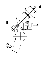
Adjustment of the dash pot
Adjust the lever position so that the lever and the dashpot contact at a deg (L mm) from the idle lever position.
A = dashpot
b = dashpot contact point
----------
a=8+-2deg L=5.2+-1mm
----------
L=4.2~6.2mm
----------
a=8+-2deg L=5.2+-1mm
----------
L=4.2~6.2mm
0000001901 W-CSD ADJUSTMENT
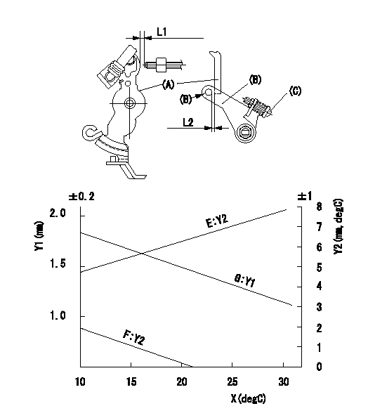
Adjustment of the W-CSD
Adjust for the ambient temperature at adjustment in accordance with the graph.
(1)Timer stroke: adjust according to graph.
(2)Fast idle (D): insert a block gauge L1 between the control lever (A) and the idle adjusting screw.
Adjust screw (C) so that clearance between the control lever (A) and the fast idle lever's pin (B) is L2 as determined from the graph.
Y1 = timer stroke
Y2 = control lever position
X = temperature
Y1 = timer stroke
Y2 = lever position
E = lever position (mm)
F = lever angle (deg)
G = timer stroke (mm)
----------
L1=5.3+-0.05mm
----------
L=5.3mm E=Y2=0.152X+4.29(mm) F=Y2=-(mm) G=Y1=-0.035X+2.2(mm)
----------
L1=5.3+-0.05mm
----------
L=5.3mm E=Y2=0.152X+4.29(mm) F=Y2=-(mm) G=Y1=-0.035X+2.2(mm)
0000002001 POTENTIOMETER ADJUSTMENT
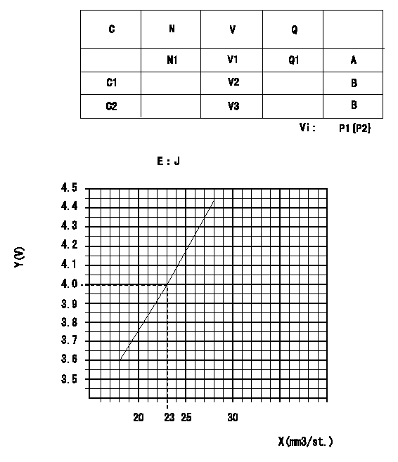
Adjustment of the potentiometer
In the following condition, change the installation position of the potentiometer to adjust the output voltage to within the specified values.
At N (pump speed) = N1 r/min and control lever position a (corresponding to shim thickness L mm), measure the injection quantity, calculate the voltage using the formula and adjust the potentiometer.
Vi:Applied voltage
C:Position of the control lever
N:Pump speed (r/min)
V:Output voltage (V)
Q:Injection quantity (mm3/st)
A:Adjusting point
B:Checking point
C1:Idle
C2:Full speed
P1:Boost pressure
P2:Boost pressure
E:Conversion formula
X:Injection quantity Q (cm3/1,000st)
Y:Voltage (V)
----------
N1=1000r/min a=19deg L=12.1mm
----------
N1=1000r/min V1=4+-0.03V V2=0.8+-0.7V V3=7.7+-1.2V Q1=22.9cm3/1,000st Vi=10V P1=-kPa P2=-mmHg J=V+-0.03=0.0856Q+2.04
----------
N1=1000r/min a=19deg L=12.1mm
----------
N1=1000r/min V1=4+-0.03V V2=0.8+-0.7V V3=7.7+-1.2V Q1=22.9cm3/1,000st Vi=10V P1=-kPa P2=-mmHg J=V+-0.03=0.0856Q+2.04
0000002101 BOOST COMPENSATOR ADJUSTMENT
BCS adjustment procedure
1. At pump speed N1 and boost pressure P1 confirm that the BCS moves through its full stroke and then adjust the injection quantity.
2. At pump speed N2 and boost pressure P2, adjust the full load injection quantity using the BCS spring set screw.
----------
N1=1250r/min N2=750r/min P1=78.6kPa(590mmHg) P2=33.3kPa(250mmHg)
----------
----------
N1=1250r/min N2=750r/min P1=78.6kPa(590mmHg) P2=33.3kPa(250mmHg)
----------
Information:
* Remove any carbon deposits from the injection nozzles before disassembling, assembling, or adjusting the injection nozzle assembly. Before disassembling, check the pressure and shape of the spray and inspect the assembly for fuel leakage. Do not disassemble if no defects are evident.* Do not change the needle valve and nozzle combination on each cylinder.
* Assembly sequenceFollow the disassembly sequence in reverse.Service standards Tightening torque (Unit: N m {kgf m}) Special tools (Unit: mm) Inspection before removal
Inspection: Injection nozzle* Connect the injection nozzle to the nozzle tester and carry out the following inspections.
* Before starting the inspections, operate the lever on the nozzle tester two or three times to bleed out all the air.
(1) Checking the valve opening pressure* Push down the lever on the nozzle tester at a rate of one to two seconds per stroke. This will cause the pressure gauge reading to rise gradually, and the needle will suddenly deflect. Note the pressure at which the needle starts to deflect. * If the measurement is out of the standard value range, disassemble the nozzle, clean it, and then adjust it using an adjusting shim.* Available adjusting shims (thickness): 1.2 mm to 1.7 mm (11 different thicknesses in increments of 0.05 mm)* If the valve opening pressure is still incorrect after the adjustment, replace the injection nozzle assembly.
* Do not touch the spray that comes out of the nozzle.
(2) Inspecting the spray condition * Pump the lever on the nozzle at a rate of about one to two seconds per stroke and keep it spraying continuously.A Spray in the form of straight line (Good: spray angle at 10° or less)B Spray angle too large (Bad)C Spray deviates from centerline (Bad)D Irregular spray (Bad)
* Do not touch the spray that comes out of the nozzle.
* Check that no fuel drips from the nozzle after the spray is complete.* If defects are evident, disassemble and clean the injection nozzle, and then inspect its spray condition once again.* If defects persist after reinspection, replace the injection nozzle assembly.(3) Checking for leakage * Decrease the nozzle pressure to a pressure 1960 kPa {20 kgf/cm2} lower than the first valve opening pressure. Maintain this pressure for 10 seconds and check that no fuel drips from the end of the nozzle.* If fuel drips are evident, disassemble and clean the injection nozzle, and then perform a leakage test once again.* If leakage is detected during the reinspection, replace the injection nozzle assembly.Removal procedure
Removal: Injection nozzle
* Do not touch the sliding surfaces of the needle valve. If you accidentally touch it, clean it with a cleaning fluid (such as gas oil).* Do not change the needle valve and nozzle combination on each cylinder.
Cleaning procedure
Cleaning: Injection nozzle* Wash the needle valve and nozzle in a cleaning fluid (such as gas oil), then use
to remove any carbon deposits according to the following procedure. * Remove carbon deposits from the tip of the needle valve using the clean bar of
.
* Do not use a wire brush