Information injection-pump assembly
BOSCH
9 460 610 079
9460610079
ZEXEL
104749-3010
1047493010
MITSUBISHI
MD077258
md077258
Rating:
Cross reference number
BOSCH
9 460 610 079
9460610079
ZEXEL
104749-3010
1047493010
MITSUBISHI
MD077258
md077258
Zexel num
Bosch num
Firm num
Name
9 460 610 079
MD077258 MITSUBISHI
INJECTION-PUMP ASSEMBLY
4D6 K 11CJ INJECTION PUMP ASSY VE4 VE
4D6 K 11CJ INJECTION PUMP ASSY VE4 VE
Calibration Data:
Adjustment conditions
Test oil
1404 Test oil ISO4113orSAEJ967d
1404 Test oil ISO4113orSAEJ967d
Test oil temperature
degC
45
45
50
Nozzle
105000-2010
Bosch type code
NP-DN12SD12TT
Nozzle holder
105780-2080
Opening pressure
MPa
14.7
14.7
15.19
Opening pressure
kgf/cm2
150
150
155
Injection pipe
Inside diameter - outside diameter - length (mm) mm 2-6-840
Inside diameter - outside diameter - length (mm) mm 2-6-840
Transfer pump pressure
kPa
20
20
20
Transfer pump pressure
kgf/cm2
0.2
0.2
0.2
Direction of rotation (viewed from drive side)
Right R
Right R
Injection timing adjustment
Pump speed
r/min
1250
1250
1250
Boost pressure
kPa
78.65
77.3
80
Boost pressure
mmHg
590
580
600
Average injection quantity
mm3/st.
46.8
46.3
47.3
Difference in delivery
mm3/st.
3
Basic
*
Injection timing adjustment_02
Pump speed
r/min
750
750
750
Boost pressure
kPa
33.35
32
34.7
Boost pressure
mmHg
250
240
260
Average injection quantity
mm3/st.
40.7
40.2
41.2
Difference in delivery
mm3/st.
3
Basic
*
Injection timing adjustment_03
Pump speed
r/min
2750
2750
2750
Boost pressure
kPa
0
0
0
Boost pressure
mmHg
0
0
0
Average injection quantity
mm3/st.
6.5
1.5
11.5
Injection timing adjustment_04
Pump speed
r/min
2250
2250
2250
Boost pressure
kPa
78.65
77.3
80
Boost pressure
mmHg
590
580
600
Average injection quantity
mm3/st.
40.7
38.2
43.2
Injection timing adjustment_05
Pump speed
r/min
1250
1250
1250
Boost pressure
kPa
78.65
77.3
80
Boost pressure
mmHg
590
580
600
Average injection quantity
mm3/st.
46.8
45.8
47.8
Injection timing adjustment_06
Pump speed
r/min
750
750
750
Boost pressure
kPa
33.35
32
34.7
Boost pressure
mmHg
250
240
260
Average injection quantity
mm3/st.
40.7
39.7
41.7
Injection timing adjustment_07
Pump speed
r/min
600
600
600
Boost pressure
kPa
0
0
0
Boost pressure
mmHg
0
0
0
Average injection quantity
mm3/st.
35.2
32.7
37.7
Injection quantity adjustment
Pump speed
r/min
2750
2750
2750
Boost pressure
kPa
0
0
0
Boost pressure
mmHg
0
0
0
Average injection quantity
mm3/st.
6.5
3.5
9.5
Difference in delivery
mm3/st.
2
Basic
*
Injection quantity adjustment_02
Pump speed
r/min
3000
3000
3000
Boost pressure
kPa
0
0
0
Boost pressure
mmHg
0
0
0
Average injection quantity
mm3/st.
3
Governor adjustment
Pump speed
r/min
400
400
400
Boost pressure
kPa
0
0
0
Boost pressure
mmHg
0
0
0
Average injection quantity
mm3/st.
6.5
5
8
Difference in delivery
mm3/st.
2
Basic
*
Governor adjustment_02
Pump speed
r/min
600
600
600
Boost pressure
kPa
0
0
0
Boost pressure
mmHg
0
0
0
Average injection quantity
mm3/st.
2
Governor adjustment_03
Pump speed
r/min
400
400
400
Boost pressure
kPa
0
0
0
Boost pressure
mmHg
0
0
0
Average injection quantity
mm3/st.
6.5
4.5
8.5
Timer adjustment
Pump speed
r/min
100
100
100
Boost pressure
kPa
0
0
0
Boost pressure
mmHg
0
0
0
Average injection quantity
mm3/st.
53
43
63
Basic
*
Speed control lever angle
Pump speed
r/min
400
400
400
Boost pressure
kPa
0
0
0
Boost pressure
mmHg
0
0
0
Average injection quantity
mm3/st.
0
0
0
Remarks
Magnet OFF
Magnet OFF
0000000901
Pump speed
r/min
1250
1250
1250
Boost pressure
kPa
78.65
77.3
80
Boost pressure
mmHg
590
580
600
Overflow quantity
cm3/min
420
288
552
Stop lever angle
Pump speed
r/min
1250
1250
1250
Boost pressure
kPa
78.65
77.3
80
Boost pressure
mmHg
590
580
600
Pressure
kPa
470.5
441
500
Pressure
kgf/cm2
4.8
4.5
5.1
Basic
*
Stop lever angle_02
Pump speed
r/min
600
600
600
Boost pressure
kPa
78.65
77.3
80
Boost pressure
mmHg
590
580
600
Pressure
kPa
313.5
284
343
Pressure
kgf/cm2
3.2
2.9
3.5
Stop lever angle_03
Pump speed
r/min
1250
1250
1250
Boost pressure
kPa
78.65
77.3
80
Boost pressure
mmHg
590
580
600
Pressure
kPa
470.5
441
500
Pressure
kgf/cm2
4.8
4.5
5.1
Stop lever angle_04
Pump speed
r/min
2250
2250
2250
Boost pressure
kPa
78.65
77.3
80
Boost pressure
mmHg
590
580
600
Pressure
kPa
696.5
667
726
Pressure
kgf/cm2
7.1
6.8
7.4
0000001101
Pump speed
r/min
1250
1250
1250
Boost pressure
kPa
78.65
77.3
80
Boost pressure
mmHg
590
580
600
Timer stroke
mm
4.1
3.9
4.3
Basic
*
_02
Pump speed
r/min
600
600
600
Boost pressure
kPa
78.65
77.3
80
Boost pressure
mmHg
590
580
600
Timer stroke
mm
1.3
0.7
1.9
_03
Pump speed
r/min
1250
1250
1250
Boost pressure
kPa
78.65
77.3
80
Boost pressure
mmHg
590
580
600
Timer stroke
mm
4.1
3.7
4.5
_04
Pump speed
r/min
1750
1750
1750
Boost pressure
kPa
78.65
77.3
80
Boost pressure
mmHg
590
580
600
Timer stroke
mm
6.2
5.6
6.8
_05
Pump speed
r/min
2250
2250
2250
Boost pressure
kPa
78.65
77.3
80
Boost pressure
mmHg
590
580
600
Timer stroke
mm
8.2
7.6
8.8
0000001201
Max. applied voltage
V
8
8
8
Test voltage
V
13
12
14
0000001401
Pump speed
r/min
1250
1250
1250
Boost pressure
kPa
0
0
0
Boost pressure
mmHg
0
0
0
Average injection quantity
mm3/st.
33.2
32.2
34.2
Timer stroke variation dT
mm
0.6
0.4
0.8
Basic
*
_02
Pump speed
r/min
1250
1250
1250
Boost pressure
kPa
0
0
0
Boost pressure
mmHg
0
0
0
Average injection quantity
mm3/st.
33.2
31.7
34.7
Timer stroke TA
mm
3.5
3.5
3.5
Timer stroke variation dT
mm
0.6
0.2
1
_03
Pump speed
r/min
1250
1250
1250
Boost pressure
kPa
0
0
0
Boost pressure
mmHg
0
0
0
Average injection quantity
mm3/st.
25.2
23.7
26.7
Timer stroke TA
mm
2.9
2.3
3.5
Timer stroke variation dT
mm
1.2
1.2
1.2
Timing setting
K dimension
mm
3.3
3.2
3.4
KF dimension
mm
5.8
5.7
5.9
MS dimension
mm
1
0.9
1.1
BCS stroke
mm
3.6
3.5
3.7
Control lever angle alpha
deg.
59
55
63
Control lever angle beta
deg.
41
36
46
Test data Ex:
0000001601 BCS ADJUSTMENT
BCS adjustment procedure
1. At pump speed N1 and boost pressure P1 confirm that the BCS moves through its full stroke and then adjust the injection quantity.
2. At pump speed N2 and boost pressure P2, adjust the full load injection quantity using the BCS spring set screw.
----------
N1=1250r/min N2=750r/min P1=78.6kPa(590mmHg) P2=33.3kPa(250mmHg)
----------
----------
N1=1250r/min N2=750r/min P1=78.6kPa(590mmHg) P2=33.3kPa(250mmHg)
----------
0000001801 DASHPOT ADJUSTMENT
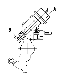
Adjustment of the dash pot
Adjust the lever position so that the lever and the dashpot contact at a deg (L mm) from the idle lever position.
A = dashpot
b = dashpot contact point
----------
a=12+-2deg L=7.6+-1mm
----------
L=7.6+-1mm
----------
a=12+-2deg L=7.6+-1mm
----------
L=7.6+-1mm
0000001901 W-CSD ADJUSTMENT
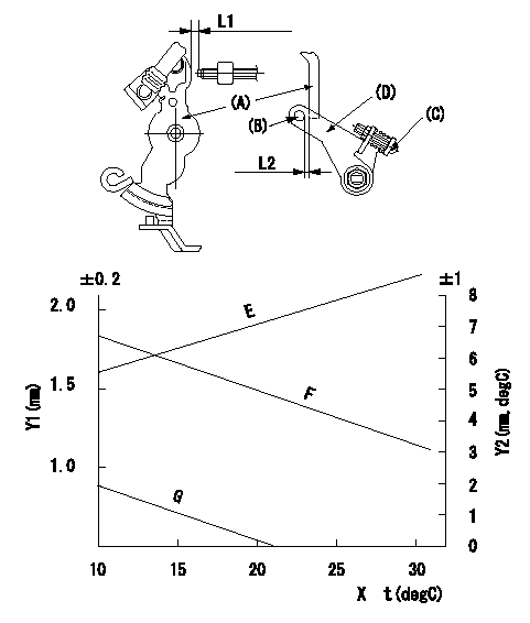
Adjustment of the W-CSD
Adjust for the ambient temperature at adjustment in accordance with the graph.
(1)adjust according to graph.
(2)Insert a block gauge L1 between the control lever (A) and the idle adjusting screw.
(3)Adjust screw (C) so that clearance between the control lever and the fast idle lever(D)'s pin (B) is L2 as determined from the graph.
Y1 = timer stroke
Y2 = control lever position
X = temperature t
Y1 = timer stroke (mm)
Y2 = lever position (mm)
Graph E=0.152t+4.29
Graph F=-0.035t+2.2
G=-
----------
L1=5.3+-0.05mm
----------
----------
L1=5.3+-0.05mm
----------
Information:
* Be sure to orient the oil grooves as indicated above, otherwise seizures may occur in the engine.
* Use oversize thrust plates when adjusting the crankshaft end play. The upper and lower thrust plates on the same side must be of the same size. The thrust plates on one side may differ in size from those on the other side. Installation: Main bearings
* The upper main bearing has an oil hole while the lower main bearing does not. Do not confuse the two, as incorrect installation can cause seizures in the engine.
* Select and use a main bearing set of a thickness that can accommodate the inside diameter of each main bearing fitting hole between the upper crankcase and lower crankcase and the diameter of the corresponding crankshaft journal. Select the appropriate main bearing set by one of the two following methods.(1) Measurement based selection* Mount the upper crankcase on the lower crankcase without fitting main bearings. * Tighten the main cap bolts to 20 N m {2.0 kgf m}.* Measure the inside diameter of the main bearing fitting hole between the upper crankcase and lower crankcase (vertically from one point), and the diameter of the crankshaft journal (vertically or horizontally from one point).* Select a main bearing set that matches the measurements from the table below. If the color identification mark is indiscernible, measure the thickness of the bearing walls and use the measurements in its place. (Unit: mm) (2) Color identification mark based method* The crankshaft, upper crankcase, and main bearing can be appropriately combined in the following ways according to their color identification marks: No. 1: Position of color identification mark on No. 1 journalNo. 2: Position of color identification mark on No. 2 journalNo. 3: Position of color identification mark on No. 3 journalNo. 4: Position of color identification mark on No. 4 journalNo. 5: Position of color identification mark on No. 5 journal Installation: Lower crankcase
* Before installing the main cap bolt, check the punch marks on each bolt's head. (Bolts with one or two punch marks can be reused.)* The punch marks indicate the number of times each main cap bolt has been tightened using the torque-turn tightening method. Any main cap bolt that already has three punch marks must be replaced.
* Clean the sealant application surfaces of each part. * Apply a bead of sealant to the upper crankcase evenly and without any breaks as shown in the illustration.* Install the lower crankcase within three minutes of applying the sealant to the upper crankcase, being careful not to dislodge the sealant.* Apply engine oil to the threads and seating surface under the head of each of the main cap bolts, and tighten the bolts to a torque of 20 N m {2.0 kgf m} in the order indicated in the illustration (1 to 10). * Then, tighten the main cap bolts further by 90 degrees in the same order.* Tighten them by another 90 degrees in the same order.* After completing