Information injection-pump assembly
BOSCH
9 460 610 078
9460610078
ZEXEL
104749-3000
1047493000
MITSUBISHI
MD074608
md074608
Rating:
Cross reference number
BOSCH
9 460 610 078
9460610078
ZEXEL
104749-3000
1047493000
MITSUBISHI
MD074608
md074608
Zexel num
Bosch num
Firm num
Name
104749-3000
9 460 610 078
MD074608 MITSUBISHI
INJECTION-PUMP ASSEMBLY
4D6 K
4D6 K
Calibration Data:
Adjustment conditions
Test oil
1404 Test oil ISO4113orSAEJ967d
1404 Test oil ISO4113orSAEJ967d
Test oil temperature
degC
45
45
50
Nozzle
105000-2010
Bosch type code
NP-DN12SD12TT
Nozzle holder
105780-2080
Opening pressure
MPa
14.7
14.7
15.19
Opening pressure
kgf/cm2
150
150
155
Injection pipe
Inside diameter - outside diameter - length (mm) mm 2-6-840
Inside diameter - outside diameter - length (mm) mm 2-6-840
Transfer pump pressure
kPa
20
20
20
Transfer pump pressure
kgf/cm2
0.2
0.2
0.2
Direction of rotation (viewed from drive side)
Right R
Right R
Injection timing adjustment
Pump speed
r/min
1250
1250
1250
Average injection quantity
mm3/st.
34.7
34.2
35.2
Difference in delivery
mm3/st.
3
Basic
*
Injection timing adjustment_02
Pump speed
r/min
600
600
600
Average injection quantity
mm3/st.
30.7
28.7
32.7
Injection timing adjustment_03
Pump speed
r/min
1250
1250
1250
Average injection quantity
mm3/st.
34.7
33.7
35.7
Injection timing adjustment_04
Pump speed
r/min
2250
2250
2250
Average injection quantity
mm3/st.
31.2
29.2
33.2
Injection timing adjustment_05
Pump speed
r/min
2750
2750
2750
Average injection quantity
mm3/st.
6.5
1.5
11.5
Injection quantity adjustment
Pump speed
r/min
2750
2750
2750
Average injection quantity
mm3/st.
6.5
3.5
9.5
Difference in delivery
mm3/st.
2
Basic
*
Injection quantity adjustment_02
Pump speed
r/min
3000
3000
3000
Average injection quantity
mm3/st.
3
Governor adjustment
Pump speed
r/min
375
375
375
Average injection quantity
mm3/st.
6.5
5
8
Difference in delivery
mm3/st.
2
Basic
*
Governor adjustment_02
Pump speed
r/min
375
375
375
Average injection quantity
mm3/st.
8
6
10
Governor adjustment_03
Pump speed
r/min
600
600
600
Average injection quantity
mm3/st.
3
Timer adjustment
Pump speed
r/min
100
100
100
Average injection quantity
mm3/st.
53
43
63
Basic
*
Speed control lever angle
Pump speed
r/min
375
375
375
Average injection quantity
mm3/st.
0
0
0
Remarks
Magnet OFF
Magnet OFF
0000000901
Pump speed
r/min
1250
1250
1250
Overflow quantity
cm3/min
420
288
552
Stop lever angle
Pump speed
r/min
1250
1250
1250
Pressure
kPa
470.5
441
500
Pressure
kgf/cm2
4.8
4.5
5.1
Basic
*
Stop lever angle_02
Pump speed
r/min
600
600
600
Pressure
kPa
313.5
284
343
Pressure
kgf/cm2
3.2
2.9
3.5
Stop lever angle_03
Pump speed
r/min
1250
1250
1250
Pressure
kPa
470.5
441
500
Pressure
kgf/cm2
4.8
4.5
5.1
Stop lever angle_04
Pump speed
r/min
2250
2250
2250
Pressure
kPa
696.5
667
726
Pressure
kgf/cm2
7.1
6.8
7.4
0000001101
Pump speed
r/min
1250
1250
1250
Timer stroke
mm
4.3
4.1
4.5
Basic
*
_02
Pump speed
r/min
600
600
600
Timer stroke
mm
1.3
0.7
1.9
_03
Pump speed
r/min
1250
1250
1250
Timer stroke
mm
4.3
3.9
4.7
_04
Pump speed
r/min
2250
2250
2250
Timer stroke
mm
8.5
8
9
0000001201
Max. applied voltage
V
8
8
8
Test voltage
V
13
12
14
0000001401
Pump speed
r/min
1250
1250
1250
Average injection quantity
mm3/st.
21.6
20.6
22.6
Timer stroke variation dT
mm
0.5
0.3
0.7
Basic
*
_02
Pump speed
r/min
1250
1250
1250
Average injection quantity
mm3/st.
21.6
20.1
23.1
Timer stroke TA
mm
3.8
3.8
3.8
Timer stroke variation dT
mm
0.5
0.1
0.9
_03
Pump speed
r/min
1250
1250
1250
Average injection quantity
mm3/st.
11.6
10.1
13.1
Timer stroke TA
mm
3.1
2.5
3.7
Timer stroke variation dT
mm
1.2
1.2
1.2
Timing setting
K dimension
mm
3.3
3.2
3.4
KF dimension
mm
5.8
5.7
5.9
MS dimension
mm
1.4
1.3
1.5
Control lever angle alpha
deg.
59
55
63
Control lever angle beta
deg.
41
36
46
Test data Ex:
0000001801 DASHPOT ADJUSTMENT
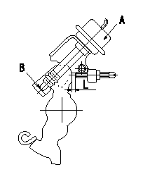
Adjustment of the dash pot
Adjust the lever position so that the lever and the dashpot contact at a deg (L mm) from the idle lever position.
A = dashpot
b = dashpot contact point
----------
a=10+-2deg L=6.3+-1mm
----------
L=6.3mm
----------
a=10+-2deg L=6.3+-1mm
----------
L=6.3mm
0000001901 W-CSD ADJUSTMENT
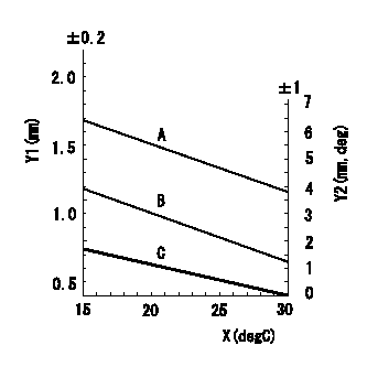
Adjustment of the W-CSD
Adjust the timer stroke and the control lever position for the ambient temperature at adjustment in accordance with the figure below.
Y1 = timer stroke
Y2 = control lever position
X = temperature
A = timer stroke
B = lever position
----------
----------
----------
----------
Information:
Precautions for Electrical System
* Before working on the electrical system, disconnect the (-) battery cable to prevent short circuits.
* Make sure the electrical equipment is OFF before disconnecting or connecting battery cable. Semiconductor components may otherwise be damaged.
* Carefully handle sensors relays, and other items that are sensitive to shock and heat. * When applying a voltage to a part for inspection purposes, check that the (+) and (-) cables are connected properly then gradually increase the voltage from zero. Do not exceed the specified voltage. Remember that sensors do not necessarily operate on the battery voltage. * When separating connectors, grasp the connectors themselves rather than the harnesses. * To separate locking connectors, first push them in the direction of the arrows. To reconnect locking connectors, push them together until they click.* Before washing the parts, cover electrical parts to keep them dry. (Use plastic sheets or the like.) Keep water away from harness connectors and sensors and immediately wipe off any water that gets on them. Handling precautions for electric circuits
* Do not pierce wire insulation with test probes or alligator clips when performing electrical inspections. Doing so can, particularly with the chassis harness, hasten corrosion.
(1) Inspection of harnesses (1.1) Inspections with connectors fitted together* Waterproof connectors* Connect an inspection harness and connector. A between the connectors B of the circuit to be inspected. Perform the inspection by applying a test probe C to the connectors of the inspection harness. Do not insert the test probe C into the wire-entry sides of the waterproof connectors since this would damage their waterproof seals and lead to rust. * Non-waterproof connectors* Perform the inspection by inserting a test probe C into the wire-entry sides of the connectors. An extra-narrow probe is required for control unit connectors, which are smaller than other types of connector. Do not force a regular-size probe into control unit connectors since this would cause damage. (1.2) Inspections with connectors separated* Inspections on female terminals* Perform the inspection by carefully inserting a test probe into the terminals. Do not force the test probe into the terminals since this could deform them and cause poor connections. * Inspections on male terminals* Perform the inspection by applying test probes directly to the pins.
* Be careful not to short-circuit pins together with the test probes. With control unit connectors, short-circuiting of pins can cause damage to the control unit's internal circuitry.
* When using a multimeter to check continuity, do not allow the test probes to touch the wrong terminals. (2) Inspection of connectors (2.1) Visual inspection* Check that the connectors are fitted together securely. * Check whether wires have been separated from their terminals due to pulling of the harness. * Check that male and female terminals fit together tightly. * Check for defective connections caused by loose terminals, by rust on terminals, or by contamination of terminals by foreign substances. (2.2) Checking for loose terminals* If connector terminal retainers become damaged, male and female terminals may not
Have questions with 104749-3000?
Group cross 104749-3000 ZEXEL
Mitsubishi
104749-3000
9 460 610 078
MD074608
INJECTION-PUMP ASSEMBLY
4D6
4D6