Information injection-pump assembly
BOSCH
9 460 613 047
9460613047
ZEXEL
104749-2680
1047492680
NISSAN
1670039C10
1670039c10
Rating:
Components :
| 0. | INJECTION-PUMP ASSEMBLY | 104749-2680 |
| 1. | _ | |
| 2. | FUEL INJECTION PUMP | 104649-2680 |
| 3. | NUMBER PLATE | 146915-3500 |
| 4. | _ | |
| 5. | CAPSULE | |
| 6. | ADJUSTING DEVICE | |
| 7. | NOZZLE AND HOLDER ASSY | 105141-2422 |
| 8. | Nozzle and Holder | 16600-05E12 |
| 9. | Open Pre:MPa(Kqf/cm2) | 12.7{130} |
| 10. | NOZZLE-HOLDER | 105071-0681 |
| 11. | NOZZLE | 105000-1871 |
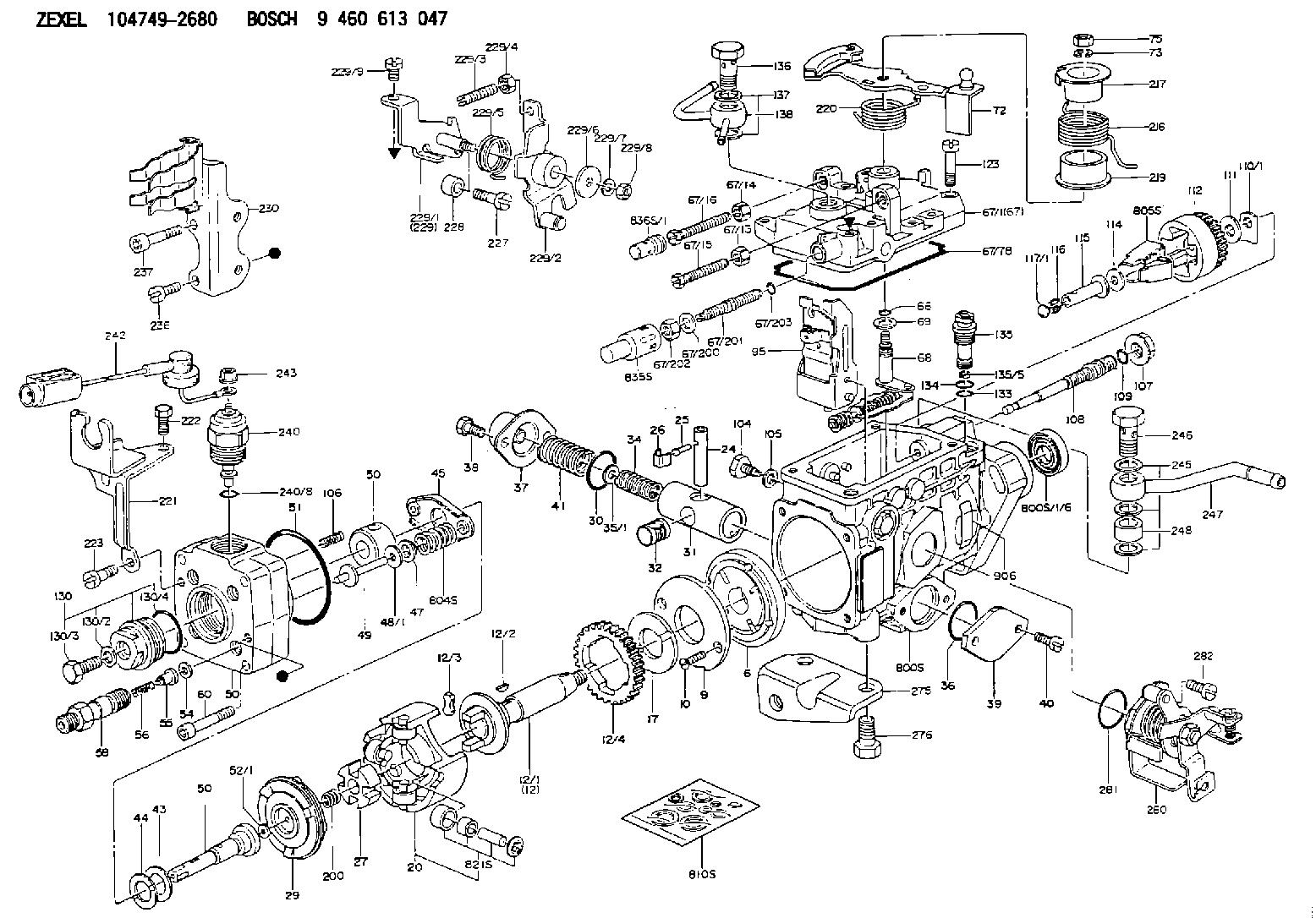
Scheme ###:
| 1/6. | [1] | 146601-0700 | PACKING RING |
| 6. | [1] | 146100-0220 | SUPPLY PUMP |
| 9. | [1] | 146103-0100 | COVER |
| 10. | [2] | 139104-0000 | FLAT-HEAD SCREW |
| 12. | [1] | 146200-0420 | DRIVE SHAFT |
| 12/1. | [1] | 146200-0400 | DRIVE SHAFT |
| 12/2. | [1] | 146201-0000 | WOODRUFF KEY |
| 12/3. | [2] | 146202-0100 | DAMPER |
| 12/4. | [1] | 146203-0000 | TOOTHED GEAR |
| 17. | [1] | 146204-0000 | PLAIN WASHER |
| 20. | [1] | 146210-1820 | ROLLER SET |
| 24. | [1] | 146303-0000 | BEARING PIN |
| 25. | [1] | 146304-0000 | BEARING PIN |
| 26. | [1] | 146305-0000 | CLAMPING BAND |
| 27. | [1] | 146205-0000 | SLOTTED WASHER |
| 29. | [1] | 146220-2120 | CAM PLATE |
| 30. | [1] | 146600-0800 | O-RING |
| 31. | [1] | 146311-6520 | PUMP PLUNGER |
| 32. | [1] | 146301-0000 | SLIDING PIECE |
| 34. | [1] | 146312-2500 | COMPRESSION SPRING |
| 34B. | [1] | 146312-2600 | COMPRESSION SPRING |
| 35/1. | [1] | 146690-3200 | SHIM D11.5&9.4T0.1 |
| 35/1. | [1] | 146690-3300 | SHIM D11.5&9.4T0.2 |
| 35/1. | [1] | 146690-3400 | SHIM D11.5&9.4T0.25 |
| 35/1. | [1] | 146690-3500 | SHIM D11.5&9.4T1.0 |
| 35/1. | [1] | 146690-4100 | SHIM D11.5&9.4T2 |
| 35/1. | [1] | 146690-4200 | SHIM D11.5&9.4T0.5 |
| 35/1. | [1] | 146690-4300 | SHIM D11.5&9.4T0.75 |
| 36. | [1] | 146600-0800 | O-RING |
| 37. | [1] | 146310-4020 | COVER |
| 38. | [2] | 146620-5000 | BLEEDER SCREW |
| 39. | [1] | 146310-0100 | COVER |
| 40. | [2] | 146620-5000 | BLEEDER SCREW |
| 41. | [1] | 146312-1900 | COMPRESSION SPRING |
| 43. | [1] | 146230-0000 | SHIM |
| 44. | [1] | 146230-0100 | PLAIN WASHER |
| 45. | [1] | 146231-0001 | SLOTTED WASHER |
| 47. | [2] | 146233-0000 | SLOTTED WASHER |
| 48/1. | [1] | 146603-0000 | SHIM D17.0&5.2T0.50 |
| 48/1. | [1] | 146603-0100 | SHIM D17.0&5.2T0.80 |
| 48/1. | [1] | 146603-0200 | SHIM D17.0&5.2T1.00 |
| 48/1. | [1] | 146603-0300 | SHIM D17.0&5.2T1.20 |
| 48/1. | [1] | 146603-0400 | SHIM D17.0&5.2T1.50 |
| 48/1. | [1] | 146603-0500 | SHIM D17.0&5.2T1.80 |
| 48/1. | [1] | 146603-0600 | SHIM D17.0&5.2T2.00 |
| 48/1. | [1] | 146690-1400 | SHIM D17&5.2T0.9 |
| 48/1. | [1] | 146690-1500 | SHIM D17&5.2T1.1 |
| 48/1. | [1] | 146690-1600 | SHIM D17&5.2T1.3 |
| 48/1. | [1] | 146690-1700 | SHIM D17&5.2T1.4 |
| 48/1. | [1] | 146690-1800 | SHIM D17&5.2T1.6 |
| 48/1. | [1] | 146690-1900 | SHIM D17&5.2T1.7 |
| 48/1. | [1] | 146690-5800 | SHIM |
| 48/1. | [1] | 146690-5900 | SHIM |
| 48/1. | [1] | 146690-6000 | SHIM |
| 48/1. | [1] | 146690-6100 | SHIM |
| 48/1. | [1] | 146690-6200 | SHIM |
| 48/1. | [1] | 146690-6300 | SHIM |
| 48/1. | [1] | 146690-6400 | SHIM |
| 48/1. | [1] | 146690-6500 | SHIM |
| 48/1. | [1] | 146690-6600 | SHIM |
| 48/1. | [1] | 146690-6700 | SHIM |
| 48/1. | [1] | 146690-6800 | SHIM |
| 48/1. | [1] | 146690-6900 | SHIM |
| 48/1. | [1] | 146690-7000 | SHIM |
| 48/1. | [1] | 146690-7100 | SHIM |
| 48/1. | [1] | 146690-7200 | SHIM |
| 48/1. | [1] | 146690-7300 | SHIM |
| 48/1. | [1] | 146690-7400 | SHIM |
| 48/1. | [1] | 146690-7500 | SHIM |
| 48/1. | [1] | 146690-7800 | SHIM |
| 49. | [2] | 146234-0500 | GUIDE PIN |
| 50. | [1] | 146400-6820 | HYDRAULIC HEAD |
| 50. | [1] | 146400-6820 | HYDRAULIC HEAD |
| 50. | [1] | 146400-6820 | HYDRAULIC HEAD |
| 51. | [1] | 146600-0000 | O-RING |
| 52/1. | [1] | 146420-0000 | SHIM D9.5&3.0T1.90 |
| 52/1. | [1] | 146420-0100 | SHIM D9.5&3.0T1.92 |
| 52/1. | [1] | 146420-0200 | SHIM D9.5&3.0T1.94 |
| 52/1. | [1] | 146420-0300 | SHIM D9.5&3.0T1.96 |
| 52/1. | [1] | 146420-0400 | SHIM D9.5&3.0T1.98 |
| 52/1. | [1] | 146420-0500 | SHIM D9.5&3.0T2.00 |
| 52/1. | [1] | 146420-0600 | SHIM D9.5&3.0T2.02 |
| 52/1. | [1] | 146420-0700 | SHIM D9.5&3.0T2.04 |
| 52/1. | [1] | 146420-0800 | SHIM D9.5&3.0T2.06 |
| 52/1. | [1] | 146420-0900 | SHIM D9.5&3.0T2.08 |
| 52/1. | [1] | 146420-1000 | SHIM D9.5&3.0T2.10 |
| 52/1. | [1] | 146420-1100 | SHIM D9.5&3.0T2.12 |
| 52/1. | [1] | 146420-1200 | SHIM D9.5&3.0T2.14 |
| 52/1. | [1] | 146420-1300 | SHIM D9.5&3.0T2.16 |
| 52/1. | [1] | 146420-1400 | SHIM D9.5&3.0T2.18 |
| 52/1. | [1] | 146420-1500 | SHIM D9.5&3.0T2.20 |
| 52/1. | [1] | 146420-1600 | SHIM D9.5&3.0T2.22 |
| 52/1. | [1] | 146420-1700 | SHIM D9.5&3.0T2.24 |
| 52/1. | [1] | 146420-1800 | SHIM D9.5&3.0T2.26 |
| 52/1. | [1] | 146420-1900 | SHIM D9.5&3.0T2.28 |
| 52/1. | [1] | 146420-2000 | SHIM D9.5&3.0T2.30 |
| 52/1. | [1] | 146420-2100 | SHIM D9.5&3.0T2.32 |
| 52/1. | [1] | 146420-2200 | SHIM D9.5&3.0T2.34 |
| 52/1. | [1] | 146420-2300 | SHIM D9.5&3.0T2.36 |
| 52/1. | [1] | 146420-2400 | SHIM D9.5&3.0T2.38 |
| 52/1. | [1] | 146420-2500 | SHIM D9.5&3.0T2.40 |
| 52/1. | [1] | 146420-2600 | SHIM D9.5&3.0T2.42 |
| 52/1. | [1] | 146420-2700 | SHIM D9.5&3.0T2.44 |
| 52/1. | [1] | 146420-2800 | SHIM D9.5&3.0T2.46 |
| 52/1. | [1] | 146420-2900 | SHIM D9.5&3.0T2.48 |
| 52/1. | [1] | 146420-3000 | SHIM D9.5&3.0T2.50 |
| 52/1. | [1] | 146420-3100 | SHIM D9.5&3.0T2.52 |
| 52/1. | [1] | 146420-3200 | SHIM D9.5&3.0T2.54 |
| 52/1. | [1] | 146420-3300 | SHIM D9.5&3.0T2.56 |
| 52/1. | [1] | 146420-3400 | SHIM D9.5&3.0T2.58 |
| 52/1. | [1] | 146420-3500 | SHIM D9.5&3.0T2.60 |
| 52/1. | [1] | 146420-3600 | SHIM D9.5&3.0T2.62 |
| 52/1. | [1] | 146420-3700 | SHIM D9.5&3.0T2.64 |
| 52/1. | [1] | 146420-3800 | SHIM D9.5&3.0T2.66 |
| 52/1. | [1] | 146420-3900 | SHIM D9.5&3.0T2.68 |
| 52/1. | [1] | 146420-4000 | SHIM D9.5&3.0T2.70 |
| 52/1. | [1] | 146420-4100 | SHIM D9.5&3.0T2.72 |
| 52/1. | [1] | 146420-4200 | SHIM D9.5&3.0T2.74 |
| 52/1. | [1] | 146420-4300 | SHIM D9.5&3.0T2.76 |
| 52/1. | [1] | 146420-4400 | SHIM D9.5&3.0T2.78 |
| 52/1. | [1] | 146420-4500 | SHIM D9.5&3.0T2.80 |
| 52/1. | [1] | 146420-4600 | SHIM D9.5&3.0T2.82 |
| 52/1. | [1] | 146420-4700 | SHIM D9.5&3.0T2.84 |
| 52/1. | [1] | 146420-4800 | SHIM D9.5&3.0T2.86 |
| 52/1. | [1] | 146420-4900 | SHIM D9.5&3.0T2.88 |
| 52/1. | [1] | 146420-5000 | SHIM D9.5&3.0T2.90 |
| 52/1. | [1] | 146420-5100 | SHIM D9.5&3.0T1.74 |
| 52/1. | [1] | 146420-5200 | SHIM D9.5&3.0T1.76 |
| 52/1. | [1] | 146420-5300 | SHIM D9.5&3.0T1.78 |
| 52/1. | [1] | 146420-5400 | SHIM D9.5&3.0T1.80 |
| 52/1. | [1] | 146420-5500 | SHIM D9.5&3.0T1.82 |
| 52/1. | [1] | 146420-5600 | SHIM D9.5&3.0T1.84 |
| 52/1. | [1] | 146420-5700 | SHIM D9.5&3.0T1.86 |
| 52/1. | [1] | 146420-5800 | SHIM D9.5&3.0T1.88 |
| 54. | [4] | 146433-0100 | GASKET D12&6.4T1.00 |
| 55. | [4] | 146430-6220 | DELIVERY-VALVE ASSEMBLY |
| 56. | [4] | 146432-0000 | COMPRESSION SPRING |
| 58. | [4] | 146440-2720 | FITTING |
| 60. | [3] | 139106-0100 | FLAT-HEAD SCREW |
| 66. | [1] | 146600-0100 | O-RING |
| 67. | [1] | 146503-4320 | GOVERNOR COVER |
| 67/1. | [1] | 146508-2021 | GOVERNOR COVER |
| 67/13. | [1] | 013020-6040 | UNION NUT M6P1H5 |
| 67/14. | [1] | 146621-1700 | UNION NUT |
| 67/15. | [1] | 146526-2800 | BLEEDER SCREW |
| 67/16. | [1] | 146526-2800 | BLEEDER SCREW |
| 67/78. | [1] | 146600-4400 | SEAL RING |
| 67/200. | [1] | 139308-0300 | PLAIN WASHER |
| 67/201. | [1] | 146545-3720 | THREADED PIN |
| 67/202. | [1] | 139208-0900 | UNION NUT |
| 67/203. | [1] | 146600-1200 | O-RING |
| 68. | [1] | 146513-0920 | CONTROL SHAFT |
| 69. | [1] | 139310-0200 | PLAIN WASHER |
| 72. | [1] | 146535-1520 | CONTROL LEVER |
| 72B. | [1] | 146535-1620 | CONTROL LEVER |
| 73. | [1] | 014110-6440 | LOCKING WASHER |
| 75. | [1] | 013020-6040 | UNION NUT M6P1H5 |
| 95. | [1] | 146851-2120 | FULCRUM LEVER |
| 104. | [2] | 146568-0000 | SLOTTED SPRING PIN |
| 105. | [2] | 026508-1140 | GASKET D11.4&8.2T1 |
| 106. | [2] | 146588-0500 | COILED SPRING |
| 107. | [1] | 146569-0300 | UNION NUT |
| 108. | [1] | 146570-0100 | GOVERNOR SHAFT |
| 109. | [1] | 146600-0400 | O-RING |
| 110/1. | [1] | 146571-0000 | SHIM D20.2&8.3T1.05 |
| 110/1. | [1] | 146571-0100 | SHIM D20.2&8.3T1.25 |
| 110/1. | [1] | 146571-0200 | SHIM D20.2&8.3T1.45 |
| 110/1. | [1] | 146571-0300 | SHIM D20.2&8.3T1.65 |
| 110/1. | [1] | 146571-0400 | SHIM D20.2&8.3T1.85 |
| 110/1. | [1] | 146571-0500 | SHIM D20.2&8.3T1.15 |
| 110/1. | [1] | 146571-0600 | SHIM D20.2&8.3T1.35 |
| 110/1. | [1] | 146571-0700 | SHIM D20.2&8.3T1.55 |
| 110/1. | [1] | 146571-0800 | SHIM D20.2&8.3T1.75 |
| 111. | [1] | 146602-0600 | PLAIN WASHER D20&8.4T1.40 |
| 112. | [1] | 146572-0020 | FLYWEIGHT ASSEMBLY |
| 114. | [1] | 146602-0500 | PLAIN WASHER D17&6.4T1.60 |
| 115. | [1] | 146975-4200 | SLIDING SLEEVE |
| 116. | [1] | 146576-0200 | CAP |
| 117/1. | [1] | 146577-1800 | PLUG L2.10 |
| 117/1. | [1] | 146577-1900 | PLUG L2.30 |
| 117/1. | [1] | 146577-2000 | PLUG L2.50 |
| 117/1. | [1] | 146577-2100 | PLUG L2.70 |
| 117/1. | [1] | 146577-2200 | PLUG L2.90 |
| 117/1. | [1] | 146577-2300 | PLUG L3.10 |
| 117/1. | [1] | 146577-2400 | PLUG L3.30 |
| 117/1. | [1] | 146577-2500 | PLUG L3.50 |
| 117/1. | [1] | 146577-2600 | PLUG L3.70 |
| 117/1. | [1] | 146577-2700 | PLUG L3.90 |
| 117/1. | [1] | 146577-2800 | PLUG L4.10 |
| 117/1. | [1] | 146577-2900 | PLUG L4.30 |
| 117/1. | [1] | 146577-3000 | PLUG L4.50 |
| 117/1. | [1] | 146577-3100 | PLUG L4.70 |
| 117/1. | [1] | 146577-3200 | PLUG L4.90 |
| 117/1. | [1] | 146577-3300 | PLUG L5.10 |
| 117/1. | [1] | 146577-6700 | PLUG L2.2 |
| 117/1. | [1] | 146577-6800 | PLUG L2.4 |
| 117/1. | [1] | 146577-6900 | PLUG L2.6 |
| 117/1. | [1] | 146577-7000 | PLUG L2.8 |
| 117/1. | [1] | 146577-7100 | PLUG L3.0 |
| 117/1. | [1] | 146577-7200 | PLUG L3.2 |
| 117/1. | [1] | 146577-7300 | PLUG L3.4 |
| 117/1. | [1] | 146577-7400 | PLUG L3.6 |
| 117/1. | [1] | 146577-7500 | PLUG L3.8 |
| 117/1. | [1] | 146577-7600 | PLUG L4.0 |
| 117/1. | [1] | 146577-7700 | PLUG L4.2 |
| 117/1. | [1] | 146577-7800 | PLUG L4.4 |
| 117/1. | [1] | 146577-7900 | PLUG L4.6 |
| 117/1. | [1] | 146577-8000 | PLUG L4.8 |
| 117/1. | [1] | 146577-8100 | PLUG L5.0 |
| 117/1. | [1] | 146877-0000 | PLUG L5.2 |
| 117/1. | [1] | 146877-0100 | PLUG L5.3 |
| 117/1. | [1] | 146877-0200 | PLUG L5.4 |
| 117/1. | [1] | 146877-0300 | PLUG L5.5 |
| 117/1. | [1] | 146877-4700 | PLUG |
| 117/1. | [1] | 146877-4800 | PLUG |
| 117/1. | [1] | 146877-4900 | PLUG |
| 117/1. | [1] | 146877-5000 | PLUG |
| 123. | [4] | 139106-0200 | FLAT-HEAD SCREW |
| 130. | [1] | 146421-0020 | CAPSULE |
| 130/2. | [1] | 026508-1140 | GASKET D11.4&8.2T1 |
| 130/3. | [1] | 146422-0000 | BLEEDER SCREW |
| 130/4. | [1] | 146600-0500 | O-RING |
| 133. | [1] | 146600-0600 | O-RING |
| 134. | [1] | 146600-0700 | O-RING |
| 135. | [1] | 146110-0220 | CONTROL VALVE |
| 135/5. | [1] | 146114-0000 | SPRING WASHER |
| 136. | [1] | 146120-0220 | OVER FLOW VALVE |
| 137. | [2] | 139512-0200 | GASKET D18.5&12.2T1.00 |
| 138. | [1] | 146605-5520 | INLET UNION |
| 200. | [1] | 146206-0100 | COILED SPRING |
| 217. | [1] | 146541-2900 | SLOTTED WASHER |
| 218. | [1] | 146587-4900 | COILED SPRING |
| 219. | [1] | 146541-3000 | BUSHING |
| 220. | [1] | 146587-5000 | COILED SPRING |
| 221. | [1] | 146627-8320 | BRACKET |
| 222. | [1] | 139006-4600 | BLEEDER SCREW |
| 223. | [1] | 139006-4700 | BLEEDER SCREW |
| 227. | [1] | 010206-2040 | HEX-SOCKET-HEAD CAP SCREW |
| 228. | [1] | 146614-6700 | SPACER BUSHING |
| 229. | [1] | 146926-2120 | BRACKET |
| 229/1. | [1] | 146628-0510 | BRACKET |
| 229/2. | [1] | 146616-9520 | CONTROL LEVER |
| 229/3. | [1] | 146620-1400 | FLAT-HEAD SCREW |
| 229/4. | [1] | 013020-6040 | UNION NUT M6P1H5 |
| 229/5. | [1] | 146587-5100 | COILED SPRING |
| 229/6. | [1] | 146602-2000 | PLAIN WASHER D22&5.5T2 |
| 229/7. | [1] | 014110-5440 | LOCKING WASHER |
| 229/8. | [1] | 013020-5240 | UNION NUT M5P0.8H4 |
| 229/9. | [1] | 139006-4400 | BLEEDER SCREW |
| 230. | [1] | 146626-8920 | BRACKET |
| 236. | [1] | 139006-4800 | BLEEDER SCREW |
| 237. | [1] | 146620-0200 | HEX-SOCKET-HEAD CAP SCREW |
| 240. | [1] | 146650-0720 | PULLING ELECTROMAGNET |
| 240/8. | [1] | 146600-1700 | O-RING |
| 242. | [1] | 146658-2820 | WIRE |
| 243. | [1] | 146621-1000 | UNION NUT |
| 245. | [3] | 139512-0200 | GASKET D18.5&12.2T1.00 |
| 246. | [1] | 139812-0500 | EYE BOLT |
| 247. | [1] | 146605-8120 | INLET UNION |
| 248. | [1] | 146614-0200 | SPACER BUSHING |
| 275. | [1] | 146612-3920 | BRACKET |
| 276. | [2] | 010010-1640 | BLEEDER SCREW M10P1.5L16 4T |
| 280. | [1] | 146360-5020 | COVER |
| 281. | [1] | 146600-0800 | O-RING |
| 282. | [2] | 010206-1440 | HEX-SOCKET-HEAD CAP SCREW M6P1L14 |
| 800S. | [1] | 146019-5320 | PUMP HOUSING |
| 800S/1/6. | [1] | 146601-0700 | PACKING RING |
| 804S. | [1] | 146232-0220 | COMPRESSION SPRING |
| 805S. | [1] | 146574-0120 | PARTS SET |
| 810S. | [1] | 146600-1120 | REPAIR SET |
| 821S. | [1] | 146210-5720 | ROLLER SET |
| 835S. | [1] | 146598-1000 | CAP |
| 836S/1. | [1] | 146598-0600 | CAP L18 |
| 836S/1. | [1] | 146598-0700 | CAP L21 |
| 836S/1. | [1] | 146598-0800 | CAP L24 |
| 836S/1. | [1] | 146598-0900 | CAP L27 |
| 906. | [1] | 146915-3500 | NAMEPLATE |
Include in #2:
104749-2680
as INJECTION-PUMP ASSEMBLY
Cross reference number
BOSCH
9 460 613 047
9460613047
ZEXEL
104749-2680
1047492680
NISSAN
1670039C10
1670039c10
Zexel num
Bosch num
Firm num
Name
104749-2680
9 460 613 047
1670039C10 NISSAN
INJECTION-PUMP ASSEMBLY
LD20 K
LD20 K
Calibration Data:
Adjustment conditions
Test oil
1404 Test oil ISO4113orSAEJ967d
1404 Test oil ISO4113orSAEJ967d
Test oil temperature
degC
45
45
50
Nozzle
105780-0060
Bosch type code
NP-DN0SD1510
Nozzle holder
105780-2150
Opening pressure
MPa
13
13
13.3
Opening pressure
kgf/cm2
133
133
136
Injection pipe
157805-7320
Injection pipe
Inside diameter - outside diameter - length (mm) mm 2-6-450
Inside diameter - outside diameter - length (mm) mm 2-6-450
Joint assembly
157641-4720
Tube assembly
157641-4020
Transfer pump pressure
kPa
20
20
20
Transfer pump pressure
kgf/cm2
0.2
0.2
0.2
Direction of rotation (viewed from drive side)
Right R
Right R
Injection timing adjustment
Pump speed
r/min
900
900
900
Average injection quantity
mm3/st.
30.4
30
30.8
Difference in delivery
mm3/st.
2
Basic
*
Oil temperature
degC
50
48
52
Injection timing adjustment_02
Pump speed
r/min
600
600
600
Average injection quantity
mm3/st.
29.1
27.1
31.1
Oil temperature
degC
50
48
52
Injection timing adjustment_03
Pump speed
r/min
900
900
900
Average injection quantity
mm3/st.
28.9
27.9
29.9
Difference in delivery
mm3/st.
2.5
Basic
*
Oil temperature
degC
50
48
52
Injection timing adjustment_04
Pump speed
r/min
1200
1200
1200
Average injection quantity
mm3/st.
30.3
28.3
32.3
Oil temperature
degC
50
48
52
Injection timing adjustment_05
Pump speed
r/min
1800
1800
1800
Average injection quantity
mm3/st.
29.3
27.3
31.3
Oil temperature
degC
50
48
52
Injection timing adjustment_06
Pump speed
r/min
2300
2300
2300
Average injection quantity
mm3/st.
28
26
30
Oil temperature
degC
52
50
54
Injection quantity adjustment
Pump speed
r/min
2500
2500
2500
Average injection quantity
mm3/st.
16
14
18
Difference in delivery
mm3/st.
4.5
Basic
*
Oil temperature
degC
55
52
58
Injection quantity adjustment_02
Pump speed
r/min
2500
2500
2500
Average injection quantity
mm3/st.
14.2
10.7
17.7
Difference in delivery
mm3/st.
5
Basic
*
Oil temperature
degC
55
52
58
Injection quantity adjustment_03
Pump speed
r/min
2600
2600
2600
Average injection quantity
mm3/st.
6
Oil temperature
degC
55
52
58
Governor adjustment
Pump speed
r/min
350
350
350
Average injection quantity
mm3/st.
7.6
6.6
8.6
Difference in delivery
mm3/st.
2
Basic
*
Oil temperature
degC
48
46
50
Governor adjustment_02
Pump speed
r/min
350
350
350
Average injection quantity
mm3/st.
5.2
3.2
7.2
Difference in delivery
mm3/st.
2.5
Basic
*
Oil temperature
degC
48
46
50
Governor adjustment_03
Pump speed
r/min
500
500
500
Average injection quantity
mm3/st.
3
Oil temperature
degC
48
46
50
Boost compensator adjustment
Pump speed
r/min
600
600
600
Average injection quantity
mm3/st.
12.1
7.6
16.6
Oil temperature
degC
50
48
52
Lever angle (shim thickness)
mm
7.2
7.15
7.25
Boost compensator adjustment_02
Pump speed
r/min
900
900
900
Average injection quantity
mm3/st.
7
2
12
Oil temperature
degC
50
48
52
Lever angle (shim thickness)
mm
7.2
7.15
7.25
Timer adjustment
Pump speed
r/min
100
100
100
Average injection quantity
mm3/st.
54
44
64
Basic
*
Oil temperature
degC
48
46
50
Timer adjustment_02
Pump speed
r/min
100
100
100
Average injection quantity
mm3/st.
50
40
60
Oil temperature
degC
48
46
50
Speed control lever angle
Pump speed
r/min
350
350
350
Average injection quantity
mm3/st.
0
0
0
Oil temperature
degC
48
46
50
Remarks
Magnet OFF at idling position
Magnet OFF at idling position
Speed control lever angle_02
Pump speed
r/min
900
900
900
Average injection quantity
mm3/st.
0
0
0
Oil temperature
degC
50
48
52
Remarks
Magnet OFF at full-load position
Magnet OFF at full-load position
0000000901
Pump speed
r/min
900
900
900
Overflow quantity
cm3/min
330
200
460
Oil temperature
degC
50
48
52
Stop lever angle
Pump speed
r/min
900
900
900
Pressure
kPa
343
314
372
Pressure
kgf/cm2
3.5
3.2
3.8
Basic
*
Oil temperature
degC
50
48
52
Stop lever angle_02
Pump speed
r/min
900
900
900
Pressure
kPa
343
304
382
Pressure
kgf/cm2
3.5
3.1
3.9
Basic
*
Oil temperature
degC
50
48
52
Stop lever angle_03
Pump speed
r/min
1800
1800
1800
Pressure
kPa
539
500
578
Pressure
kgf/cm2
5.5
5.1
5.9
Oil temperature
degC
50
48
52
Stop lever angle_04
Pump speed
r/min
2500
2500
2500
Pressure
kPa
647
608
686
Pressure
kgf/cm2
6.6
6.2
7
Oil temperature
degC
52
50
54
0000001101
Pump speed
r/min
900
900
900
Timer stroke
mm
1.5
1.3
1.7
Basic
*
Oil temperature
degC
50
48
52
_02
Pump speed
r/min
900
900
900
Timer stroke
mm
1.5
1.2
1.8
Basic
*
Oil temperature
degC
50
48
52
_03
Pump speed
r/min
1200
1200
1200
Timer stroke
mm
3
2.6
3.4
Oil temperature
degC
50
48
52
_04
Pump speed
r/min
2300
2300
2300
Timer stroke
mm
8.6
7.8
9
Oil temperature
degC
52
50
54
0000001201
Max. applied voltage
V
8
8
8
Test voltage
V
13
12
14
Timing setting
K dimension
mm
3.3
3.2
3.4
KF dimension
mm
5.8
5.7
5.9
MS dimension
mm
1.2
1.1
1.3
Control lever angle alpha
deg.
25
21
29
Control lever angle beta
deg.
41
36
46
Test data Ex:
0000001801 M-CSD ADJUSTMENT
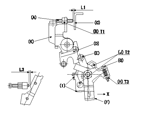
M-CSD adjustment
1. Fixing intermediate lever screw (A) [roller (E) must not contact intermediate lever (D)]
(1)Hold the control lever (C) in the idling position.
(2)At this time, adjust screw (A) so that it is horizontal and the clearance between screw (A) and the control lever (C) is L1. Then, fix using nut (B).
2. Fixing the M-CSD stopper (I)
Pull the CSD lever (F) in the direction X until it contacts the stopper (I) and tighten the socket head bolt (J) when the timer advance angle is L2.
3. Screw (G) adjustment
Pull the CSD lever (F) in the direction X until it contacts the stopper (I) and adjust the screw (G) so that the control lever shim thickness is L3. Then, tighten nut (H).
----------
L1=1~2mm L2=1.23+-0.2mm L3=7.2+-0.5mm
----------
T1=6~9N-m(0.6~0.9kgf-m) T2=5~7N-m(0.5~0.7kgf-m) T3=2~3N-m(0.2~0.3kgf-m) L1=1~2mm L3=7.2+-0.2mm
----------
L1=1~2mm L2=1.23+-0.2mm L3=7.2+-0.5mm
----------
T1=6~9N-m(0.6~0.9kgf-m) T2=5~7N-m(0.5~0.7kgf-m) T3=2~3N-m(0.2~0.3kgf-m) L1=1~2mm L3=7.2+-0.2mm
Information:
(b) 4.248 Engines (4 Ring)
**Spring Loaded Conformable Scraper - above gudgeon pin.Internally Stepped Compression - third groove.*Internally Stepped Compression - second groove.Chrome Insert Barrel Faced Compression - top groove.When fitting sealed power rings, ensure that the ends of the spring loaded segment butt together and do not overlap.**Some earlier A4.248 engines had a sealed power scraper ring fitted in the 4th groove. *On some earlier A4.248 engines rated up to 2,000 rev/min, the second compression ring is plain cast iron.Some later engines, rated up to 2,000 rev/min, have internally stepped chrome faced rings in both 2nd and 3rd grooves.When fitting internally stepped compression rings, ensure that the step is towards the piston crown.When fitting the spring loaded conformable scraper ring, ensure that the latch pin enters both ends of the spring. With the ring gap diametrically opposite to the latch pin, position the oil control ring over spring correctly located in annular groove of ring, i.e., between the oil control ring and the bottom of the ring groove in the piston.(c) 4.248 Engines (3 Ring)
Chrome Faced Spring Loaded ConformableScraper - above gudgeon pin.Internally Stepped Taper Faced Compression - second groove.Molybdenum Faced Internally Stepped Barrel Faced Compression - top groove.When fitting the spring loaded conformable scraper ring, ensure that the latch pin enters both ends of the spring. With the ring gap diametrically opposite to the latch pin, position the oil control ring over the spring correctly located in the annular groove of ring, i.e., between the oil control ring and the bottom of the ring groove in the piston.When fitting the internally stepped compression rings in the second and top grooves, ensure that the "step" is towards the piston crown.(d) T4.236 Engines (see Fig. F.6)
F6Chrome Faced Spring Loaded Conformable Scraper - above gudgeon pin.Cast Iron Taper Faced Compression - second groove.Molybdenum Faced Wedge Compression - top groove.When fitting the spring loaded conformable scraper ring, ensure that the latch pin enters both ends of the spring. With the ring gap diametrically opposite to the latch pin, position the oil control ring over spring correctly located in annular groove, i.e., between the oil control ring and the bottom of the ring groove in the piston.When fitting the compression rings, ensure that the manufacturers mark is towards the piston crown.(e) 4.236 Engines fitted with cast iron liners
Slotted Scraper - below gudgeon pin.Slotted Scraper - above gudgeon pin.Internally Stepped Compression - third groove.Internally Stepped Compression - second groove.*Chrome Faced Compression - top groove*With later combine engines, a plain cast iron ring is fitted in the top groove. This plain ring is completely interchangeable with the earlier chrome faced ring. When overhauling combine engines, the later plain ring should always be fitted (in engine sets). From Engine No. 236U68569 fitted to combine applications, some piston ring packs have been altered from five to four rings. The two slotted scraper rings fitted in the forth and fifth grooves have been replaced by one conformable chrome faced ring in the fourth groove only, leaving the
Have questions with 104749-2680?
Group cross 104749-2680 ZEXEL
Nissan
104749-2680
9 460 613 047
1670039C10
INJECTION-PUMP ASSEMBLY
LD20
LD20