Information injection-pump assembly
ZEXEL
104749-2441
1047492441
Rating:
Cross reference number
ZEXEL
104749-2441
1047492441
Zexel num
Bosch num
Firm num
Name
104749-2441
INJECTION-PUMP ASSEMBLY
Calibration Data:
Adjustment conditions
Test oil
1404 Test oil ISO4113orSAEJ967d
1404 Test oil ISO4113orSAEJ967d
Test oil temperature
degC
45
45
50
Nozzle
105000-2010
Bosch type code
NP-DN12SD12TT
Nozzle holder
105780-2080
Opening pressure
MPa
14.7
14.7
15.19
Opening pressure
kgf/cm2
150
150
155
Injection pipe
Inside diameter - outside diameter - length (mm) mm 2-6-840
Inside diameter - outside diameter - length (mm) mm 2-6-840
Transfer pump pressure
kPa
20
20
20
Transfer pump pressure
kgf/cm2
0.2
0.2
0.2
Direction of rotation (viewed from drive side)
Right R
Right R
Injection timing adjustment
Pump speed
r/min
900
900
900
Average injection quantity
mm3/st.
30.4
30
30.8
Difference in delivery
mm3/st.
2
Basic
*
Oil temperature
degC
50
48
52
Injection timing adjustment_02
Pump speed
r/min
600
600
600
Average injection quantity
mm3/st.
30.6
28.6
32.6
Oil temperature
degC
50
48
52
Injection timing adjustment_03
Pump speed
r/min
900
900
900
Average injection quantity
mm3/st.
30.4
29.4
31.4
Oil temperature
degC
50
48
52
Injection timing adjustment_04
Pump speed
r/min
1200
1200
1200
Average injection quantity
mm3/st.
31.8
29.8
33.8
Difference in delivery
mm3/st.
2.5
Basic
*
Oil temperature
degC
50
48
52
Injection timing adjustment_05
Pump speed
r/min
1800
1800
1800
Average injection quantity
mm3/st.
30.8
28.8
32.8
Oil temperature
degC
50
48
52
Injection timing adjustment_06
Pump speed
r/min
2300
2300
2300
Average injection quantity
mm3/st.
30.5
28.5
32.5
Oil temperature
degC
52
50
54
Injection timing adjustment_07
Pump speed
r/min
2500
2500
2500
Average injection quantity
mm3/st.
30.2
28.2
32.2
Oil temperature
degC
55
52
58
Injection quantity adjustment
Pump speed
r/min
2700
2700
2700
Average injection quantity
mm3/st.
14.5
12.5
16.5
Difference in delivery
mm3/st.
4.5
Basic
*
Oil temperature
degC
55
52
58
Injection quantity adjustment_02
Pump speed
r/min
2700
2700
2700
Average injection quantity
mm3/st.
14.5
11
18
Difference in delivery
mm3/st.
5
Basic
*
Oil temperature
degC
55
52
58
Injection quantity adjustment_03
Pump speed
r/min
2800
2800
2800
Average injection quantity
mm3/st.
6
Oil temperature
degC
55
52
58
Governor adjustment
Pump speed
r/min
350
350
350
Average injection quantity
mm3/st.
5.2
4.2
6.2
Difference in delivery
mm3/st.
2
Basic
*
Oil temperature
degC
48
46
50
Governor adjustment_02
Pump speed
r/min
350
350
350
Average injection quantity
mm3/st.
5.2
3.2
7.2
Difference in delivery
mm3/st.
2.5
Basic
*
Oil temperature
degC
48
46
50
Governor adjustment_03
Pump speed
r/min
500
500
500
Average injection quantity
mm3/st.
3
Oil temperature
degC
48
46
50
Boost compensator adjustment
Pump speed
r/min
600
600
600
Average injection quantity
mm3/st.
12.1
7.6
16.6
Oil temperature
degC
50
48
52
Lever angle (shim thickness)
mm
7.2
7.2
7.2
Boost compensator adjustment_02
Pump speed
r/min
900
900
900
Average injection quantity
mm3/st.
7
2
12
Oil temperature
degC
50
48
52
Lever angle (shim thickness)
mm
7.2
7.2
7.2
Timer adjustment
Pump speed
r/min
100
100
100
Average injection quantity
mm3/st.
50
40
60
Basic
*
Oil temperature
degC
48
46
50
Timer adjustment_02
Pump speed
r/min
100
100
100
Average injection quantity
mm3/st.
50
40
60
Oil temperature
degC
48
46
50
Speed control lever angle
Pump speed
r/min
350
350
350
Average injection quantity
mm3/st.
0
0
0
Oil temperature
degC
48
46
50
Remarks
Magnet OFF at idling position
Magnet OFF at idling position
Speed control lever angle_02
Pump speed
r/min
900
900
900
Average injection quantity
mm3/st.
0
0
0
Oil temperature
degC
50
48
52
Remarks
Magnet OFF at full-load position
Magnet OFF at full-load position
0000000901
Pump speed
r/min
900
900
900
Overflow quantity
cm3/min
330
200
460
Oil temperature
degC
50
48
52
Stop lever angle
Pump speed
r/min
900
900
900
Pressure
kPa
343
314
372
Pressure
kgf/cm2
3.5
3.2
3.8
Basic
*
Oil temperature
degC
50
48
52
Stop lever angle_02
Pump speed
r/min
900
900
900
Pressure
kPa
343
304
382
Pressure
kgf/cm2
3.5
3.1
3.9
Basic
*
Oil temperature
degC
50
48
52
Stop lever angle_03
Pump speed
r/min
1800
1800
1800
Pressure
kPa
539.5
500
579
Pressure
kgf/cm2
5.5
5.1
5.9
Oil temperature
degC
50
48
52
Stop lever angle_04
Pump speed
r/min
2300
2300
2300
Pressure
kPa
706
667
745
Pressure
kgf/cm2
7.2
6.8
7.6
Oil temperature
degC
52
50
54
0000001101
Pump speed
r/min
900
900
900
Timer stroke
mm
1.5
1.3
1.7
Basic
*
Oil temperature
degC
50
48
52
_02
Pump speed
r/min
900
900
900
Timer stroke
mm
1.5
1.2
1.8
Basic
*
Oil temperature
degC
50
48
52
_03
Pump speed
r/min
1200
1200
1200
Timer stroke
mm
3
2.7
3.3
Oil temperature
degC
50
48
52
_04
Pump speed
r/min
2300
2300
2300
Timer stroke
mm
8.4
7.8
9
Oil temperature
degC
52
50
54
0000001201
Max. applied voltage
V
8
8
8
Test voltage
V
13
12
14
Timing setting
K dimension
mm
3.3
3.2
3.4
KF dimension
mm
5.8
5.7
5.9
MS dimension
mm
1.2
1.1
1.3
Control lever angle alpha
deg.
25
21
29
Control lever angle beta
deg.
41
36
46
Test data Ex:
0000001801 POTENTIOMETER ADJUSTMENT
Adjustment of the potentiometer
(1)At pump speed N1 and oil temperature t, and at lever angle a from the idle position (shim thickness L), determine the voltage value from the graph using the injection quantity obtained. Then adjust the potentiometer.
V+-0.05 = 0.155323Q + 2.43145 (applied voltage Vi)
(2)With the control lever turned to the full speed side, confirm that voltage increases.
(3)Confirm V1 at idling.
Q:Injection quantity
----------
N1=600(r/min) t=48~52(deg) a=11(deg) L=7.2+-0.05(mm) Vi=10(V) V1=1.16+-0.9(V)
----------
----------
N1=600(r/min) t=48~52(deg) a=11(deg) L=7.2+-0.05(mm) Vi=10(V) V1=1.16+-0.9(V)
----------
0000001901 M-CSD ADJUSTMENT
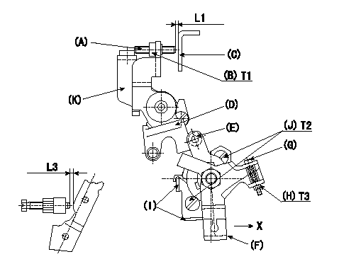
M-CSD adjustment
1. Fixing intermediate lever screw (A) [roller (E) must not contact intermediate lever (D)]
(1)Hold the control lever (C) in the idling position.
(2)At this time, adjust screw (A) so that it is horizontal and the clearance between screw (A) and the control lever (C) is L1. Then, fix using nut (B).
2. Fixing the M-CSD stopper (I)
Pull the CSD lever (F) in the direction X until it contacts the stopper (I) and tighten the socket head bolt (J) when the timer advance angle is L2.
3. Screw (G) adjustment
Pull the CSD lever (F) in the direction X until it contacts the stopper (I) and adjust the screw (G) so that the control lever shim thickness is L3. Then, tighten nut (H).
----------
L1=1~2(mm) L2=1.23+-0.2(mm) L3=7.2+-0.5(mm)
----------
T1=6~9(N-m)(0.6~0.9(kgf-m)) T2=5~7(N-m)(0.5~0.7(kgf-m)) T3=2~3(N-m)(0.2~0.3(kgf-m)) L1=1~2(mm) L3=7.2+-0.5(mm)
----------
L1=1~2(mm) L2=1.23+-0.2(mm) L3=7.2+-0.5(mm)
----------
T1=6~9(N-m)(0.6~0.9(kgf-m)) T2=5~7(N-m)(0.5~0.7(kgf-m)) T3=2~3(N-m)(0.2~0.3(kgf-m)) L1=1~2(mm) L3=7.2+-0.5(mm)
Information:
Solution
Caterpillar is aware of this problem and is recommending the following interim corrective action. Please follow the Special Instruction, M0110497, "Removal and Installation Procedure for DEF Heated Lines on Certain Machine Engines" for proper Disassembly and Assembly of the DEF heated lines to avoid failures. If a failure or DEF leak is noted even after following the special instructions, please use Service Magazine, M0103829, "Diesel Exhaust Fluid (DEF) Heated Lines May Be Damage on Certain Cat® Machines" for a temporary line repair. If additional help is needed, please go to the Parts Tech tab and enter a Product Health ticket in PSCRM.The new hose assemblies are listed in Table 1.
Table 1
Item Qty New Part Number Part Name
1 1 457-9011 Return Hose Assembly
2 1 457-9013 Return Hose Assembly
3 1 457-9026 Return Hose Assembly
4 1 457-9027 Return Hose Assembly
5 1 462-4206 Hose As
6 1 462-4210 Hose As
7 1 462-4211 Hose As
8 1 462-4219 Hose As
9 1 462-4220 Hose As
10 1 462-4221 Hose As
11 1 462-4223 Hose As
12 1 462-4224 Hose As
13 1 475-3231 Hose As
14 1 475-3232 Hose As
15 1 475-3233 Hose As
16 1 475-3234 Hose As
17 1 475-9989 Hose As
18 1 478-9071 Hose As
19 1 478-9072 Hose As
20 1 478-9074 Hose As
21 1 478-9075 Hose As
22 1 478-9077 Hose As
23 1 478-9078 Hose As
24 1 478-9079 Hose As
25 1 478-9081 Hose As
26 1 478-9082 Hose As
27 1 478-9083 Hose As
28 1 478-9085 Hose As
29 1 478-9086 Hose As
30 1 497-9305 Hose As
31 1 497-9306 Hose As
32 1 497-9307 Hose As
33 1 497-9308 Hose As
34 1 500-6215 Return Hose Assembly
35 1 500-6216 Return Hose Assembly
36 1 500-6217 Hose As
37 1 500-6218 Hose As
38 1 500-6219 Hose As
39 1 500-6220 Hose As
40 1 500-6221 Hose As
41 1 500-6222 Hose As
42 1 500-6223 Hose As
43 1 500-6224 Hose As
44 1 510-5191 Return Hose Assembly
45 1 510-5192 Hose As
46 1 510-5193 Hose As
47 1 510-5194 Hose As
48 1 552-3292 Hose As
49 1 552-3293 Hose As
50 1 552-3294 Hose As
51 1 552-3295 Hose As
52 1 579-9200 Hose As
53 1 579-9201 Hose As
54 1 579-9202 Hose As
55 1 579-9203 Hose As
Have questions with 104749-2441?
Group cross 104749-2441 ZEXEL
Nissan
Nitco(Misa)
Nissan
Nitco(Misa)
104749-2441
INJECTION-PUMP ASSEMBLY