Information injection-pump assembly
ZEXEL
104749-2213
1047492213
Rating:
Cross reference number
ZEXEL
104749-2213
1047492213
Zexel num
Bosch num
Firm num
Name
104749-2213
INJECTION-PUMP ASSEMBLY
Calibration Data:
Adjustment conditions
Test oil
1404 Test oil ISO4113orSAEJ967d
1404 Test oil ISO4113orSAEJ967d
Test oil temperature
degC
45
45
50
Nozzle
105000-2010
Bosch type code
NP-DN12SD12TT
Nozzle holder
105780-2080
Opening pressure
MPa
14.7
14.7
15.19
Opening pressure
kgf/cm2
150
150
155
Injection pipe
Inside diameter - outside diameter - length (mm) mm 2-6-840
Inside diameter - outside diameter - length (mm) mm 2-6-840
Transfer pump pressure
kPa
20
20
20
Transfer pump pressure
kgf/cm2
0.2
0.2
0.2
Direction of rotation (viewed from drive side)
Right R
Right R
Injection timing adjustment
Pump speed
r/min
900
900
900
Average injection quantity
mm3/st.
30.4
30
30.8
Difference in delivery
mm3/st.
2
Basic
*
Oil temperature
degC
50
48
52
Injection timing adjustment_02
Pump speed
r/min
600
600
600
Average injection quantity
mm3/st.
30.6
28.6
32.6
Oil temperature
degC
50
48
52
Injection timing adjustment_03
Pump speed
r/min
900
900
900
Average injection quantity
mm3/st.
30.4
29.4
31.4
Oil temperature
degC
50
48
52
Injection timing adjustment_04
Pump speed
r/min
1200
1200
1200
Average injection quantity
mm3/st.
31.8
29.8
33.8
Difference in delivery
mm3/st.
2.5
Basic
*
Oil temperature
degC
50
48
52
Injection timing adjustment_05
Pump speed
r/min
1800
1800
1800
Average injection quantity
mm3/st.
30.8
28.8
32.8
Oil temperature
degC
50
48
52
Injection timing adjustment_06
Pump speed
r/min
2300
2300
2300
Average injection quantity
mm3/st.
30.5
28.5
32.5
Oil temperature
degC
52
50
54
Injection timing adjustment_07
Pump speed
r/min
2500
2500
2500
Average injection quantity
mm3/st.
30.2
28.2
32.2
Oil temperature
degC
55
52
58
Injection quantity adjustment
Pump speed
r/min
2700
2700
2700
Average injection quantity
mm3/st.
14.5
12.5
16.5
Difference in delivery
mm3/st.
4.5
Basic
*
Oil temperature
degC
55
52
58
Injection quantity adjustment_02
Pump speed
r/min
2700
2700
2700
Average injection quantity
mm3/st.
14.5
11
18
Difference in delivery
mm3/st.
5
Basic
*
Oil temperature
degC
55
52
58
Injection quantity adjustment_03
Pump speed
r/min
2800
2800
2800
Average injection quantity
mm3/st.
6
Oil temperature
degC
55
52
58
Governor adjustment
Pump speed
r/min
350
350
350
Average injection quantity
mm3/st.
5.2
4.2
6.2
Difference in delivery
mm3/st.
2
Basic
*
Oil temperature
degC
48
46
50
Governor adjustment_02
Pump speed
r/min
350
350
350
Average injection quantity
mm3/st.
5.2
3.2
7.2
Difference in delivery
mm3/st.
2.5
Basic
*
Oil temperature
degC
48
46
50
Governor adjustment_03
Pump speed
r/min
500
500
500
Average injection quantity
mm3/st.
3
Oil temperature
degC
48
46
50
Boost compensator adjustment
Pump speed
r/min
600
600
600
Average injection quantity
mm3/st.
12.1
7.6
16.6
Oil temperature
degC
50
48
52
Lever angle (shim thickness)
mm
7.2
7.2
7.2
Boost compensator adjustment_02
Pump speed
r/min
900
900
900
Average injection quantity
mm3/st.
7
2
12
Oil temperature
degC
50
48
52
Lever angle (shim thickness)
mm
7.2
7.2
7.2
Timer adjustment
Pump speed
r/min
100
100
100
Average injection quantity
mm3/st.
50
40
60
Basic
*
Oil temperature
degC
48
46
50
Timer adjustment_02
Pump speed
r/min
100
100
100
Average injection quantity
mm3/st.
50
40
60
Oil temperature
degC
48
46
50
Speed control lever angle
Pump speed
r/min
350
350
350
Average injection quantity
mm3/st.
0
0
0
Oil temperature
degC
48
46
50
Remarks
Magnet OFF at idling position
Magnet OFF at idling position
Speed control lever angle_02
Pump speed
r/min
900
900
900
Average injection quantity
mm3/st.
0
0
0
Oil temperature
degC
50
48
52
Remarks
Magnet OFF at full-load position
Magnet OFF at full-load position
0000000901
Pump speed
r/min
900
900
900
Overflow quantity
cm3/min
330
200
460
Oil temperature
degC
50
48
52
Stop lever angle
Pump speed
r/min
900
900
900
Pressure
kPa
343
314
372
Pressure
kgf/cm2
3.5
3.2
3.8
Basic
*
Oil temperature
degC
50
48
52
Stop lever angle_02
Pump speed
r/min
900
900
900
Pressure
kPa
343
304
382
Pressure
kgf/cm2
3.5
3.1
3.9
Basic
*
Oil temperature
degC
50
48
52
Stop lever angle_03
Pump speed
r/min
1800
1800
1800
Pressure
kPa
539.5
500
579
Pressure
kgf/cm2
5.5
5.1
5.9
Oil temperature
degC
50
48
52
Stop lever angle_04
Pump speed
r/min
2300
2300
2300
Pressure
kPa
706
667
745
Pressure
kgf/cm2
7.2
6.8
7.6
Oil temperature
degC
52
50
54
0000001101
Pump speed
r/min
900
900
900
Timer stroke
mm
1.5
1.3
1.7
Basic
*
Oil temperature
degC
50
48
52
_02
Pump speed
r/min
900
900
900
Timer stroke
mm
1.5
1.2
1.8
Basic
*
Oil temperature
degC
50
48
52
_03
Pump speed
r/min
1200
1200
1200
Timer stroke
mm
3
2.7
3.3
Oil temperature
degC
50
48
52
_04
Pump speed
r/min
2300
2300
2300
Timer stroke
mm
8.4
7.8
9
Oil temperature
degC
52
50
54
0000001201
Max. applied voltage
V
8
8
8
Test voltage
V
13
12
14
Timing setting
K dimension
mm
3.3
3.2
3.4
KF dimension
mm
5.8
5.7
5.9
MS dimension
mm
1.2
1.1
1.3
Control lever angle alpha
deg.
25
21
29
Control lever angle beta
deg.
41
36
46
Test data Ex:
0000001801 M-CSD ADJUSTMENT
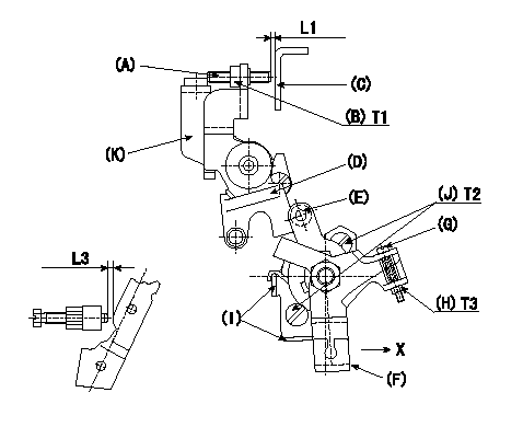
M-CSD adjustment
1. Fixing intermediate lever screw (A) [roller (E) must not contact intermediate lever (D)]
(1)Hold the control lever (C) in the idling position.
(2)At this time, adjust screw (A) so that it is horizontal and the clearance between screw (A) and the control lever (C) is L1. Then, fix using nut (B).
2. Fixing the M-CSD stopper (I)
Pull the CSD lever (F) in the direction X until it contacts the stopper (I) and tighten the socket head bolt (J) when the timer advance angle is L2.
3. Screw (G) adjustment
Pull the CSD lever (F) in the direction X until it contacts the stopper (I) and adjust the screw (G) so that the control lever shim thickness is L3. Then, tighten nut (H).
----------
L1=1~2mm L2=1.23+-0.2mm L3=7.2+-0.5mm
----------
T1=6~9N-m(0.6~0.9kgf-m) T2=5~7N-m(0.5~0.7kgf-m) T3=2~3N-m(0.2~0.3kgf-m) L1=1~2mm L3=7.2+-0.5mm
----------
L1=1~2mm L2=1.23+-0.2mm L3=7.2+-0.5mm
----------
T1=6~9N-m(0.6~0.9kgf-m) T2=5~7N-m(0.5~0.7kgf-m) T3=2~3N-m(0.2~0.3kgf-m) L1=1~2mm L3=7.2+-0.5mm
Information:
Literature Information
This manual should be stored in the operator's compartment in the literature holder or seat back literature storage area.This manual contains safety information, operation instructions, and maintenance recommendations.Some photographs or illustrations in this publication show details or attachments that can be different from your machine.Continuing improvement and advancement of product design might have caused changes to your machine which are not included in this publication. Read, study and keep this manual with the machine.Whenever a question arises regarding your machine, or this publication, please consult your Cat dealer for the latest available information.Safety
The safety section lists basic safety precautions. In addition, this section identifies the text and locations of warning signs and labels used on the machine.Operation
The operation section is a reference for the new operator and a refresher for the experienced operator. This section includes a discussion of gauges, switches, machine controls, attachment controls, and programming information.Photographs and illustrations guide the operator through correct procedures of checking, starting, operating and stopping the machine.Operating techniques outlined in this publication are basic. Skill and techniques develop as the operator gains knowledge of the machine and its capabilities.Maintenance
The maintenance section is a guide to equipment care.California Proposition 65 Warning
Diesel engine exhaust and some of its constituents are known to the State of California to cause cancer, birth defects, and other reproductive harm.Battery posts, terminals and related accessories contain lead and lead compounds.Wash hands after handlingCertified Engine Maintenance
Proper maintenance and repair is essential to keep the engine and machine systems operating correctly. As the heavy duty off-road diesel engine owner, you are responsible for the performance of the required maintenance listed in the Owner's Manual, Operation and Maintenance Manual, and Service Manual.It is prohibited for any person engaged in the business of repairing, servicing, selling, leasing, or trading engines or machines to remove, alter, or render inoperative any emission related device or element of design installed on or in an engine or machine that is in compliance with the regulations (40 CFR Part 89). Certain elements of the machine and engine such as the exhaust system, fuel system, electrical system, intake air system and cooling system may be emission related and should not be altered unless approved by Caterpillar.Cat Product Identification Number
Effective First Quarter 2001 the Cat Product Identification Number (PIN) will change from 8 to 17 characters. In an effort to provide uniform equipment identification, Caterpillar and other construction equipment manufacturers are moving to comply with the latest version of the product identification numbering standard. Non-road machine PINs are defined by ISO 10261. The new PIN format will apply to all Cat machines and generator sets. The PIN plates and frame marking will display the 17 character PIN. The new format will look like the following:
Illustration 1 g00751314Where:1. Caterpillar's World Manufacturing Code (characters 1-3)2. Machine Descriptor (characters 4-8)3. Check Character (character 9)4. Machine Indicator Section (MIS) or Product Sequence Number (characters 10-17). These were previously referred to as the Serial Number.Machines and generator sets produced before First Quarter 2001 will
Have questions with 104749-2213?
Group cross 104749-2213 ZEXEL
Nissan
Nissan
104749-2213
INJECTION-PUMP ASSEMBLY