Information injection-pump assembly
BOSCH
9 460 610 016
9460610016
ZEXEL
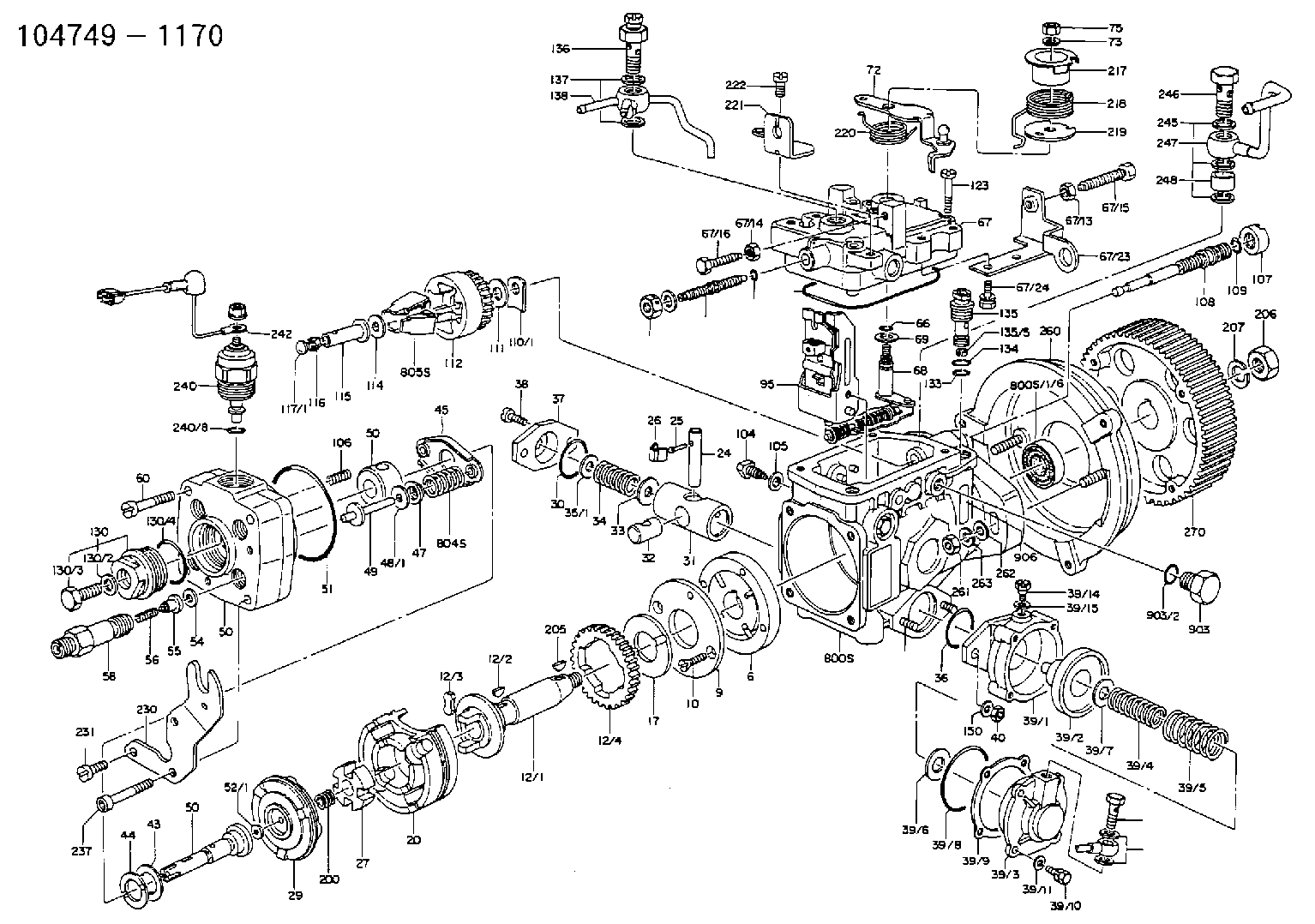
104749-1170
1047491170
ISUZU
5156010861
5156010861
Rating:
Components :
| 0. | INJECTION-PUMP ASSEMBLY | 104749-1170 |
| 1. | _ | |
| 2. | FUEL INJECTION PUMP | 104649-1170 |
| 3. | NUMBER PLATE | 146632-8000 |
| 4. | _ | |
| 5. | CAPSULE | 146620-0120 |
| 6. | ADJUSTING DEVICE | |
| 7. | NOZZLE AND HOLDER ASSY | 105151-1521 |
| 8. | Nozzle and Holder | 5-15300-109-1 |
| 9. | Open Pre:MPa(Kqf/cm2) | 10.3{105} |
| 10. | NOZZLE-HOLDER | 105081-3201 |
| 11. | NOZZLE | 105000-1740 |
Scheme ###:
| 1/6. | [1] | 146601-0700 | PACKING RING |
| 6. | [1] | 146100-0120 | SUPPLY PUMP |
| 9. | [1] | 146103-0000 | COVER |
| 10. | [2] | 139104-0000 | FLAT-HEAD SCREW |
| 12. | [1] | 146200-0320 | DRIVE SHAFT |
| 12/1. | [1] | 146200-0300 | DRIVE SHAFT |
| 12/2. | [1] | 146201-0000 | WOODRUFF KEY |
| 12/3. | [2] | 146202-0100 | DAMPER |
| 12/4. | [1] | 146203-0000 | TOOTHED GEAR |
| 17. | [1] | 146204-0000 | PLAIN WASHER |
| 20. | [1] | 146210-1720 | ROLLER SET |
| 24. | [1] | 146303-0000 | BEARING PIN |
| 25. | [1] | 146304-0000 | BEARING PIN |
| 26. | [1] | 146305-0000 | CLAMPING BAND |
| 27. | [1] | 146205-0000 | SLOTTED WASHER |
| 29. | [1] | 146220-0020 | CAM PLATE |
| 30. | [1] | 146600-0800 | O-RING |
| 31. | [1] | 146300-0900 | PUMP PLUNGER |
| 32. | [1] | 146301-0000 | SLIDING PIECE |
| 33. | [1] | 146603-0700 | SHIM D17.5&7.5T0.60 |
| 34. | [1] | 146302-3500 | COMPRESSION SPRING |
| 35/1. | [0] | 146603-0700 | SHIM D17.5&7.5T0.60 |
| 35/1. | [0] | 146603-0800 | SHIM D17.5&7.5T0.70 |
| 35/1. | [0] | 146603-0900 | SHIM D17.5&7.5T0.90 |
| 35/1. | [0] | 146603-1000 | SHIM D17.5&7.5T1.00 |
| 35/1. | [0] | 146603-1100 | SHIM D17.5&7.5T1.20 |
| 35/1. | [0] | 146603-3600 | SHIM D17.5&7.5T2.40 |
| 36. | [1] | 146600-0800 | O-RING |
| 37. | [1] | 146310-0000 | COVER |
| 38. | [2] | 146620-5000 | BLEEDER SCREW |
| 39. | [1] | 146340-0620 | START ADVANCE ASSY |
| 39/1. | [1] | 146342-1900 | DIAPHRAGM HOUSING |
| 39/2. | [1] | 146342-1220 | PUMP PLUNGER |
| 39/3. | [1] | 146342-1300 | COVER |
| 39/4. | [1] | 146342-1600 | COILED SPRING |
| 39/5. | [1] | 146342-1700 | COILED SPRING |
| 39/6. | [1] | 146342-0600 | PLAIN WASHER |
| 39/7/1. | [0] | 146603-0700 | SHIM D17.5&7.5T0.60 |
| 39/7/1. | [0] | 146603-0800 | SHIM D17.5&7.5T0.70 |
| 39/7/1. | [0] | 146603-0900 | SHIM D17.5&7.5T0.90 |
| 39/7/1. | [0] | 146603-1000 | SHIM D17.5&7.5T1.00 |
| 39/7/1. | [0] | 146603-1100 | SHIM D17.5&7.5T1.20 |
| 39/7/1. | [0] | 146603-3600 | SHIM D17.5&7.5T2.40 |
| 39/8. | [1] | 146342-0700 | O-RING |
| 39/9. | [1] | 146342-1400 | GASKET |
| 39/10. | [4] | 010065-1670 | BLEEDER SCREW M5P0.8L16 7T |
| 39/11. | [4] | 014020-5140 | PLAIN WASHER D10&5.5T0.8 |
| 39/14. | [1] | 131420-0400 | BLEEDER SCREW |
| 39/15. | [1] | 026506-1040 | GASKET D9.9&6.2T1 |
| 40. | [2] | 013020-6040 | UNION NUT M6P1H5 |
| 43. | [1] | 146230-0000 | SHIM |
| 44. | [1] | 146230-0100 | PLAIN WASHER |
| 45. | [1] | 146231-0001 | SLOTTED WASHER |
| 47. | [2] | 146233-0000 | SLOTTED WASHER |
| 48/1. | [1] | 146603-0000 | SHIM D17.0&5.2T0.50 |
| 48/1. | [1] | 146603-0100 | SHIM D17.0&5.2T0.80 |
| 48/1. | [1] | 146603-0200 | SHIM D17.0&5.2T1.00 |
| 48/1. | [1] | 146603-0300 | SHIM D17.0&5.2T1.20 |
| 48/1. | [1] | 146603-0400 | SHIM D17.0&5.2T1.50 |
| 48/1. | [1] | 146603-0500 | SHIM D17.0&5.2T1.80 |
| 48/1. | [1] | 146603-0600 | SHIM D17.0&5.2T2.00 |
| 48/1. | [1] | 146690-1400 | SHIM D17&5.2T0.9 |
| 48/1. | [1] | 146690-1500 | SHIM D17&5.2T1.1 |
| 48/1. | [1] | 146690-1600 | SHIM D17&5.2T1.3 |
| 48/1. | [1] | 146690-1700 | SHIM D17&5.2T1.4 |
| 48/1. | [1] | 146690-1800 | SHIM D17&5.2T1.6 |
| 48/1. | [1] | 146690-1900 | SHIM D17&5.2T1.7 |
| 48/1. | [1] | 146690-5800 | SHIM D17&5.2T2.1 |
| 48/1. | [1] | 146690-5900 | SHIM D17&5.2T2.2 |
| 48/1. | [1] | 146690-6000 | SHIM D17&5.2T2.3 |
| 48/1. | [1] | 146690-6100 | SHIM D17&5.2T2.4 |
| 48/1. | [1] | 146690-6200 | SHIM D17&5.2T2.5 |
| 48/1. | [1] | 146690-6300 | SHIM D17&5.2T2.6 |
| 48/1. | [1] | 146690-6400 | SHIM D17&5.2T2.7 |
| 48/1. | [1] | 146690-6500 | SHIM D17&5.2T2.8 |
| 48/1. | [1] | 146690-6600 | SHIM D17&5.2T2.9 |
| 48/1. | [1] | 146690-6700 | SHIM D17&5.2T3.0 |
| 48/1. | [1] | 146690-6800 | SHIM D17&5.2T3.1 |
| 48/1. | [1] | 146690-6900 | SHIM D17&5.2T3.2 |
| 48/1. | [1] | 146690-7000 | SHIM D17&5.2T3.3 |
| 48/1. | [1] | 146690-7100 | SHIM D17&5.2T3.4 |
| 48/1. | [1] | 146690-7200 | SHIM D17&5.2T0.4 |
| 48/1. | [1] | 146690-7300 | SHIM D17&5.2T0.6 |
| 48/1. | [1] | 146690-7400 | SHIM D17&5.2T0.7 |
| 48/1. | [1] | 146690-7500 | SHIM D17&5.2T1.9 |
| 48/1. | [1] | 146690-7800 | SHIM D17&5.2T0.2 |
| 49. | [2] | 146234-0500 | GUIDE PIN |
| 50. | [1] | 146400-5220 | HYDRAULIC HEAD |
| 50. | [1] | 146400-5220 | HYDRAULIC HEAD |
| 50. | [1] | 146400-5220 | HYDRAULIC HEAD |
| 51. | [1] | 146600-0000 | O-RING |
| 52/1. | [1] | 146420-0000 | SHIM D9.5&3.0T1.90 |
| 52/1. | [1] | 146420-0100 | SHIM D9.5&3.0T1.92 |
| 52/1. | [1] | 146420-0200 | SHIM D9.5&3.0T1.94 |
| 52/1. | [1] | 146420-0300 | SHIM D9.5&3.0T1.96 |
| 52/1. | [1] | 146420-0400 | SHIM D9.5&3.0T1.98 |
| 52/1. | [1] | 146420-0500 | SHIM D9.5&3.0T2.00 |
| 52/1. | [1] | 146420-0600 | SHIM D9.5&3.0T2.02 |
| 52/1. | [1] | 146420-0700 | SHIM D9.5&3.0T2.04 |
| 52/1. | [1] | 146420-0800 | SHIM D9.5&3.0T2.06 |
| 52/1. | [1] | 146420-0900 | SHIM D9.5&3.0T2.08 |
| 52/1. | [1] | 146420-1000 | SHIM D9.5&3.0T2.10 |
| 52/1. | [1] | 146420-1100 | SHIM D9.5&3.0T2.12 |
| 52/1. | [1] | 146420-1200 | SHIM D9.5&3.0T2.14 |
| 52/1. | [1] | 146420-1300 | SHIM D9.5&3.0T2.16 |
| 52/1. | [1] | 146420-1400 | SHIM D9.5&3.0T2.18 |
| 52/1. | [1] | 146420-1500 | SHIM D9.5&3.0T2.20 |
| 52/1. | [1] | 146420-1600 | SHIM D9.5&3.0T2.22 |
| 52/1. | [1] | 146420-1700 | SHIM D9.5&3.0T2.24 |
| 52/1. | [1] | 146420-1800 | SHIM D9.5&3.0T2.26 |
| 52/1. | [1] | 146420-1900 | SHIM D9.5&3.0T2.28 |
| 52/1. | [1] | 146420-2000 | SHIM D9.5&3.0T2.30 |
| 52/1. | [1] | 146420-2100 | SHIM D9.5&3.0T2.32 |
| 52/1. | [1] | 146420-2200 | SHIM D9.5&3.0T2.34 |
| 52/1. | [1] | 146420-2300 | SHIM D9.5&3.0T2.36 |
| 52/1. | [1] | 146420-2400 | SHIM D9.5&3.0T2.38 |
| 52/1. | [1] | 146420-2500 | SHIM D9.5&3.0T2.40 |
| 52/1. | [1] | 146420-2600 | SHIM D9.5&3.0T2.42 |
| 52/1. | [1] | 146420-2700 | SHIM D9.5&3.0T2.44 |
| 52/1. | [1] | 146420-2800 | SHIM D9.5&3.0T2.46 |
| 52/1. | [1] | 146420-2900 | SHIM D9.5&3.0T2.48 |
| 52/1. | [1] | 146420-3000 | SHIM D9.5&3.0T2.50 |
| 52/1. | [1] | 146420-3100 | SHIM D9.5&3.0T2.52 |
| 52/1. | [1] | 146420-3200 | SHIM D9.5&3.0T2.54 |
| 52/1. | [1] | 146420-3300 | SHIM D9.5&3.0T2.56 |
| 52/1. | [1] | 146420-3400 | SHIM D9.5&3.0T2.58 |
| 52/1. | [1] | 146420-3500 | SHIM D9.5&3.0T2.60 |
| 52/1. | [1] | 146420-3600 | SHIM D9.5&3.0T2.62 |
| 52/1. | [1] | 146420-3700 | SHIM D9.5&3.0T2.64 |
| 52/1. | [1] | 146420-3800 | SHIM D9.5&3.0T2.66 |
| 52/1. | [1] | 146420-3900 | SHIM D9.5&3.0T2.68 |
| 52/1. | [1] | 146420-4000 | SHIM D9.5&3.0T2.70 |
| 52/1. | [1] | 146420-4100 | SHIM D9.5&3.0T2.72 |
| 52/1. | [1] | 146420-4200 | SHIM D9.5&3.0T2.74 |
| 52/1. | [1] | 146420-4300 | SHIM D9.5&3.0T2.76 |
| 52/1. | [1] | 146420-4400 | SHIM D9.5&3.0T2.78 |
| 52/1. | [1] | 146420-4500 | SHIM D9.5&3.0T2.80 |
| 52/1. | [1] | 146420-4600 | SHIM D9.5&3.0T2.82 |
| 52/1. | [1] | 146420-4700 | SHIM D9.5&3.0T2.84 |
| 52/1. | [1] | 146420-4800 | SHIM D9.5&3.0T2.86 |
| 52/1. | [1] | 146420-4900 | SHIM D9.5&3.0T2.88 |
| 52/1. | [1] | 146420-5000 | SHIM D9.5&3.0T2.90 |
| 52/1. | [1] | 146420-5100 | SHIM D9.5&3.0T1.74 |
| 52/1. | [1] | 146420-5200 | SHIM D9.5&3.0T1.76 |
| 52/1. | [1] | 146420-5300 | SHIM D9.5&3.0T1.78 |
| 52/1. | [1] | 146420-5400 | SHIM D9.5&3.0T1.80 |
| 52/1. | [1] | 146420-5500 | SHIM D9.5&3.0T1.82 |
| 52/1. | [1] | 146420-5600 | SHIM D9.5&3.0T1.84 |
| 52/1. | [1] | 146420-5700 | SHIM D9.5&3.0T1.86 |
| 52/1. | [1] | 146420-5800 | SHIM D9.5&3.0T1.88 |
| 54. | [4] | 146433-0100 | GASKET D12&6.4T1.00 |
| 55. | [4] | 146430-0020 | DELIVERY-VALVE ASSEMBLY |
| 56. | [4] | 146432-0000 | COMPRESSION SPRING |
| 58. | [4] | 146440-0120 | FITTING |
| 60. | [3] | 139106-0100 | FLAT-HEAD SCREW |
| 66. | [1] | 146600-0100 | O-RING |
| 67. | [1] | 146502-4620 | GOVERNOR COVER |
| 67/1. | [1] | 146505-2421 | GOVERNOR COVER |
| 67/13. | [1] | 013020-6040 | UNION NUT M6P1H5 |
| 67/14. | [1] | 029240-6010 | UNION NUT M6P1.0H5* |
| 67/15. | [1] | 146526-1800 | BLEEDER SCREW |
| 67/16. | [1] | 146526-0200 | BLEEDER SCREW |
| 67/23. | [1] | 146613-8000 | BRACKET |
| 67/24. | [2] | 020106-1640 | BLEEDER SCREW M6P1.0L14 |
| 67/26. | [1] | 146613-6520 | BRACKET |
| 67/78. | [1] | 146600-4400 | SEAL RING |
| 67/78. | [1] | 146600-4400 | SEAL RING |
| 67/78. | [1] | 146600-4400 | SEAL RING |
| 67/200. | [1] | 139308-0300 | PLAIN WASHER |
| 67/201. | [1] | 146545-3400 | THREADED PIN L53.00 |
| 67/201B. | [1] | 146545-3500 | THREADED PIN L55.00 |
| 67/201C. | [1] | 146545-3600 | THREADED PIN L57.00 |
| 67/202. | [1] | 139208-0900 | UNION NUT |
| 67/203. | [1] | 146600-1200 | O-RING |
| 68. | [1] | 146510-0220 | CONTROL SHAFT |
| 69. | [1] | 139310-0200 | PLAIN WASHER |
| 72. | [1] | 146530-7920 | CONTROL LEVER |
| 72B. | [1] | 146530-8020 | CONTROL LEVER |
| 73. | [1] | 014110-6440 | LOCKING WASHER |
| 75. | [1] | 013020-6040 | UNION NUT M6P1H5 |
| 95. | [1] | 146551-1020 | FULCRUM LEVER |
| 104. | [2] | 146568-0000 | SLOTTED SPRING PIN |
| 105. | [2] | 026508-1140 | GASKET D11.4&8.2T1 |
| 106. | [2] | 146588-0500 | COILED SPRING |
| 107. | [1] | 146569-0300 | UNION NUT |
| 108. | [1] | 146570-0100 | GOVERNOR SHAFT |
| 109. | [1] | 146600-0400 | O-RING |
| 110/1. | [1] | 146571-0000 | SHIM D20.2&8.3T1.05 |
| 110/1. | [1] | 146571-0100 | SHIM D20.2&8.3T1.25 |
| 110/1. | [1] | 146571-0200 | SHIM D20.2&8.3T1.45 |
| 110/1. | [1] | 146571-0300 | SHIM D20.2&8.3T1.65 |
| 110/1. | [1] | 146571-0400 | SHIM D20.2&8.3T1.85 |
| 110/1. | [1] | 146571-0500 | SHIM D20.2&8.3T1.15 |
| 110/1. | [1] | 146571-0600 | SHIM D20.2&8.3T1.35 |
| 110/1. | [1] | 146571-0700 | SHIM D20.2&8.3T1.55 |
| 110/1. | [1] | 146571-0800 | SHIM D20.2&8.3T1.75 |
| 111. | [1] | 146602-0600 | PLAIN WASHER D20&8.4T1.40 |
| 112. | [1] | 146572-0020 | FLYWEIGHT ASSEMBLY |
| 114. | [1] | 146602-0500 | PLAIN WASHER D17&6.4T1.60 |
| 115. | [1] | 146575-0000 | SLIDING SLEEVE |
| 116. | [1] | 146576-0000 | SEALING CAP |
| 117/1. | [1] | 146577-0000 | PLUG L1.70 |
| 117/1. | [1] | 146577-0100 | PLUG L1.90 |
| 117/1. | [1] | 146577-0200 | PLUG L2.10 |
| 117/1. | [1] | 146577-0300 | PLUG L2.30 |
| 117/1. | [1] | 146577-0400 | PLUG L2.50 |
| 117/1. | [1] | 146577-0500 | PLUG L2.70 |
| 117/1. | [1] | 146577-0600 | PLUG L2.90 |
| 117/1. | [1] | 146577-0700 | PLUG L3.10 |
| 117/1. | [1] | 146577-0800 | PLUG L3.30 |
| 117/1. | [1] | 146577-0900 | PLUG L3.50 |
| 117/1. | [1] | 146577-1000 | PLUG L3.70 |
| 117/1. | [1] | 146577-1100 | PLUG L3.90 |
| 117/1. | [1] | 146577-1200 | PLUG L4.10 |
| 117/1. | [1] | 146577-1300 | PLUG L4.30 |
| 117/1. | [1] | 146577-1400 | PLUG L4.50 |
| 117/1. | [1] | 146577-1500 | PLUG L4.70 |
| 117/1. | [1] | 146577-1600 | PLUG L4.90 |
| 117/1. | [1] | 146577-1700 | PLUG L5.10 |
| 117/1. | [1] | 146577-5000 | PLUG L1.8 |
| 117/1. | [1] | 146577-5100 | PLUG L2.0 |
| 117/1. | [1] | 146577-5200 | PLUG L2.2 |
| 117/1. | [1] | 146577-5300 | PLUG L2.4 |
| 117/1. | [1] | 146577-5400 | PLUG L2.6 |
| 117/1. | [1] | 146577-5500 | PLUG L2.8 |
| 117/1. | [1] | 146577-5600 | PLUG L3.0 |
| 117/1. | [1] | 146577-5700 | PLUG L3.2 |
| 117/1. | [1] | 146577-5800 | PLUG L3.4 |
| 117/1. | [1] | 146577-5900 | PLUG L3.6 |
| 117/1. | [1] | 146577-6000 | PLUG L3.8 |
| 117/1. | [1] | 146577-6100 | PLUG L4.0 |
| 117/1. | [1] | 146577-6200 | PLUG L4.2 |
| 117/1. | [1] | 146577-6300 | PLUG L4.4 |
| 117/1. | [1] | 146577-6400 | PLUG L4.6 |
| 117/1. | [1] | 146577-6500 | PLUG L4.8 |
| 117/1. | [1] | 146577-6600 | PLUG L5.0 |
| 117/1. | [1] | 146877-0400 | PLUG |
| 117/1. | [1] | 146877-0500 | PLUG |
| 117/1. | [1] | 146877-0600 | PLUG |
| 117/1. | [1] | 146877-0700 | PLUG |
| 117/1. | [1] | 146877-4300 | PLUG |
| 117/1. | [1] | 146877-4400 | PLUG |
| 117/1. | [1] | 146877-4500 | PLUG |
| 117/1. | [1] | 146877-4600 | PLUG |
| 123. | [4] | 139106-0200 | FLAT-HEAD SCREW |
| 130. | [1] | 146421-0020 | CAPSULE |
| 130/2. | [1] | 026508-1140 | GASKET D11.4&8.2T1 |
| 130/3. | [1] | 146422-0000 | BLEEDER SCREW |
| 130/4. | [1] | 146600-0500 | O-RING |
| 133. | [1] | 146600-0600 | O-RING |
| 134. | [1] | 146600-0700 | O-RING |
| 135. | [1] | 146110-0220 | CONTROL VALVE |
| 135/5. | [1] | 146114-0000 | SPRING WASHER |
| 136. | [1] | 146120-0020 | OVER FLOW VALVE |
| 137. | [2] | 139512-0500 | GASKET |
| 138. | [1] | 146609-1120 | PIPE |
| 150. | [2] | 014020-6140 | PLAIN WASHER |
| 151. | [2] | 139010-0300 | STUD |
| 153. | [1] | 029730-6030 | EYE BOLT |
| 154. | [2] | 026506-1040 | GASKET D9.9&6.2T1 |
| 200. | [1] | 146206-0100 | COILED SPRING |
| 205. | [1] | 025804-1610 | WOODRUFF KEY |
| 206. | [1] | 013121-4140 | UNION NUT M14P1.5H11 |
| 207. | [1] | 029321-4050 | LOCKING WASHER |
| 217. | [1] | 146541-0100 | SLOTTED WASHER |
| 218. | [1] | 146587-0800 | COILED SPRING |
| 219. | [1] | 146541-0200 | ANGLE PIECE |
| 220. | [1] | 146587-0900 | COILED SPRING |
| 221. | [1] | 146613-6500 | BRACKET |
| 222. | [1] | 139106-0400 | FLAT-HEAD SCREW M6P1.0H12 |
| 230. | [1] | 146613-7400 | BRACKET |
| 231. | [2] | 139106-0500 | FLAT-HEAD SCREW M6P1.0H25 |
| 237. | [1] | 146620-0200 | HEX-SOCKET-HEAD CAP SCREW |
| 240. | [1] | 146650-1220 | PULLING ELECTROMAGNET |
| 240/8. | [1] | 146600-1700 | O-RING |
| 240/8. | [1] | 146600-1700 | O-RING |
| 242. | [1] | 146658-7320 | WIRE |
| 243. | [1] | 146621-1000 | UNION NUT |
| 245. | [3] | 139512-0500 | GASKET |
| 246. | [1] | 146125-0020 | EYE BOLT |
| 247. | [1] | 146610-8120 | INLET UNION |
| 248. | [1] | 146614-0200 | SPACER BUSHING |
| 260. | [1] | 146611-0021 | BRACKET |
| 261. | [2] | 146621-4700 | UNION NUT |
| 270. | [1] | 146615-0000 | TIMER CORE |
| 800S. | [1] | 146009-1020 | PUMP HOUSING |
| 800S/1/6. | [1] | 146601-0700 | PACKING RING |
| 800S/1/6. | [1] | 146601-0700 | PACKING RING |
| 804S. | [1] | 146232-0220 | COMPRESSION SPRING |
| 805S. | [1] | 146574-0120 | PARTS SET |
| 810S. | [1] | 146600-1120 | REPAIR SET |
| 811S. | [1] | 146600-1820 | PARTS SET |
| 821S. | [1] | 146210-5720 | ROLLER SET |
| 903. | [1] | 146620-0120 | CAPSULE |
| 903/2. | [1] | 146600-1300 | O-RING &13W1.9 |
| 906. | [1] | 146632-8000 | NAMEPLATE |
Include in #2:
104749-1170
as INJECTION-PUMP ASSEMBLY
Cross reference number
BOSCH
9 460 610 016
9460610016
ZEXEL
104749-1170
1047491170
ISUZU
5156010861
5156010861
Zexel num
Bosch num
Firm num
Name
Calibration Data:
Adjustment conditions
Test oil
1404 Test oil ISO4113orSAEJ967d
1404 Test oil ISO4113orSAEJ967d
Test oil temperature
degC
45
45
50
Nozzle
105000-2010
Bosch type code
NP-DN12SD12TT
Nozzle holder
105780-2080
Opening pressure
MPa
14.7
14.7
15.19
Opening pressure
kgf/cm2
150
150
155
Injection pipe
Inside diameter - outside diameter - length (mm) mm 2-6-840
Inside diameter - outside diameter - length (mm) mm 2-6-840
Transfer pump pressure
kPa
20
20
20
Transfer pump pressure
kgf/cm2
0.2
0.2
0.2
Direction of rotation (viewed from drive side)
Right R
Right R
Injection timing adjustment
Pump speed
r/min
1500
1500
1500
Average injection quantity
mm3/st.
41.6
41.1
42.1
Difference in delivery
mm3/st.
3
Basic
*
Injection timing adjustment_02
Pump speed
r/min
2440
2440
2440
Average injection quantity
mm3/st.
13.7
10.7
16.7
Injection timing adjustment_03
Pump speed
r/min
2175
2175
2175
Average injection quantity
mm3/st.
37.6
35.6
39.6
Injection timing adjustment_04
Pump speed
r/min
1500
1500
1500
Average injection quantity
mm3/st.
41.6
40.6
42.6
Injection timing adjustment_05
Pump speed
r/min
600
600
600
Average injection quantity
mm3/st.
32.8
30.8
34.8
Injection timing adjustment_06
Pump speed
r/min
1500
1500
1500
Average injection quantity
mm3/st.
40.6
40.1
41.1
Difference in delivery
mm3/st.
3
Basic
*
Remarks
For Japan
For Japan
Injection timing adjustment_07
Pump speed
r/min
2440
2440
2440
Average injection quantity
mm3/st.
13.4
10.4
16.4
Remarks
For Japan
For Japan
Injection timing adjustment_08
Pump speed
r/min
2175
2175
2175
Average injection quantity
mm3/st.
36.7
34.7
38.7
Remarks
For Japan
For Japan
Injection timing adjustment_09
Pump speed
r/min
1500
1500
1500
Average injection quantity
mm3/st.
40.6
39.6
41.6
Remarks
For Japan
For Japan
Injection timing adjustment_10
Pump speed
r/min
600
600
600
Average injection quantity
mm3/st.
32
30
34
Remarks
For Japan
For Japan
Injection quantity adjustment
Pump speed
r/min
2440
2440
2440
Average injection quantity
mm3/st.
13.7
10.7
16.7
Basic
*
Injection quantity adjustment_02
Pump speed
r/min
2550
2550
2550
Average injection quantity
mm3/st.
6.2
Injection quantity adjustment_03
Pump speed
r/min
2440
2440
2440
Average injection quantity
mm3/st.
13.4
10.4
16.4
Basic
*
Remarks
For Japan
For Japan
Injection quantity adjustment_04
Pump speed
r/min
2550
2550
2550
Average injection quantity
mm3/st.
6
Remarks
For Japan
For Japan
Governor adjustment
Pump speed
r/min
350
350
350
Average injection quantity
mm3/st.
7.7
5.7
9.7
Difference in delivery
mm3/st.
2
Basic
*
Governor adjustment_02
Pump speed
r/min
350
350
350
Average injection quantity
mm3/st.
7.7
5.7
9.7
Governor adjustment_03
Pump speed
r/min
450
450
450
Average injection quantity
mm3/st.
3.1
Governor adjustment_04
Pump speed
r/min
350
350
350
Average injection quantity
mm3/st.
7.5
5.5
9.5
Difference in delivery
mm3/st.
2
Basic
*
Remarks
For Japan
For Japan
Governor adjustment_05
Pump speed
r/min
350
350
350
Average injection quantity
mm3/st.
7.5
5.5
9.5
Remarks
For Japan
For Japan
Governor adjustment_06
Pump speed
r/min
450
450
450
Average injection quantity
mm3/st.
3
Remarks
For Japan
For Japan
Timer adjustment
Pump speed
r/min
100
100
100
Average injection quantity
mm3/st.
65
65
Basic
*
Timer adjustment_02
Pump speed
r/min
100
100
100
Average injection quantity
mm3/st.
63
63
Basic
*
Remarks
For Japan
For Japan
Speed control lever angle
Pump speed
r/min
350
350
350
Average injection quantity
mm3/st.
0
0
0
Remarks
Magnet OFF
Magnet OFF
Speed control lever angle_02
Pump speed
r/min
350
350
350
Average injection quantity
mm3/st.
0
0
0
Remarks
For Japan: Magnet OFF
For Japan: Magnet OFF
0000000901
Pump speed
r/min
1000
1000
1000
Overflow quantity
cm3/min
417
288
546
_02
Pump speed
r/min
1000
1000
1000
Overflow quantity
cm3/min
441
312
570
Remarks
For Japan
For Japan
Stop lever angle
Pump speed
r/min
1500
1500
1500
Pressure
kPa
539.5
520
559
Pressure
kgf/cm2
5.5
5.3
5.7
Basic
*
Stop lever angle_02
Pump speed
r/min
1000
1000
1000
Pressure
kPa
411.5
382
441
Pressure
kgf/cm2
4.2
3.9
4.5
Stop lever angle_03
Pump speed
r/min
1500
1500
1500
Pressure
kPa
539.5
520
559
Pressure
kgf/cm2
5.5
5.3
5.7
Stop lever angle_04
Pump speed
r/min
2175
2175
2175
Pressure
kPa
696.5
667
726
Pressure
kgf/cm2
7.1
6.8
7.4
Stop lever angle_05
Pump speed
r/min
1500
1500
1500
Pressure
kPa
529.5
510
549
Pressure
kgf/cm2
5.4
5.2
5.6
Basic
*
Remarks
For Japan
For Japan
Stop lever angle_06
Pump speed
r/min
1000
1000
1000
Pressure
kPa
402
373
431
Pressure
kgf/cm2
4.1
3.8
4.4
Remarks
For Japan
For Japan
Stop lever angle_07
Pump speed
r/min
1500
1500
1500
Pressure
kPa
529.5
510
549
Pressure
kgf/cm2
5.4
5.2
5.6
Remarks
For Japan
For Japan
Stop lever angle_08
Pump speed
r/min
2175
2175
2175
Pressure
kPa
676.5
647
706
Pressure
kgf/cm2
6.9
6.6
7.2
Remarks
For Japan
For Japan
0000001101
Pump speed
r/min
1500
1500
1500
Timer stroke
mm
4.5
4.3
4.7
Basic
*
_02
Pump speed
r/min
1000
1000
1000
Timer stroke
mm
2.3
1.7
2.9
_03
Pump speed
r/min
1500
1500
1500
Timer stroke
mm
4.5
4.2
4.8
_04
Pump speed
r/min
2175
2175
2175
Timer stroke
mm
7.4
7
7.8
_05
Pump speed
r/min
560
460
660
Remarks
C.D.. cancel speed.
C.D.. cancel speed.
_06
Pump speed
r/min
0
0
0
Timer stroke
mm
2.9
2.7
3.1
_07
Pump speed
r/min
560
460
660
Remarks
C.D.. cancel speed.
C.D.. cancel speed.
_08
Pump speed
r/min
1500
1500
1500
Timer stroke
mm
4.4
4.2
4.6
Basic
*
Remarks
For Japan
For Japan
_09
Pump speed
r/min
1000
1000
1000
Timer stroke
mm
2.2
1.6
2.8
Remarks
For Japan
For Japan
_10
Pump speed
r/min
1500
1500
1500
Timer stroke
mm
4.4
4.1
4.7
Remarks
For Japan
For Japan
_11
Pump speed
r/min
2175
2175
2175
Timer stroke
mm
7.35
6.9
7.8
Remarks
For Japan
For Japan
_12
Pump speed
r/min
600
500
700
Remarks
For Japan: CSD cancel speed
For Japan: CSD cancel speed
_13
Pump speed
r/min
0
0
0
Timer stroke
mm
2.9
2.7
3.1
Remarks
For Japan
For Japan
_14
Pump speed
r/min
600
500
700
Remarks
For Japan: CSD cancel speed
For Japan: CSD cancel speed
0000001201
Max. applied voltage
V
8
8
8
Test voltage
V
13
12
14
Timing setting
K dimension
mm
3.3
3.2
3.4
KF dimension
mm
5.8
5.7
5.9
MS dimension
mm
1.8
1.7
1.9
Control lever angle alpha
deg.
25
21
29
Control lever angle beta
deg.
41.5
36.5
46.5
Information:
Indicator Readings
If, the indicator reading a positive (+), the tip of the indicator moved into the indicator and minus (-) means that the tip of the indicator moved out of the dial indicator.When comparing two positive (+) indicator readings, the larger numerical reading is more than the smaller numerical reading. However, when comparing two minus (-) indicator readings, the larger numerical reading is less than the smaller numerical reading. In both cases, the indicator reading becomes less as the tip of the indicator moves out of the dial indicator.The Total Indicator Reading (TIR) is the total amount of movement of the indicator needle. The TIR is always a positive value even though one or both of the readings are negative. For example: If the indicator reading varied from -10 to +5, the TIR was 15. If the indicator reading is varied from -5 to - 15, the TIR was 10.Laser Tool Alignment Procedure
Note: Refer to the laser alignment tool user manual instructions for additional information regarding operation of the tool.To do laser tool alignment, perform the following steps:
Mount the transducer to the outer coupling element.
Attach the reflector to the generator hub.
Enter the required dimensions into the laser alignment tool. Examples of possible dimensions required include the following:
Transducer to reflector
Transducer to coupling centerline
Coupling diameter
Rotations Per Minute (RPM)
Transducer to front feet
Front feet to rear feet
Turn the laser ON, adjust the laser beam to the center of the reflector dust cap. Once the laser beam is centered, remove the dust cap.
Rotate the drive line one complete revolution.
Record the results displayed on the laser alignment tool. Compare the readings to the acceptable values listed in the "Generator Set Alignment Data Sheet".
Adjust the generator as needed to obtain the correct alignment. Shims may be installed or removed to achieve the correct vertical alignment. Use the horizontal adjustment screws to make horizontal adjustments.
Once the alignment is within the specifications, torque the generator mounting bolts to the proper specifications.
Perform a soft foot check. Refer to "Soft Foot Check Procedure".Soft Foot Check Procedure
Note: The soft foot check can be completed with the laser alignment tool if the tool has this function.
Ensure that all jacking screws are loose
Mount a dial indicator from the base assembly to the top of the generator mounting foot to be measured.
Preload the dial indicator to a minimum of one revolution or 2 mm (0.08 inch). Once the correct preload is set, zero the dial indicator.
Loosen the mounting bolt at the location that is being measured. Measure and record the vertical deflection of the generator mounting foot at this location as close to the mounting bolt as possible. Only loosen one bolt at a time.
The maximum deflection of the mounting foot is 0.076 mm (0.003 inch). If the indicator reading is greater than this amount, add shims to eliminate the soft foot condition. Torque the mounting bolt before moving to the next mounting foot to be measured for soft foot.
Repeat the procedure on the remaining generator mounting feet.
Perform the final torque of the