Information injection-pump assembly
BOSCH
9 460 610 015
9460610015
ZEXEL
104749-1020
1047491020
ISUZU
5156010700
5156010700

Rating:
Components :
| 0. | INJECTION-PUMP ASSEMBLY | 104749-1020 |
| 1. | _ | |
| 2. | FUEL INJECTION PUMP | 104649-1080 |
| 3. | NUMBER PLATE | 146632-1200 |
| 4. | _ | |
| 5. | CAPSULE | 146620-0120 |
| 6. | ADJUSTING DEVICE | |
| 7. | NOZZLE AND HOLDER ASSY | 105151-1521 |
| 8. | Nozzle and Holder | 5-15300-109-1 |
| 9. | Open Pre:MPa(Kqf/cm2) | 10.3{105} |
| 10. | NOZZLE-HOLDER | 105081-3201 |
| 11. | NOZZLE | 105000-1740 |
Scheme ###:
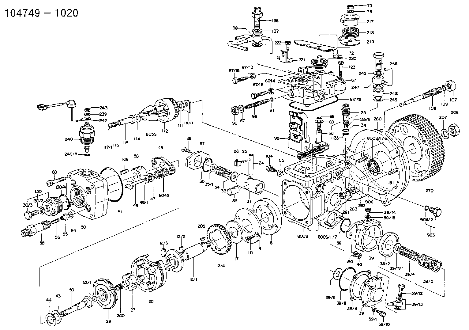
| 1/6. | [1] | 146601-0700 | PACKING RING |
| 6. | [1] | 146100-0120 | SUPPLY PUMP |
| 9. | [1] | 146103-0000 | COVER |
| 10. | [2] | 139104-0000 | FLAT-HEAD SCREW |
| 12. | [1] | 146200-0320 | DRIVE SHAFT |
| 12/1. | [1] | 146200-0300 | DRIVE SHAFT |
| 12/2. | [1] | 146201-0000 | WOODRUFF KEY |
| 12/3. | [2] | 146202-0100 | DAMPER |
| 12/4. | [1] | 146203-0000 | TOOTHED GEAR |
| 17. | [1] | 146204-0000 | PLAIN WASHER |
| 20. | [1] | 146210-1720 | ROLLER SET |
| 24. | [1] | 146303-0000 | BEARING PIN |
| 25. | [1] | 146304-0000 | BEARING PIN |
| 26. | [1] | 146305-0000 | CLAMPING BAND |
| 27. | [1] | 146205-0000 | SLOTTED WASHER |
| 29. | [1] | 146220-0020 | CAM PLATE |
| 30. | [1] | 146600-0800 | O-RING |
| 31. | [1] | 146300-0900 | PUMP PLUNGER |
| 32. | [1] | 146301-0000 | SLIDING PIECE |
| 33. | [1] | 146603-0700 | SHIM D17.5&7.5T0.60 |
| 34. | [1] | 146302-3500 | COMPRESSION SPRING |
| 35/1. | [0] | 146603-0700 | SHIM D17.5&7.5T0.60 |
| 35/1. | [0] | 146603-0800 | SHIM D17.5&7.5T0.70 |
| 35/1. | [0] | 146603-0900 | SHIM D17.5&7.5T0.90 |
| 35/1. | [0] | 146603-1000 | SHIM D17.5&7.5T1.00 |
| 35/1. | [0] | 146603-1100 | SHIM D17.5&7.5T1.20 |
| 35/1. | [0] | 146603-3600 | SHIM D17.5&7.5T2.40 |
| 36. | [1] | 146600-0800 | O-RING |
| 37. | [1] | 146310-0000 | COVER |
| 38. | [2] | 146620-5000 | BLEEDER SCREW |
| 39. | [1] | 146340-0720 | START ADVANCE ASSY |
| 39/1. | [1] | 146342-1900 | DIAPHRAGM HOUSING |
| 39/2. | [1] | 146342-1520 | PUMP PLUNGER |
| 39/3. | [1] | 146342-1300 | COVER |
| 39/4. | [1] | 146342-1600 | COILED SPRING |
| 39/5. | [1] | 146342-1700 | COILED SPRING |
| 39/6. | [1] | 146342-0600 | PLAIN WASHER |
| 39/7/1. | [0] | 146603-0700 | SHIM D17.5&7.5T0.60 |
| 39/7/1. | [0] | 146603-0800 | SHIM D17.5&7.5T0.70 |
| 39/7/1. | [0] | 146603-0900 | SHIM D17.5&7.5T0.90 |
| 39/7/1. | [0] | 146603-1000 | SHIM D17.5&7.5T1.00 |
| 39/7/1. | [0] | 146603-1100 | SHIM D17.5&7.5T1.20 |
| 39/7/1. | [0] | 146603-3600 | SHIM D17.5&7.5T2.40 |
| 39/8. | [1] | 146342-0700 | O-RING |
| 39/9. | [1] | 146342-1400 | GASKET |
| 39/10. | [4] | 010065-1670 | BLEEDER SCREW M5P0.8L16 7T |
| 39/11. | [4] | 014020-5140 | PLAIN WASHER D10&5.5T0.8 |
| 39/14. | [1] | 131420-0400 | BLEEDER SCREW |
| 39/15. | [1] | 026506-1040 | GASKET D9.9&6.2T1 |
| 40. | [2] | 013020-6040 | UNION NUT M6P1H5 |
| 43. | [1] | 146230-0000 | SHIM |
| 44. | [1] | 146230-0100 | PLAIN WASHER |
| 45. | [1] | 146231-0001 | SLOTTED WASHER |
| 47. | [2] | 146233-0000 | SLOTTED WASHER |
| 48/1. | [1] | 146603-0000 | SHIM D17.0&5.2T0.50 |
| 48/1. | [1] | 146603-0100 | SHIM D17.0&5.2T0.80 |
| 48/1. | [1] | 146603-0200 | SHIM D17.0&5.2T1.00 |
| 48/1. | [1] | 146603-0300 | SHIM D17.0&5.2T1.20 |
| 48/1. | [1] | 146603-0400 | SHIM D17.0&5.2T1.50 |
| 48/1. | [1] | 146603-0500 | SHIM D17.0&5.2T1.80 |
| 48/1. | [1] | 146603-0600 | SHIM D17.0&5.2T2.00 |
| 48/1. | [1] | 146690-1400 | SHIM D17&5.2T0.9 |
| 48/1. | [1] | 146690-1500 | SHIM D17&5.2T1.1 |
| 48/1. | [1] | 146690-1600 | SHIM D17&5.2T1.3 |
| 48/1. | [1] | 146690-1700 | SHIM D17&5.2T1.4 |
| 48/1. | [1] | 146690-1800 | SHIM D17&5.2T1.6 |
| 48/1. | [1] | 146690-1900 | SHIM D17&5.2T1.7 |
| 48/1. | [1] | 146690-5800 | SHIM D17&5.2T2.1 |
| 48/1. | [1] | 146690-5900 | SHIM D17&5.2T2.2 |
| 48/1. | [1] | 146690-6000 | SHIM D17&5.2T2.3 |
| 48/1. | [1] | 146690-6100 | SHIM D17&5.2T2.4 |
| 48/1. | [1] | 146690-6200 | SHIM D17&5.2T2.5 |
| 48/1. | [1] | 146690-6300 | SHIM D17&5.2T2.6 |
| 48/1. | [1] | 146690-6400 | SHIM D17&5.2T2.7 |
| 48/1. | [1] | 146690-6500 | SHIM D17&5.2T2.8 |
| 48/1. | [1] | 146690-6600 | SHIM D17&5.2T2.9 |
| 48/1. | [1] | 146690-6700 | SHIM D17&5.2T3.0 |
| 48/1. | [1] | 146690-6800 | SHIM D17&5.2T3.1 |
| 48/1. | [1] | 146690-6900 | SHIM D17&5.2T3.2 |
| 48/1. | [1] | 146690-7000 | SHIM D17&5.2T3.3 |
| 48/1. | [1] | 146690-7100 | SHIM D17&5.2T3.4 |
| 48/1. | [1] | 146690-7200 | SHIM D17&5.2T0.4 |
| 48/1. | [1] | 146690-7300 | SHIM D17&5.2T0.6 |
| 48/1. | [1] | 146690-7400 | SHIM D17&5.2T0.7 |
| 48/1. | [1] | 146690-7500 | SHIM D17&5.2T1.9 |
| 48/1. | [1] | 146690-7800 | SHIM D17&5.2T0.2 |
| 49. | [2] | 146234-0500 | GUIDE PIN |
| 50. | [1] | 146400-1820 | HYDRAULIC HEAD |
| 50. | [1] | 146400-1820 | HYDRAULIC HEAD |
| 50. | [1] | 146400-1820 | HYDRAULIC HEAD |
| 51. | [1] | 146600-0000 | O-RING |
| 52/1. | [1] | 146420-0000 | SHIM D9.5&3.0T1.90 |
| 52/1. | [1] | 146420-0100 | SHIM D9.5&3.0T1.92 |
| 52/1. | [1] | 146420-0200 | SHIM D9.5&3.0T1.94 |
| 52/1. | [1] | 146420-0300 | SHIM D9.5&3.0T1.96 |
| 52/1. | [1] | 146420-0400 | SHIM D9.5&3.0T1.98 |
| 52/1. | [1] | 146420-0500 | SHIM D9.5&3.0T2.00 |
| 52/1. | [1] | 146420-0600 | SHIM D9.5&3.0T2.02 |
| 52/1. | [1] | 146420-0700 | SHIM D9.5&3.0T2.04 |
| 52/1. | [1] | 146420-0800 | SHIM D9.5&3.0T2.06 |
| 52/1. | [1] | 146420-0900 | SHIM D9.5&3.0T2.08 |
| 52/1. | [1] | 146420-1000 | SHIM D9.5&3.0T2.10 |
| 52/1. | [1] | 146420-1100 | SHIM D9.5&3.0T2.12 |
| 52/1. | [1] | 146420-1200 | SHIM D9.5&3.0T2.14 |
| 52/1. | [1] | 146420-1300 | SHIM D9.5&3.0T2.16 |
| 52/1. | [1] | 146420-1400 | SHIM D9.5&3.0T2.18 |
| 52/1. | [1] | 146420-1500 | SHIM D9.5&3.0T2.20 |
| 52/1. | [1] | 146420-1600 | SHIM D9.5&3.0T2.22 |
| 52/1. | [1] | 146420-1700 | SHIM D9.5&3.0T2.24 |
| 52/1. | [1] | 146420-1800 | SHIM D9.5&3.0T2.26 |
| 52/1. | [1] | 146420-1900 | SHIM D9.5&3.0T2.28 |
| 52/1. | [1] | 146420-2000 | SHIM D9.5&3.0T2.30 |
| 52/1. | [1] | 146420-2100 | SHIM D9.5&3.0T2.32 |
| 52/1. | [1] | 146420-2200 | SHIM D9.5&3.0T2.34 |
| 52/1. | [1] | 146420-2300 | SHIM D9.5&3.0T2.36 |
| 52/1. | [1] | 146420-2400 | SHIM D9.5&3.0T2.38 |
| 52/1. | [1] | 146420-2500 | SHIM D9.5&3.0T2.40 |
| 52/1. | [1] | 146420-2600 | SHIM D9.5&3.0T2.42 |
| 52/1. | [1] | 146420-2700 | SHIM D9.5&3.0T2.44 |
| 52/1. | [1] | 146420-2800 | SHIM D9.5&3.0T2.46 |
| 52/1. | [1] | 146420-2900 | SHIM D9.5&3.0T2.48 |
| 52/1. | [1] | 146420-3000 | SHIM D9.5&3.0T2.50 |
| 52/1. | [1] | 146420-3100 | SHIM D9.5&3.0T2.52 |
| 52/1. | [1] | 146420-3200 | SHIM D9.5&3.0T2.54 |
| 52/1. | [1] | 146420-3300 | SHIM D9.5&3.0T2.56 |
| 52/1. | [1] | 146420-3400 | SHIM D9.5&3.0T2.58 |
| 52/1. | [1] | 146420-3500 | SHIM D9.5&3.0T2.60 |
| 52/1. | [1] | 146420-3600 | SHIM D9.5&3.0T2.62 |
| 52/1. | [1] | 146420-3700 | SHIM D9.5&3.0T2.64 |
| 52/1. | [1] | 146420-3800 | SHIM D9.5&3.0T2.66 |
| 52/1. | [1] | 146420-3900 | SHIM D9.5&3.0T2.68 |
| 52/1. | [1] | 146420-4000 | SHIM D9.5&3.0T2.70 |
| 52/1. | [1] | 146420-4100 | SHIM D9.5&3.0T2.72 |
| 52/1. | [1] | 146420-4200 | SHIM D9.5&3.0T2.74 |
| 52/1. | [1] | 146420-4300 | SHIM D9.5&3.0T2.76 |
| 52/1. | [1] | 146420-4400 | SHIM D9.5&3.0T2.78 |
| 52/1. | [1] | 146420-4500 | SHIM D9.5&3.0T2.80 |
| 52/1. | [1] | 146420-4600 | SHIM D9.5&3.0T2.82 |
| 52/1. | [1] | 146420-4700 | SHIM D9.5&3.0T2.84 |
| 52/1. | [1] | 146420-4800 | SHIM D9.5&3.0T2.86 |
| 52/1. | [1] | 146420-4900 | SHIM D9.5&3.0T2.88 |
| 52/1. | [1] | 146420-5000 | SHIM D9.5&3.0T2.90 |
| 52/1. | [1] | 146420-5100 | SHIM D9.5&3.0T1.74 |
| 52/1. | [1] | 146420-5200 | SHIM D9.5&3.0T1.76 |
| 52/1. | [1] | 146420-5300 | SHIM D9.5&3.0T1.78 |
| 52/1. | [1] | 146420-5400 | SHIM D9.5&3.0T1.80 |
| 52/1. | [1] | 146420-5500 | SHIM D9.5&3.0T1.82 |
| 52/1. | [1] | 146420-5600 | SHIM D9.5&3.0T1.84 |
| 52/1. | [1] | 146420-5700 | SHIM D9.5&3.0T1.86 |
| 52/1. | [1] | 146420-5800 | SHIM D9.5&3.0T1.88 |
| 54. | [4] | 146433-0100 | GASKET D12&6.4T1.00 |
| 55. | [4] | 146430-0020 | DELIVERY-VALVE ASSEMBLY |
| 56. | [4] | 146432-0000 | COMPRESSION SPRING |
| 58. | [4] | 146440-0120 | FITTING |
| 60. | [4] | 139106-0100 | FLAT-HEAD SCREW |
| 66. | [1] | 146600-0100 | O-RING |
| 67. | [1] | 146502-0321 | GOVERNOR COVER |
| 67/1. | [1] | 146805-2621 | GOVERNOR COVER |
| 67/13. | [1] | 013020-6040 | UNION NUT M6P1H5 |
| 67/14. | [1] | 029240-6010 | UNION NUT M6P1.0H5* |
| 67/15. | [1] | 146526-1800 | BLEEDER SCREW |
| 67/16. | [1] | 146526-0200 | BLEEDER SCREW |
| 67/78. | [1] | 146600-4400 | SEAL RING |
| 67/200. | [1] | 139308-0300 | PLAIN WASHER |
| 67/201. | [1] | 146545-3400 | THREADED PIN L53.00 |
| 67/201B. | [1] | 146545-3500 | THREADED PIN L55.00 |
| 67/201C. | [1] | 146545-3600 | THREADED PIN L57.00 |
| 67/202. | [1] | 139208-0900 | UNION NUT |
| 67/203. | [1] | 146600-1200 | O-RING |
| 68. | [1] | 146510-0220 | CONTROL SHAFT |
| 69. | [1] | 139310-0200 | PLAIN WASHER |
| 72. | [1] | 146530-0900 | CONTROL LEVER |
| 72B. | [1] | 146530-1000 | CONTROL LEVER |
| 73. | [1] | 014110-6440 | LOCKING WASHER |
| 75. | [1] | 013020-6040 | UNION NUT M6P1H5 |
| 95. | [1] | 146551-1020 | FULCRUM LEVER |
| 104. | [2] | 146568-0000 | SLOTTED SPRING PIN |
| 105. | [2] | 026508-1140 | GASKET D11.4&8.2T1 |
| 106. | [2] | 146588-0500 | COILED SPRING |
| 107. | [1] | 146569-0300 | UNION NUT |
| 108. | [1] | 146570-0100 | GOVERNOR SHAFT |
| 109. | [1] | 146600-0400 | O-RING |
| 110/1. | [1] | 146571-0000 | SHIM D20.2&8.3T1.05 |
| 110/1. | [1] | 146571-0100 | SHIM D20.2&8.3T1.25 |
| 110/1. | [1] | 146571-0200 | SHIM D20.2&8.3T1.45 |
| 110/1. | [1] | 146571-0300 | SHIM D20.2&8.3T1.65 |
| 110/1. | [1] | 146571-0400 | SHIM D20.2&8.3T1.85 |
| 110/1. | [1] | 146571-0500 | SHIM D20.2&8.3T1.15 |
| 110/1. | [1] | 146571-0600 | SHIM D20.2&8.3T1.35 |
| 110/1. | [1] | 146571-0700 | SHIM D20.2&8.3T1.55 |
| 110/1. | [1] | 146571-0800 | SHIM D20.2&8.3T1.75 |
| 111. | [1] | 146602-0600 | PLAIN WASHER D20&8.4T1.40 |
| 112. | [1] | 146572-0020 | FLYWEIGHT ASSEMBLY |
| 114. | [1] | 146602-0500 | PLAIN WASHER D17&6.4T1.60 |
| 115. | [1] | 146575-0000 | SLIDING SLEEVE |
| 116. | [1] | 146576-0000 | SEALING CAP |
| 117/1. | [1] | 146577-0000 | PLUG L1.70 |
| 117/1. | [1] | 146577-0100 | PLUG L1.90 |
| 117/1. | [1] | 146577-0200 | PLUG L2.10 |
| 117/1. | [1] | 146577-0300 | PLUG L2.30 |
| 117/1. | [1] | 146577-0400 | PLUG L2.50 |
| 117/1. | [1] | 146577-0500 | PLUG L2.70 |
| 117/1. | [1] | 146577-0600 | PLUG L2.90 |
| 117/1. | [1] | 146577-0700 | PLUG L3.10 |
| 117/1. | [1] | 146577-0800 | PLUG L3.30 |
| 117/1. | [1] | 146577-0900 | PLUG L3.50 |
| 117/1. | [1] | 146577-1000 | PLUG L3.70 |
| 117/1. | [1] | 146577-1100 | PLUG L3.90 |
| 117/1. | [1] | 146577-1200 | PLUG L4.10 |
| 117/1. | [1] | 146577-1300 | PLUG L4.30 |
| 117/1. | [1] | 146577-1400 | PLUG L4.50 |
| 117/1. | [1] | 146577-1500 | PLUG L4.70 |
| 117/1. | [1] | 146577-1600 | PLUG L4.90 |
| 117/1. | [1] | 146577-1700 | PLUG L5.10 |
| 117/1. | [1] | 146577-5000 | PLUG L1.8 |
| 117/1. | [1] | 146577-5100 | PLUG L2.0 |
| 117/1. | [1] | 146577-5200 | PLUG L2.2 |
| 117/1. | [1] | 146577-5300 | PLUG L2.4 |
| 117/1. | [1] | 146577-5400 | PLUG L2.6 |
| 117/1. | [1] | 146577-5500 | PLUG L2.8 |
| 117/1. | [1] | 146577-5600 | PLUG L3.0 |
| 117/1. | [1] | 146577-5700 | PLUG L3.2 |
| 117/1. | [1] | 146577-5800 | PLUG L3.4 |
| 117/1. | [1] | 146577-5900 | PLUG L3.6 |
| 117/1. | [1] | 146577-6000 | PLUG L3.8 |
| 117/1. | [1] | 146577-6100 | PLUG L4.0 |
| 117/1. | [1] | 146577-6200 | PLUG L4.2 |
| 117/1. | [1] | 146577-6300 | PLUG L4.4 |
| 117/1. | [1] | 146577-6400 | PLUG L4.6 |
| 117/1. | [1] | 146577-6500 | PLUG L4.8 |
| 117/1. | [1] | 146577-6600 | PLUG L5.0 |
| 117/1. | [1] | 146877-0400 | PLUG |
| 117/1. | [1] | 146877-0500 | PLUG |
| 117/1. | [1] | 146877-0600 | PLUG |
| 117/1. | [1] | 146877-0700 | PLUG |
| 117/1. | [1] | 146877-4300 | PLUG |
| 117/1. | [1] | 146877-4400 | PLUG |
| 117/1. | [1] | 146877-4500 | PLUG |
| 117/1. | [1] | 146877-4600 | PLUG |
| 123. | [4] | 139106-0200 | FLAT-HEAD SCREW |
| 130. | [1] | 146421-0020 | CAPSULE |
| 130/2. | [1] | 026508-1140 | GASKET D11.4&8.2T1 |
| 130/3. | [1] | 146422-0000 | BLEEDER SCREW |
| 130/4. | [1] | 146600-0500 | O-RING |
| 133. | [1] | 146600-0600 | O-RING |
| 134. | [1] | 146600-0700 | O-RING |
| 135. | [1] | 146110-0220 | CONTROL VALVE |
| 135/5. | [1] | 146114-0000 | SPRING WASHER |
| 136. | [1] | 146120-0020 | OVER FLOW VALVE |
| 137. | [2] | 139512-0500 | GASKET |
| 138. | [1] | 146610-4120 | PIPE |
| 150. | [2] | 014020-6140 | PLAIN WASHER |
| 151. | [2] | 139010-0300 | STUD |
| 153. | [1] | 029730-6030 | EYE BOLT |
| 154. | [2] | 026506-1040 | GASKET D9.9&6.2T1 |
| 200. | [1] | 146206-0100 | COILED SPRING |
| 205. | [1] | 025804-1610 | WOODRUFF KEY |
| 206. | [1] | 013121-4140 | UNION NUT M14P1.5H11 |
| 207. | [1] | 029321-4050 | LOCKING WASHER |
| 217. | [1] | 146541-0100 | SLOTTED WASHER |
| 218. | [1] | 146587-0800 | COILED SPRING |
| 219. | [1] | 146541-0200 | ANGLE PIECE |
| 220. | [1] | 146587-0900 | COILED SPRING |
| 221. | [1] | 146613-0300 | BRACKET |
| 222. | [1] | 139106-0400 | FLAT-HEAD SCREW M6P1.0H12 |
| 240. | [1] | 146650-1220 | PULLING ELECTROMAGNET |
| 240/8. | [1] | 146600-1700 | O-RING |
| 242. | [1] | 146658-7320 | WIRE |
| 243. | [1] | 146621-1000 | UNION NUT |
| 245. | [3] | 139512-0500 | GASKET |
| 245. | [3] | 139512-0500 | GASKET |
| 246. | [1] | 146125-0020 | EYE BOLT |
| 247. | [1] | 146610-0420 | INLET UNION |
| 248. | [1] | 146614-0200 | SPACER BUSHING |
| 260. | [1] | 146611-0021 | BRACKET |
| 261. | [2] | 146621-4700 | UNION NUT |
| 270. | [1] | 146615-0100 | TIMER CORE |
| 800S. | [1] | 146009-1020 | PUMP HOUSING |
| 800S/1/6. | [1] | 146601-0700 | PACKING RING |
| 800S/1/6. | [1] | 146601-0700 | PACKING RING |
| 804S. | [1] | 146232-0220 | COMPRESSION SPRING |
| 805S. | [1] | 146574-0120 | PARTS SET |
| 810S. | [1] | 146600-1120 | REPAIR SET |
| 811S. | [1] | 146600-1820 | PARTS SET |
| 821S. | [1] | 146210-5720 | ROLLER SET |
| 835S. | [1] | 146598-1000 | CAP |
| 903. | [1] | 146620-0120 | CAPSULE |
| 903/2. | [1] | 146600-1300 | O-RING &13W1.9 |
| 906. | [1] | 146632-1200 | NAMEPLATE |
Include in #2:
104749-1020
as INJECTION-PUMP ASSEMBLY
Cross reference number
BOSCH
9 460 610 015
9460610015
ZEXEL
104749-1020
1047491020
ISUZU
5156010700
5156010700
Zexel num
Bosch num
Firm num
Name
104749-1020
9 460 610 015
5156010700 ISUZU
INJECTION-PUMP ASSEMBLY
C190 K 11CJ INJECTION PUMP ASSY VE4 VE
C190 K 11CJ INJECTION PUMP ASSY VE4 VE
Calibration Data:
Adjustment conditions
Test oil
1404 Test oil ISO4113orSAEJ967d
1404 Test oil ISO4113orSAEJ967d
Test oil temperature
degC
45
45
50
Nozzle
105000-2010
Bosch type code
NP-DN12SD12TT
Nozzle holder
105780-2080
Opening pressure
MPa
14.7
14.7
15.19
Opening pressure
kgf/cm2
150
150
155
Injection pipe
Inside diameter - outside diameter - length (mm) mm 2-6-840
Inside diameter - outside diameter - length (mm) mm 2-6-840
Transfer pump pressure
kPa
20
20
20
Transfer pump pressure
kgf/cm2
0.2
0.2
0.2
Direction of rotation (viewed from drive side)
Right R
Right R
Injection timing adjustment
Pump speed
r/min
1500
1500
1500
Average injection quantity
mm3/st.
35.6
35.1
36.1
Difference in delivery
mm3/st.
2.5
Basic
*
Injection timing adjustment_02
Pump speed
r/min
2440
2440
2440
Average injection quantity
mm3/st.
9.3
6.3
12.3
Injection timing adjustment_03
Pump speed
r/min
2175
2175
2175
Average injection quantity
mm3/st.
32.1
30.1
34.1
Injection timing adjustment_04
Pump speed
r/min
1500
1500
1500
Average injection quantity
mm3/st.
35.6
34.6
36.6
Injection timing adjustment_05
Pump speed
r/min
600
600
600
Average injection quantity
mm3/st.
26.4
24.4
28.4
Injection timing adjustment_06
Pump speed
r/min
1500
1500
1500
Average injection quantity
mm3/st.
34.7
34.2
35.2
Difference in delivery
mm3/st.
2.5
Basic
*
Remarks
For Japan
For Japan
Injection timing adjustment_07
Pump speed
r/min
2440
2440
2440
Average injection quantity
mm3/st.
9.1
6.1
12.1
Remarks
For Japan
For Japan
Injection timing adjustment_08
Pump speed
r/min
2175
2175
2175
Average injection quantity
mm3/st.
31.3
29.3
33.3
Remarks
For Japan
For Japan
Injection timing adjustment_09
Pump speed
r/min
1500
1500
1500
Average injection quantity
mm3/st.
34.7
33.7
35.7
Remarks
For Japan
For Japan
Injection timing adjustment_10
Pump speed
r/min
600
600
600
Average injection quantity
mm3/st.
25.8
23.8
27.8
Remarks
For Japan
For Japan
Injection quantity adjustment
Pump speed
r/min
2440
2440
2440
Average injection quantity
mm3/st.
9.3
6.3
12.3
Basic
*
Injection quantity adjustment_02
Pump speed
r/min
2550
2550
2550
Average injection quantity
mm3/st.
4.1
Injection quantity adjustment_03
Pump speed
r/min
2440
2440
2440
Average injection quantity
mm3/st.
9.1
6.1
12.1
Basic
*
Remarks
For Japan
For Japan
Injection quantity adjustment_04
Pump speed
r/min
2550
2550
2550
Average injection quantity
mm3/st.
4
Remarks
For Japan
For Japan
Governor adjustment
Pump speed
r/min
315
315
315
Average injection quantity
mm3/st.
6.7
4.7
8.7
Difference in delivery
mm3/st.
2
Basic
*
Governor adjustment_02
Pump speed
r/min
315
315
315
Average injection quantity
mm3/st.
6.7
4.7
8.7
Governor adjustment_03
Pump speed
r/min
365
365
365
Average injection quantity
mm3/st.
3.6
Governor adjustment_04
Pump speed
r/min
315
315
315
Average injection quantity
mm3/st.
6.5
4.5
8.5
Difference in delivery
mm3/st.
2
Basic
*
Remarks
For Japan
For Japan
Governor adjustment_05
Pump speed
r/min
315
315
315
Average injection quantity
mm3/st.
6.5
4.5
8.5
Remarks
For Japan
For Japan
Governor adjustment_06
Pump speed
r/min
365
365
365
Average injection quantity
mm3/st.
3.5
Remarks
For Japan
For Japan
Timer adjustment
Pump speed
r/min
100
100
100
Average injection quantity
mm3/st.
58
58
Basic
*
Timer adjustment_02
Pump speed
r/min
100
100
100
Average injection quantity
mm3/st.
57
57
Basic
*
Remarks
For Japan
For Japan
Speed control lever angle
Pump speed
r/min
315
315
315
Average injection quantity
mm3/st.
0
0
0
Remarks
Magnet OFF
Magnet OFF
Speed control lever angle_02
Pump speed
r/min
315
315
315
Average injection quantity
mm3/st.
0
0
0
Remarks
For Japan: Magnet OFF
For Japan: Magnet OFF
0000000901
Pump speed
r/min
1000
1000
1000
Overflow quantity
cm3/min
417
288
546
_02
Pump speed
r/min
1000
1000
1000
Overflow quantity
cm3/min
441
312
570
Remarks
For Japan
For Japan
Stop lever angle
Pump speed
r/min
1500
1500
1500
Pressure
kPa
539.5
520
559
Pressure
kgf/cm2
5.5
5.3
5.7
Basic
*
Stop lever angle_02
Pump speed
r/min
1000
1000
1000
Pressure
kPa
411.5
382
441
Pressure
kgf/cm2
4.2
3.9
4.5
Stop lever angle_03
Pump speed
r/min
1500
1500
1500
Pressure
kPa
539.5
520
559
Pressure
kgf/cm2
5.5
5.3
5.7
Stop lever angle_04
Pump speed
r/min
2150
2150
2150
Pressure
kPa
676.5
647
706
Pressure
kgf/cm2
6.9
6.6
7.2
Stop lever angle_05
Pump speed
r/min
1500
1500
1500
Pressure
kPa
529.5
510
549
Pressure
kgf/cm2
5.4
5.2
5.6
Basic
*
Remarks
For Japan
For Japan
Stop lever angle_06
Pump speed
r/min
1000
1000
1000
Pressure
kPa
402
373
431
Pressure
kgf/cm2
4.1
3.8
4.4
Remarks
For Japan
For Japan
Stop lever angle_07
Pump speed
r/min
1500
1500
1500
Pressure
kPa
529.5
510
549
Pressure
kgf/cm2
5.4
5.2
5.6
Remarks
For Japan
For Japan
Stop lever angle_08
Pump speed
r/min
2150
2150
2150
Pressure
kPa
666.5
637
696
Pressure
kgf/cm2
6.8
6.5
7.1
Remarks
For Japan
For Japan
0000001101
Pump speed
r/min
1500
1500
1500
Timer stroke
mm
3.9
3.7
4.1
Basic
*
_02
Pump speed
r/min
660
560
760
Basic
*
Remarks
C.D.. cancel speed.
C.D.. cancel speed.
_03
Pump speed
r/min
1000
1000
1000
Timer stroke
mm
1.5
0.9
2.1
_04
Pump speed
r/min
1500
1500
1500
Timer stroke
mm
3.9
3.6
4.2
_05
Pump speed
r/min
2300
2300
2300
Timer stroke
mm
7.4
7
7.8
_06
Pump speed
r/min
0
0
0
Timer stroke
mm
2.1
1.9
2.3
_07
Pump speed
r/min
660
560
760
Remarks
C.D.. cancel speed.
C.D.. cancel speed.
_08
Pump speed
r/min
1500
1500
1500
Timer stroke
mm
3.8
3.6
4
Basic
*
Remarks
For Japan
For Japan
_09
Pump speed
r/min
700
600
800
Basic
*
Remarks
For Japan: CSD cancel speed
For Japan: CSD cancel speed
_10
Pump speed
r/min
1000
1000
1000
Timer stroke
mm
1.5
0.9
2.1
Remarks
For Japan
For Japan
_11
Pump speed
r/min
1500
1500
1500
Timer stroke
mm
3.8
3.5
4.1
Remarks
For Japan
For Japan
_12
Pump speed
r/min
2300
2300
2300
Timer stroke
mm
7.35
6.9
7.8
Remarks
For Japan
For Japan
_13
Pump speed
r/min
0
0
0
Timer stroke
mm
2.1
1.9
2.3
Remarks
For Japan
For Japan
_14
Pump speed
r/min
700
600
800
Remarks
For Japan: CSD cancel speed
For Japan: CSD cancel speed
0000001201
Max. applied voltage
V
8
8
8
Test voltage
V
13
12
14
Timing setting
K dimension
mm
3.3
3.2
3.4
KF dimension
mm
5.8
5.7
5.9
MS dimension
mm
1.8
1.7
1.9
Pre-stroke
mm
0.15
0.13
0.17
Control lever angle alpha
deg.
25
21
29
Control lever angle beta
deg.
41
36
46
Information:
Fuel Tank Drain
Fuel tank drains are used to drain water and sediment from the fuel tank daily. The drain must be located on the lowest part of the fuel tank where the containments collect.Note: Daily draining of water and sediment from the fuel tank has been a standard maintenance requirement for decades.Advanced Tank Breather Filter
Preventing short fuel system life by keeping dust from entering the fuel tank.Water Separators
Water separators are required to remove large quantities of latent water from the fuel.Primary Fuel Filters
Primary fuel filters are required to remove large abrasives from the fuel supply and prevent premature clogging of the 4-micron secondary filters from excessive debris.Secondary Fuel Filters
Series filtration more than doubles wear life over single filtration.Electronic Unit Injectors (EUI)
An adequate fuel supply pressure is essential to prevent cavitation of internal injector components due to incomplete fuel fill.Major Factors Which Negatively Affect Fuel System Wear
Abrasive Contaminants
Increased injection pressure acting on the same level of abrasive contaminants in the fuel results in accelerated injector abrasive wear. This abrasive wear cannot be eliminated by using improved materials or processes. Abrasive wear only can be reduced by removing abrasives from the fuel. Solution
Single or series High Efficiency fuel filters and/or bulk fuel filter/water coalescer.Water in Fuel
An excessive amount of latent water in the fuel is a key cause of injector failure. Water has inadequate film strength to prevent metal-to-metal contact between the plunger and barrel, resulting in plunger scuffing or seizure. Water can be effectively by the use and regular maintenance of a water separator or bulk fuel filter/water coalescer. Removal of excess latent water is essential to prevent scuffing with the upcoming injection pressure increases and subsequent hydraulic loading of internal injector parts.Solution
Proper maintenance of fuel tank drains, water separators and/or use of a bulk fuel filter/water coalescer.Excessive Fuel Temperature
Increasing fuel temperatures reduces fuel viscosity and resultant fuel film strength. Reduced film strength increases the probability of injector plunger and barrel scuffing or seizure. Limiting the maximum fuel temperature will become even more critical with the increase of use if low sulfur fuel which has a lower film strength and common rail fuel systems which run elevated fuel temperatures. Fuel temperatures also play in diesel and biodiesel fuel degradation.Solution
Properly maintain fuel filters and fuel coolers where needed. Ensure proper consideration for materials used in fuel coolers as zinc, copper, lead, and tin can have adverse effects on fuel degradation.Customer Maintenance Practices
Fuel system performance, sophistication, and complexity continue to increase at a rapid pace. It is more important than ever for the user to maintain fuel filters in order to prevent filter restriction and the problems caused by low fuel pressure. It is also important to use quality Advanced Efficiency filters in order to trap and hold microscopic abrasive debris, which causes accelerated wear in modern fuel systems.C7 and C9 HEUI Fuel System Diagram
Note: The following illustration identifies components that may be included in many different arrangements. Refer to the Service Information System (SIS) for the correct components for the
Have questions with 104749-1020?
Group cross 104749-1020 ZEXEL
Isuzu
104749-1020
9 460 610 015
5156010700
INJECTION-PUMP ASSEMBLY
C190
C190