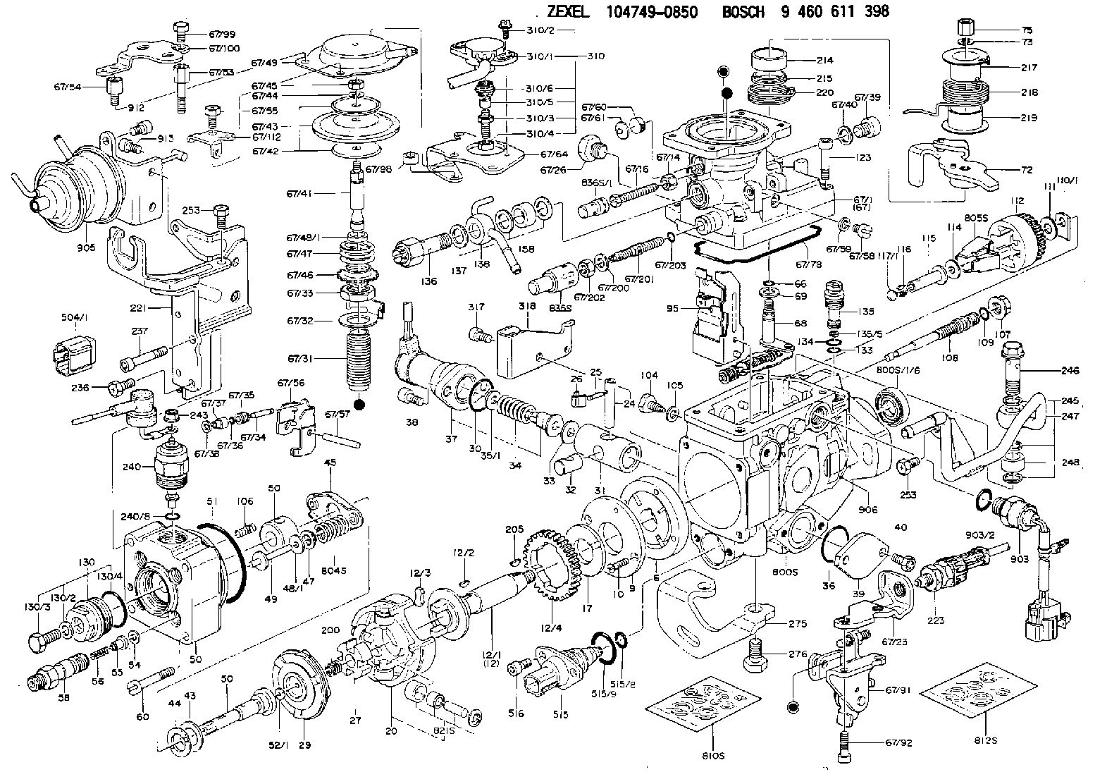
Information injection-pump assembly
BOSCH
9 460 611 398
9460611398
ZEXEL
104749-0850
1047490850
MAZDA
RFS513800D
rfs513800d

Rating:
Components :
| 0. | INJECTION-PUMP ASSEMBLY | 104749-0850 |
| 1. | _ | |
| 2. | FUEL INJECTION PUMP | 104649-0850 |
| 3. | NUMBER PLATE | 146990-8600 |
| 4. | _ | 146672-6320 |
| 5. | CAPSULE | |
| 6. | ADJUSTING DEVICE | 146679-4521 |
| 7. | NOZZLE AND HOLDER ASSY | 105140-1160 |
| 8. | Nozzle and Holder | RFS513H50A |
| 9. | Open Pre:MPa(Kqf/cm2) | 14.7{150} |
| 10. | NOZZLE-HOLDER | 105071-1530 |
| 11. | NOZZLE | 105000-2240 |
Scheme ###:
| 1/6. | [1] | 146601-0700 | PACKING RING |
| 6. | [1] | 146100-0120 | SUPPLY PUMP |
| 9. | [1] | 146103-0000 | COVER |
| 10. | [2] | 139104-0000 | FLAT-HEAD SCREW |
| 12. | [1] | 146200-0320 | DRIVE SHAFT |
| 12/1. | [1] | 146200-0300 | DRIVE SHAFT |
| 12/2. | [1] | 146201-0000 | WOODRUFF KEY |
| 12/3. | [2] | 146202-0100 | DAMPER |
| 12/4. | [1] | 146203-0000 | TOOTHED GEAR |
| 17. | [1] | 146204-0000 | PLAIN WASHER |
| 20. | [1] | 146210-4620 | ROLLER SET |
| 24. | [1] | 146303-0000 | BEARING PIN |
| 25. | [1] | 146304-0000 | BEARING PIN |
| 26. | [1] | 146305-0000 | CLAMPING BAND |
| 27. | [1] | 146205-0000 | SLOTTED WASHER |
| 29. | [1] | 146220-3820 | CAM PLATE |
| 30. | [1] | 146600-0800 | O-RING |
| 31. | [1] | 146300-1300 | PUMP PLUNGER |
| 32. | [1] | 146301-0000 | SLIDING PIECE |
| 33. | [1] | 146603-0700 | SHIM D17.5&7.5T0.60 |
| 34. | [1] | 146306-2200 | COMPRESSION SPRING |
| 35/1. | [0] | 146603-0700 | SHIM D17.5&7.5T0.60 |
| 35/1. | [0] | 146603-0800 | SHIM D17.5&7.5T0.70 |
| 35/1. | [0] | 146603-0900 | SHIM D17.5&7.5T0.90 |
| 35/1. | [0] | 146603-1000 | SHIM D17.5&7.5T1.00 |
| 35/1. | [0] | 146603-1100 | SHIM D17.5&7.5T1.20 |
| 35/1. | [0] | 146603-3600 | SHIM D17.5&7.5T2.40 |
| 36. | [1] | 146600-0800 | O-RING |
| 37. | [1] | 479773-9120 | TIMER PISTON SENSOR |
| 38. | [2] | 010206-2040 | HEX-SOCKET-HEAD CAP SCREW |
| 39. | [1] | 146310-0100 | COVER |
| 40. | [2] | 146620-5000 | BLEEDER SCREW |
| 43. | [1] | 146230-0000 | SHIM |
| 44. | [1] | 146230-0100 | PLAIN WASHER |
| 45. | [1] | 146231-0001 | SLOTTED WASHER |
| 47. | [2] | 146233-0000 | SLOTTED WASHER |
| 48/1. | [1] | 146603-0000 | SHIM D17.0&5.2T0.50 |
| 48/1. | [1] | 146603-0100 | SHIM D17.0&5.2T0.80 |
| 48/1. | [1] | 146603-0200 | SHIM D17.0&5.2T1.00 |
| 48/1. | [1] | 146603-0300 | SHIM D17.0&5.2T1.20 |
| 48/1. | [1] | 146603-0400 | SHIM D17.0&5.2T1.50 |
| 48/1. | [1] | 146603-0500 | SHIM D17.0&5.2T1.80 |
| 48/1. | [1] | 146603-0600 | SHIM D17.0&5.2T2.00 |
| 48/1. | [1] | 146690-1400 | SHIM D17&5.2T0.9 |
| 48/1. | [1] | 146690-1500 | SHIM D17&5.2T1.1 |
| 48/1. | [1] | 146690-1600 | SHIM D17&5.2T1.3 |
| 48/1. | [1] | 146690-1700 | SHIM D17&5.2T1.4 |
| 48/1. | [1] | 146690-1800 | SHIM D17&5.2T1.6 |
| 48/1. | [1] | 146690-1900 | SHIM D17&5.2T1.7 |
| 48/1. | [1] | 146690-5800 | SHIM |
| 48/1. | [1] | 146690-5900 | SHIM |
| 48/1. | [1] | 146690-6000 | SHIM |
| 48/1. | [1] | 146690-6100 | SHIM |
| 48/1. | [1] | 146690-6200 | SHIM |
| 48/1. | [1] | 146690-6300 | SHIM |
| 48/1. | [1] | 146690-6400 | SHIM |
| 48/1. | [1] | 146690-6500 | SHIM |
| 48/1. | [1] | 146690-6600 | SHIM |
| 48/1. | [1] | 146690-6700 | SHIM |
| 48/1. | [1] | 146690-6800 | SHIM |
| 48/1. | [1] | 146690-6900 | SHIM |
| 48/1. | [1] | 146690-7000 | SHIM |
| 48/1. | [1] | 146690-7100 | SHIM |
| 48/1. | [1] | 146690-7200 | SHIM |
| 48/1. | [1] | 146690-7300 | SHIM |
| 48/1. | [1] | 146690-7400 | SHIM |
| 48/1. | [1] | 146690-7500 | SHIM |
| 48/1. | [1] | 146690-7800 | SHIM |
| 49. | [2] | 146234-0020 | GUIDE PIN |
| 50. | [1] | 146403-1120 | HYDRAULIC HEAD |
| 50. | [1] | 146403-1120 | HYDRAULIC HEAD |
| 50. | [1] | 146403-1120 | HYDRAULIC HEAD |
| 51. | [1] | 146600-0000 | O-RING |
| 52/1. | [1] | 146420-0000 | SHIM D9.5&3.0T1.90 |
| 52/1. | [1] | 146420-0100 | SHIM D9.5&3.0T1.92 |
| 52/1. | [1] | 146420-0200 | SHIM D9.5&3.0T1.94 |
| 52/1. | [1] | 146420-0300 | SHIM D9.5&3.0T1.96 |
| 52/1. | [1] | 146420-0400 | SHIM D9.5&3.0T1.98 |
| 52/1. | [1] | 146420-0500 | SHIM D9.5&3.0T2.00 |
| 52/1. | [1] | 146420-0600 | SHIM D9.5&3.0T2.02 |
| 52/1. | [1] | 146420-0700 | SHIM D9.5&3.0T2.04 |
| 52/1. | [1] | 146420-0800 | SHIM D9.5&3.0T2.06 |
| 52/1. | [1] | 146420-0900 | SHIM D9.5&3.0T2.08 |
| 52/1. | [1] | 146420-1000 | SHIM D9.5&3.0T2.10 |
| 52/1. | [1] | 146420-1100 | SHIM D9.5&3.0T2.12 |
| 52/1. | [1] | 146420-1200 | SHIM D9.5&3.0T2.14 |
| 52/1. | [1] | 146420-1300 | SHIM D9.5&3.0T2.16 |
| 52/1. | [1] | 146420-1400 | SHIM D9.5&3.0T2.18 |
| 52/1. | [1] | 146420-1500 | SHIM D9.5&3.0T2.20 |
| 52/1. | [1] | 146420-1600 | SHIM D9.5&3.0T2.22 |
| 52/1. | [1] | 146420-1700 | SHIM D9.5&3.0T2.24 |
| 52/1. | [1] | 146420-1800 | SHIM D9.5&3.0T2.26 |
| 52/1. | [1] | 146420-1900 | SHIM D9.5&3.0T2.28 |
| 52/1. | [1] | 146420-2000 | SHIM D9.5&3.0T2.30 |
| 52/1. | [1] | 146420-2100 | SHIM D9.5&3.0T2.32 |
| 52/1. | [1] | 146420-2200 | SHIM D9.5&3.0T2.34 |
| 52/1. | [1] | 146420-2300 | SHIM D9.5&3.0T2.36 |
| 52/1. | [1] | 146420-2400 | SHIM D9.5&3.0T2.38 |
| 52/1. | [1] | 146420-2500 | SHIM D9.5&3.0T2.40 |
| 52/1. | [1] | 146420-2600 | SHIM D9.5&3.0T2.42 |
| 52/1. | [1] | 146420-2700 | SHIM D9.5&3.0T2.44 |
| 52/1. | [1] | 146420-2800 | SHIM D9.5&3.0T2.46 |
| 52/1. | [1] | 146420-2900 | SHIM D9.5&3.0T2.48 |
| 52/1. | [1] | 146420-3000 | SHIM D9.5&3.0T2.50 |
| 52/1. | [1] | 146420-3100 | SHIM D9.5&3.0T2.52 |
| 52/1. | [1] | 146420-3200 | SHIM D9.5&3.0T2.54 |
| 52/1. | [1] | 146420-3300 | SHIM D9.5&3.0T2.56 |
| 52/1. | [1] | 146420-3400 | SHIM D9.5&3.0T2.58 |
| 52/1. | [1] | 146420-3500 | SHIM D9.5&3.0T2.60 |
| 52/1. | [1] | 146420-3600 | SHIM D9.5&3.0T2.62 |
| 52/1. | [1] | 146420-3700 | SHIM D9.5&3.0T2.64 |
| 52/1. | [1] | 146420-3800 | SHIM D9.5&3.0T2.66 |
| 52/1. | [1] | 146420-3900 | SHIM D9.5&3.0T2.68 |
| 52/1. | [1] | 146420-4000 | SHIM D9.5&3.0T2.70 |
| 52/1. | [1] | 146420-4100 | SHIM D9.5&3.0T2.72 |
| 52/1. | [1] | 146420-4200 | SHIM D9.5&3.0T2.74 |
| 52/1. | [1] | 146420-4300 | SHIM D9.5&3.0T2.76 |
| 52/1. | [1] | 146420-4400 | SHIM D9.5&3.0T2.78 |
| 52/1. | [1] | 146420-4500 | SHIM D9.5&3.0T2.80 |
| 52/1. | [1] | 146420-4600 | SHIM D9.5&3.0T2.82 |
| 52/1. | [1] | 146420-4700 | SHIM D9.5&3.0T2.84 |
| 52/1. | [1] | 146420-4800 | SHIM D9.5&3.0T2.86 |
| 52/1. | [1] | 146420-4900 | SHIM D9.5&3.0T2.88 |
| 52/1. | [1] | 146420-5000 | SHIM D9.5&3.0T2.90 |
| 52/1. | [1] | 146420-5100 | SHIM D9.5&3.0T1.74 |
| 52/1. | [1] | 146420-5200 | SHIM D9.5&3.0T1.76 |
| 52/1. | [1] | 146420-5300 | SHIM D9.5&3.0T1.78 |
| 52/1. | [1] | 146420-5400 | SHIM D9.5&3.0T1.80 |
| 52/1. | [1] | 146420-5500 | SHIM D9.5&3.0T1.82 |
| 52/1. | [1] | 146420-5600 | SHIM D9.5&3.0T1.84 |
| 52/1. | [1] | 146420-5700 | SHIM D9.5&3.0T1.86 |
| 52/1. | [1] | 146420-5800 | SHIM D9.5&3.0T1.88 |
| 54. | [4] | 146433-0100 | GASKET D12&6.4T1.00 |
| 55. | [4] | 146430-2420 | DELIVERY-VALVE ASSEMBLY |
| 56. | [4] | 146432-0000 | COMPRESSION SPRING |
| 58. | [4] | 146440-0220 | FITTING |
| 60. | [3] | 139106-0100 | FLAT-HEAD SCREW |
| 66. | [1] | 146600-0100 | O-RING |
| 67. | [1] | 146760-2520 | MANIFOLD-PRESSURE COMP. |
| 67/1. | [1] | 146805-4320 | GOVERNOR COVER |
| 67/14. | [1] | 146621-1700 | UNION NUT |
| 67/16. | [1] | 146526-3000 | BLEEDER SCREW |
| 67/23. | [1] | 146933-5300 | BRACKET |
| 67/26. | [1] | 146507-0300 | ADAPTOR |
| 67/31. | [1] | 146710-0800 | BUSHING |
| 67/32. | [1] | 146711-0000 | PLATE |
| 67/33. | [1] | 139218-0400 | UNION NUT |
| 67/34. | [1] | 146712-0700 | BEARING PIN |
| 67/35. | [1] | 146621-0300 | UNION NUT |
| 67/36. | [1] | 146600-1400 | O-RING |
| 67/37. | [1] | 146710-0100 | BUSHING |
| 67/38. | [1] | 139506-0200 | GASKET D8.9&6.8T1.00 |
| 67/39. | [1] | 146620-0300 | CAPSULE |
| 67/40. | [1] | 026512-1540 | GASKET D15.4&12.2T1.50 |
| 67/41. | [1] | 146713-4100 | ADJUSTING PIN |
| 67/42. | [2] | 146714-0000 | PLATE |
| 67/43. | [1] | 146715-0000 | DIAPHRAGM |
| 67/44. | [1] | 139306-0100 | LOCKING WASHER |
| 67/45. | [1] | 013030-6040 | UNION NUT M6P1H3.6 |
| 67/46. | [1] | 146716-0000 | UNION NUT |
| 67/47. | [1] | 146717-1100 | COILED SPRING |
| 67/48/1. | [1] | 146720-0000 | SPACER BUSHING L3.7 |
| 67/48/1. | [1] | 146720-0100 | SPACER BUSHING L3.9 |
| 67/48/1. | [1] | 146720-0200 | SPACER BUSHING L4.1 |
| 67/48/1. | [1] | 146720-0300 | SPACER BUSHING L4.3 |
| 67/48/1. | [1] | 146720-0400 | SPACER BUSHING L4.5 |
| 67/48/1. | [1] | 146720-0500 | SPACER BUSHING L4.7 |
| 67/48/1. | [1] | 146720-0600 | SPACER BUSHING L4.9 |
| 67/48/1. | [1] | 146720-0700 | SPACER BUSHING L5.1 |
| 67/48/1. | [1] | 146720-0800 | SPACER BUSHING L5.3 |
| 67/48/1. | [1] | 146720-0900 | SPACER BUSHING L2.7 |
| 67/48/1. | [1] | 146720-1000 | SPACER BUSHING L2.9 |
| 67/48/1. | [1] | 146720-1100 | SPACER BUSHING L3.1 |
| 67/48/1. | [1] | 146720-1200 | SPACER BUSHING L3.3 |
| 67/48/1. | [1] | 146720-1300 | SPACER BUSHING L3.5 |
| 67/48/1. | [1] | 146720-1400 | SPACER BUSHING L2.8 |
| 67/48/1. | [1] | 146720-1500 | SPACER BUSHING L3.0 |
| 67/48/1. | [1] | 146720-1600 | SPACER BUSHING L3.2 |
| 67/48/1. | [1] | 146720-1700 | SPACER BUSHING L3.4 |
| 67/48/1. | [1] | 146720-1800 | SPACER BUSHING L3.6 |
| 67/48/1. | [1] | 146720-1900 | SPACER BUSHING L3.8 |
| 67/48/1. | [1] | 146720-2000 | SPACER BUSHING L4.0 |
| 67/48/1. | [1] | 146720-2100 | SPACER BUSHING L4.2 |
| 67/48/1. | [1] | 146720-2200 | SPACER BUSHING L4.4 |
| 67/48/1. | [1] | 146720-2300 | SPACER BUSHING L4.6 |
| 67/48/1. | [1] | 146720-2400 | SPACER BUSHING L4.8 |
| 67/48/1. | [1] | 146720-2500 | SPACER BUSHING L5.0 |
| 67/48/1. | [1] | 146720-2600 | SPACER BUSHING L5.2 |
| 67/48/1. | [1] | 146720-2700 | SPACER BUSHING L5.4 |
| 67/48/1. | [1] | 146720-2800 | SPACER BUSHING L5.5 |
| 67/48/1. | [1] | 146720-2900 | SPACER BUSHING L5.6 |
| 67/48/1. | [1] | 146720-4500 | SPACER BUSHING L1.8 |
| 67/48/1. | [1] | 146720-4600 | SPACER BUSHING L1.9 |
| 67/48/1. | [1] | 146720-4700 | SPACER BUSHING L2.0 |
| 67/48/1. | [1] | 146720-4800 | SPACER BUSHING L2.1 |
| 67/48/1. | [1] | 146720-4900 | SPACER BUSHING L2.2 |
| 67/48/1. | [1] | 146720-5000 | SPACER BUSHING L2.3 |
| 67/48/1. | [1] | 146720-5100 | SPACER BUSHING L2.4 |
| 67/48/1. | [1] | 146720-5200 | SPACER BUSHING L2.5 |
| 67/48/1. | [1] | 146720-5300 | SPACER BUSHING L2.6 |
| 67/48/1. | [1] | 146725-2500 | SPACER BUSHING L5.7 |
| 67/48/1. | [1] | 146725-2600 | SPACER BUSHING L5.8 |
| 67/48/1. | [1] | 146725-2700 | SPACER BUSHING L5.9 |
| 67/48/1. | [1] | 146725-2800 | SPACER BUSHING L6.0 |
| 67/48/1. | [1] | 146725-2900 | SPACER BUSHING L6.1 |
| 67/48/1. | [1] | 146725-3000 | SPACER BUSHING L6.2 |
| 67/48/1. | [1] | 146725-3100 | SPACER BUSHING L6.3 |
| 67/48/1. | [1] | 146725-3200 | SPACER BUSHING L6.4 |
| 67/48/1. | [1] | 146725-3300 | SPACER BUSHING L6.5 |
| 67/48/1. | [1] | 146725-3400 | SPACER BUSHING L6.6 |
| 67/48/1. | [1] | 146725-3500 | SPACER BUSHING L6.7 |
| 67/48/1. | [1] | 146725-3600 | SPACER BUSHING L6.8 |
| 67/48/1. | [1] | 146725-3700 | SPACER BUSHING L6.9 |
| 67/48/1. | [1] | 146725-3800 | SPACER BUSHING L7.0 |
| 67/48/1. | [1] | 146725-3900 | SPACER BUSHING L7.1 |
| 67/48/1. | [1] | 146725-4000 | SPACER BUSHING L7.2 |
| 67/48/1. | [1] | 146725-4100 | SPACER BUSHING L7.3 |
| 67/48/1. | [1] | 146725-4200 | SPACER BUSHING L7.4 |
| 67/48/1. | [1] | 146725-4300 | SPACER BUSHING L7.5 |
| 67/49. | [1] | 146721-2120 | COVER |
| 67/53. | [1] | 146620-6800 | BLEEDER SCREW |
| 67/54. | [1] | 146620-6100 | BLEEDER SCREW |
| 67/55. | [2] | 139006-4500 | BLEEDER SCREW |
| 67/56. | [1] | 146723-0300 | CONTROL LEVER |
| 67/57. | [1] | 146712-0100 | BEARING PIN |
| 67/58. | [2] | 146620-0600 | CAPSULE |
| 67/59. | [2] | 026506-1040 | GASKET D9.9&6.2T1 |
| 67/60. | [1] | 146724-0300 | ELEMENT |
| 67/61. | [1] | 146724-0600 | CAPSULE |
| 67/64. | [1] | 146930-1900 | BRACKET |
| 67/78. | [1] | 146600-4400 | SEAL RING |
| 67/91. | [1] | 146933-5420 | BRACKET |
| 67/92. | [2] | 010206-2540 | HEX-SOCKET-HEAD CAP SCREW M6P1L25 |
| 67/98. | [1] | 146648-2800 | SPACER BUSHING |
| 67/99. | [2] | 010006-0870 | BLEEDER SCREW M6P1L8 7T |
| 67/100. | [1] | 146930-2000 | BRACKET |
| 67/112. | [1] | 146930-2100 | BRACKET |
| 67/200. | [1] | 139308-0300 | PLAIN WASHER |
| 67/201. | [1] | 146545-4100 | THREADED PIN |
| 67/201B. | [1] | 146545-4200 | THREADED PIN |
| 67/201C. | [1] | 146545-4300 | THREADED PIN |
| 67/202. | [1] | 139208-0900 | UNION NUT |
| 67/203. | [1] | 146600-1200 | O-RING |
| 68. | [1] | 146514-4320 | CONTROL SHAFT |
| 69. | [1] | 139310-0200 | PLAIN WASHER |
| 72. | [1] | 146831-5920 | CONTROL LEVER |
| 72B. | [1] | 146831-6020 | CONTROL LEVER |
| 72C. | [1] | 146831-6120 | CONTROL LEVER |
| 72D. | [1] | 146831-6220 | CONTROL LEVER |
| 73. | [1] | 014110-6440 | LOCKING WASHER |
| 75. | [1] | 146621-0700 | UNION NUT |
| 95. | [1] | 146851-4420 | FULCRUM LEVER |
| 104. | [2] | 146568-0000 | SLOTTED SPRING PIN |
| 105. | [2] | 026508-1140 | GASKET D11.4&8.2T1 |
| 106. | [2] | 146588-0500 | COILED SPRING |
| 107. | [1] | 146569-0300 | UNION NUT |
| 108. | [1] | 146570-0100 | GOVERNOR SHAFT |
| 109. | [1] | 146600-0400 | O-RING |
| 110/1. | [1] | 146571-0000 | SHIM D20.2&8.3T1.05 |
| 110/1. | [1] | 146571-0100 | SHIM D20.2&8.3T1.25 |
| 110/1. | [1] | 146571-0200 | SHIM D20.2&8.3T1.45 |
| 110/1. | [1] | 146571-0300 | SHIM D20.2&8.3T1.65 |
| 110/1. | [1] | 146571-0400 | SHIM D20.2&8.3T1.85 |
| 110/1. | [1] | 146571-0500 | SHIM D20.2&8.3T1.15 |
| 110/1. | [1] | 146571-0600 | SHIM D20.2&8.3T1.35 |
| 110/1. | [1] | 146571-0700 | SHIM D20.2&8.3T1.55 |
| 110/1. | [1] | 146571-0800 | SHIM D20.2&8.3T1.75 |
| 111. | [1] | 146602-0600 | PLAIN WASHER D20&8.4T1.40 |
| 112. | [1] | 146572-0020 | FLYWEIGHT ASSEMBLY |
| 114. | [1] | 146602-0500 | PLAIN WASHER D17&6.4T1.60 |
| 115. | [1] | 146975-4200 | SLIDING SLEEVE |
| 116. | [1] | 146576-0200 | CAP |
| 117/1. | [1] | 146577-1800 | PLUG L2.10 |
| 117/1. | [1] | 146577-1900 | PLUG L2.30 |
| 117/1. | [1] | 146577-2000 | PLUG L2.50 |
| 117/1. | [1] | 146577-2100 | PLUG L2.70 |
| 117/1. | [1] | 146577-2200 | PLUG L2.90 |
| 117/1. | [1] | 146577-2300 | PLUG L3.10 |
| 117/1. | [1] | 146577-2400 | PLUG L3.30 |
| 117/1. | [1] | 146577-2500 | PLUG L3.50 |
| 117/1. | [1] | 146577-2600 | PLUG L3.70 |
| 117/1. | [1] | 146577-2700 | PLUG L3.90 |
| 117/1. | [1] | 146577-2800 | PLUG L4.10 |
| 117/1. | [1] | 146577-2900 | PLUG L4.30 |
| 117/1. | [1] | 146577-3000 | PLUG L4.50 |
| 117/1. | [1] | 146577-3100 | PLUG L4.70 |
| 117/1. | [1] | 146577-3200 | PLUG L4.90 |
| 117/1. | [1] | 146577-3300 | PLUG L5.10 |
| 117/1. | [1] | 146577-6700 | PLUG L2.2 |
| 117/1. | [1] | 146577-6800 | PLUG L2.4 |
| 117/1. | [1] | 146577-6900 | PLUG L2.6 |
| 117/1. | [1] | 146577-7000 | PLUG L2.8 |
| 117/1. | [1] | 146577-7100 | PLUG L3.0 |
| 117/1. | [1] | 146577-7200 | PLUG L3.2 |
| 117/1. | [1] | 146577-7300 | PLUG L3.4 |
| 117/1. | [1] | 146577-7400 | PLUG L3.6 |
| 117/1. | [1] | 146577-7500 | PLUG L3.8 |
| 117/1. | [1] | 146577-7600 | PLUG L4.0 |
| 117/1. | [1] | 146577-7700 | PLUG L4.2 |
| 117/1. | [1] | 146577-7800 | PLUG L4.4 |
| 117/1. | [1] | 146577-7900 | PLUG L4.6 |
| 117/1. | [1] | 146577-8000 | PLUG L4.8 |
| 117/1. | [1] | 146577-8100 | PLUG L5.0 |
| 117/1. | [1] | 146877-0000 | PLUG L5.2 |
| 117/1. | [1] | 146877-0100 | PLUG L5.3 |
| 117/1. | [1] | 146877-0200 | PLUG L5.4 |
| 117/1. | [1] | 146877-0300 | PLUG L5.5 |
| 117/1. | [1] | 146877-4700 | PLUG |
| 117/1. | [1] | 146877-4800 | PLUG |
| 117/1. | [1] | 146877-4900 | PLUG |
| 117/1. | [1] | 146877-5000 | PLUG |
| 123. | [4] | 146620-0500 | HEX-SOCKET-HEAD CAP SCREW |
| 130. | [1] | 146421-0020 | CAPSULE |
| 130/2. | [1] | 026508-1140 | GASKET D11.4&8.2T1 |
| 130/3. | [1] | 146422-0000 | BLEEDER SCREW |
| 130/4. | [1] | 146600-0500 | O-RING |
| 133. | [1] | 146600-0600 | O-RING |
| 134. | [1] | 146600-0700 | O-RING |
| 135. | [1] | 146110-3220 | CONTROL VALVE |
| 135/5. | [1] | 146114-0000 | SPRING WASHER |
| 136. | [1] | 148120-0020 | OVER FLOW VALVE |
| 137. | [3] | 139512-0500 | GASKET |
| 138. | [1] | 146668-3120 | INLET UNION |
| 158. | [1] | 146614-6900 | SPACER BUSHING |
| 200. | [1] | 146206-0100 | COILED SPRING |
| 205. | [1] | 029470-4030 | WOODRUFF KEY |
| 214. | [1] | 146542-1400 | BUSHING |
| 215. | [1] | 146542-1500 | BUSHING |
| 217. | [1] | 146542-5700 | SLOTTED WASHER |
| 218. | [1] | 146592-4500 | COILED SPRING |
| 219. | [1] | 146541-3000 | BUSHING |
| 220. | [1] | 146592-4900 | COILED SPRING |
| 221. | [1] | 146933-6820 | BRACKET |
| 223. | [1] | 146670-9620 | SWITCH |
| 236. | [1] | 139006-4800 | BLEEDER SCREW |
| 237. | [1] | 146620-0200 | HEX-SOCKET-HEAD CAP SCREW |
| 240. | [1] | 146650-4320 | PULLING ELECTROMAGNET |
| 240/8. | [1] | 146600-1700 | O-RING |
| 243. | [1] | 146621-1000 | UNION NUT |
| 245. | [3] | 139512-0500 | GASKET |
| 246. | [1] | 139812-1900 | EYE BOLT |
| 247. | [1] | 146665-7520 | INLET UNION |
| 248. | [1] | 146614-0200 | SPACER BUSHING |
| 253. | [2] | 139006-4400 | BLEEDER SCREW |
| 253. | [2] | 139006-4400 | BLEEDER SCREW |
| 275. | [1] | 146612-7620 | BRACKET |
| 276. | [2] | 010010-1640 | BLEEDER SCREW M10P1.5L16 4T |
| 310. | [1] | 146684-8220 | POTENTCIOMETER |
| 310/1. | [1] | 146684-8210 | POTENTCIOMETER |
| 310/2. | [2] | 139104-0400 | FLAT-HEAD SCREW |
| 310/3. | [1] | 146620-1500 | FLAT-HEAD SCREW |
| 310/4. | [1] | 013020-6040 | UNION NUT M6P1H5 |
| 310/5. | [1] | 146614-2300 | JOINT CONNECTION |
| 310/6. | [1] | 146661-0401 | BOOT |
| 317. | [1] | 010206-1040 | HEX-SOCKET-HEAD CAP SCREW |
| 318. | [1] | 146933-5900 | BRACKET |
| 504/1. | [1] | 146649-4500 | RESISTER |
| 504/1. | [1] | 146649-4600 | RESISTER |
| 504/1. | [1] | 146649-4700 | RESISTER |
| 504/1. | [1] | 146649-4800 | RESISTER |
| 504/1. | [1] | 146649-4900 | RESISTER |
| 504/1. | [1] | 146649-5000 | RESISTER |
| 504/1. | [1] | 146649-5100 | RESISTER |
| 504/1. | [1] | 146649-5200 | RESISTER |
| 504/1. | [1] | 146649-5300 | RESISTER |
| 504/1. | [1] | 146649-5400 | RESISTER |
| 504/1. | [1] | 146649-5500 | RESISTER |
| 504/1. | [1] | 146649-5600 | RESISTER |
| 504/1. | [1] | 146649-5700 | RESISTER |
| 515. | [1] | 106144-1070 | TIMING CONTROL VALVE |
| 515/8. | [1] | 161440-3800 | O-RING |
| 515/9. | [1] | 161440-3700 | O-RING |
| 516. | [2] | 010206-1440 | HEX-SOCKET-HEAD CAP SCREW M6P1L14 |
| 800S. | [1] | 146018-5420 | PUMP HOUSING |
| 800S/1/6. | [1] | 146601-0700 | PACKING RING |
| 804S. | [1] | 146232-0220 | COMPRESSION SPRING |
| 805S. | [1] | 146574-0120 | PARTS SET |
| 810S. | [1] | 146600-2420 | REPAIR SET |
| 812S. | [1] | 146600-1920 | PARTS SET |
| 821S. | [1] | 146210-5820 | ROLLER SET |
| 835S. | [1] | 146598-1000 | CAP |
| 836S/1. | [1] | 146598-0600 | CAP L18 |
| 836S/1. | [1] | 146598-0700 | CAP L21 |
| 836S/1. | [1] | 146598-0800 | CAP L24 |
| 836S/1. | [1] | 146598-0900 | CAP L27 |
| 903. | [1] | 146672-6320 | PULSE GENERATOR |
| 903/2. | [1] | 146600-1300 | O-RING &13W1.9 |
| 905. | [1] | 146679-4521 | ACTUATOR |
| 906. | [1] | 146990-8600 | NAMEPLATE |
| 912. | [2] | 010206-1240 | HEX-SOCKET-HEAD CAP SCREW M6P1L12 |
| 913. | [1] | 010206-2040 | HEX-SOCKET-HEAD CAP SCREW |
Include in #2:
104749-0850
as INJECTION-PUMP ASSEMBLY
Cross reference number
BOSCH
9 460 611 398
9460611398
ZEXEL
104749-0850
1047490850
MAZDA
RFS513800D
rfs513800d
Zexel num
Bosch num
Firm num
Name
104749-0850
9 460 611 398
RFS513800D MAZDA
INJECTION-PUMP ASSEMBLY
RFX K 11CL INJECTION PUMP ASSY COVEC 4 COVEC
RFX K 11CL INJECTION PUMP ASSY COVEC 4 COVEC
Calibration Data:
Adjustment conditions
Test oil
1404 Test oil ISO4113orSAEJ967d
1404 Test oil ISO4113orSAEJ967d
Test oil temperature
degC
45
45
50
Nozzle
105780-0060
Bosch type code
NP-DN0SD1510
Nozzle holder
105780-2150
Opening pressure
MPa
13
13
13.3
Opening pressure
kgf/cm2
133
133
136
Injection pipe
157805-7320
Injection pipe
Inside diameter - outside diameter - length (mm) mm 2-6-450
Inside diameter - outside diameter - length (mm) mm 2-6-450
Joint assembly
157641-4720
Tube assembly
157641-4020
Transfer pump pressure
kPa
20
20
20
Transfer pump pressure
kgf/cm2
0.2
0.2
0.2
Direction of rotation (viewed from drive side)
Right R
Right R
Injection timing adjustment
Pump speed
r/min
1000
1000
1000
Boost pressure
kPa
40
38.7
41.3
Boost pressure
mmHg
300
290
310
Average injection quantity
mm3/st.
46.5
46
47
Difference in delivery
mm3/st.
3.5
Basic
*
Oil temperature
degC
50
48
52
Remarks
CBS
CBS
Injection timing adjustment_02
Pump speed
r/min
1000
1000
1000
Boost pressure
kPa
86.6
85.3
87.9
Boost pressure
mmHg
650
640
660
Average injection quantity
mm3/st.
50.8
50.3
51.3
Difference in delivery
mm3/st.
4
Basic
*
Oil temperature
degC
50
48
52
Remarks
Full
Full
Injection timing adjustment_03
Pump speed
r/min
600
600
600
Boost pressure
kPa
46.7
45.4
48
Boost pressure
mmHg
350
340
360
Average injection quantity
mm3/st.
42.6
40.1
45.1
Oil temperature
degC
50
48
52
Injection timing adjustment_04
Pump speed
r/min
1000
1000
1000
Boost pressure
kPa
0
0
0
Boost pressure
mmHg
0
0
0
Average injection quantity
mm3/st.
39.6
37.1
42.1
Oil temperature
degC
50
48
52
Injection timing adjustment_05
Pump speed
r/min
1000
1000
1000
Boost pressure
kPa
40
38.7
41.3
Boost pressure
mmHg
300
290
310
Average injection quantity
mm3/st.
46.5
45.5
47.5
Difference in delivery
mm3/st.
4
Oil temperature
degC
50
48
52
Injection timing adjustment_06
Pump speed
r/min
1000
1000
1000
Boost pressure
kPa
86.6
85.3
87.9
Boost pressure
mmHg
650
640
660
Average injection quantity
mm3/st.
50.8
49.8
51.8
Difference in delivery
mm3/st.
4.5
Oil temperature
degC
50
48
52
Injection timing adjustment_07
Pump speed
r/min
2150
2150
2150
Boost pressure
kPa
86.6
85.3
87.9
Boost pressure
mmHg
650
640
660
Average injection quantity
mm3/st.
42.9
40.4
45.4
Oil temperature
degC
52
50
54
Injection quantity adjustment
Pump speed
r/min
2250
2250
2250
Boost pressure
kPa
86.6
85.3
87.9
Boost pressure
mmHg
650
640
660
Average injection quantity
mm3/st.
37
35
39
Basic
*
Oil temperature
degC
52
50
54
Injection quantity adjustment_02
Pump speed
r/min
2700
2700
2700
Boost pressure
kPa
86.6
85.3
87.9
Boost pressure
mmHg
650
640
660
Average injection quantity
mm3/st.
5
Oil temperature
degC
55
52
58
Injection quantity adjustment_03
Pump speed
r/min
2250
2250
2250
Boost pressure
kPa
86.6
85.3
87.9
Boost pressure
mmHg
650
640
660
Average injection quantity
mm3/st.
37
34.5
39.5
Oil temperature
degC
52
50
54
Injection quantity adjustment_04
Pump speed
r/min
2550
2550
2550
Boost pressure
kPa
86.6
85.3
87.9
Boost pressure
mmHg
650
640
660
Average injection quantity
mm3/st.
10
6.5
13.5
Oil temperature
degC
55
52
58
Governor adjustment
Pump speed
r/min
360
360
360
Boost pressure
kPa
0
0
0
Boost pressure
mmHg
0
0
0
Average injection quantity
mm3/st.
10.2
9.2
11.2
Difference in delivery
mm3/st.
2
Basic
*
Oil temperature
degC
48
46
50
Governor adjustment_02
Pump speed
r/min
360
360
360
Boost pressure
kPa
0
0
0
Boost pressure
mmHg
0
0
0
Average injection quantity
mm3/st.
10.2
8.7
11.7
Difference in delivery
mm3/st.
2.5
Oil temperature
degC
48
46
50
Timer adjustment
Pump speed
r/min
100
100
100
Boost pressure
kPa
0
0
0
Boost pressure
mmHg
0
0
0
Average injection quantity
mm3/st.
60.3
50.3
70.3
Basic
*
Oil temperature
degC
48
46
50
Remarks
Full
Full
Timer adjustment_02
Pump speed
r/min
100
100
100
Boost pressure
kPa
0
0
0
Boost pressure
mmHg
0
0
0
Average injection quantity
mm3/st.
60.3
45.3
75.3
Oil temperature
degC
48
46
50
Speed control lever angle
Pump speed
r/min
360
360
360
Boost pressure
kPa
0
0
0
Boost pressure
mmHg
0
0
0
Average injection quantity
mm3/st.
0
0
0
Oil temperature
degC
48
46
50
Remarks
Magnet OFF at idling position
Magnet OFF at idling position
0000000901
Pump speed
r/min
1000
1000
1000
Boost pressure
kPa
86.6
85.3
87.9
Boost pressure
mmHg
650
640
660
Overflow quantity
cm3/min
600
470
730
Oil temperature
degC
50
48
52
Stop lever angle
Pump speed
r/min
500
500
500
Boost pressure
kPa
86.6
85.3
87.9
Boost pressure
mmHg
650
640
660
Pressure
kPa
392
390
394
Pressure
kgf/cm2
4
3.7
4.3
Basic
*
Oil temperature
degC
48
46
50
Stop lever angle_02
Pump speed
r/min
500
500
500
Boost pressure
kPa
86.6
85.3
87.9
Boost pressure
mmHg
650
640
660
Pressure
kPa
392
353
431
Pressure
kgf/cm2
4
3.6
4.4
Oil temperature
degC
48
46
50
0000001101
Pump speed
r/min
1000
1000
1000
Boost pressure
kPa
86.6
85.3
87.9
Boost pressure
mmHg
650
640
660
TCV duty (%) F TCV 60Hz
%
100
100
100
Timer stroke with S/T ON
mm
8
7.8
8.2
Basic
*
Oil temperature
degC
50
48
52
_02
Pump speed
r/min
100
100
100
Boost pressure
kPa
86.6
85.3
87.9
Boost pressure
mmHg
650
640
660
TCV duty (%) F TCV 60Hz
%
100
100
100
Timer stroke
mm
2.3
2.3
Oil temperature
degC
48
46
50
_03
Pump speed
r/min
500
500
500
Boost pressure
kPa
86.6
85.3
87.9
Boost pressure
mmHg
650
640
660
TCV duty (%) F TCV 60Hz
%
100
100
100
Timer stroke
mm
5.3
5.3
Oil temperature
degC
48
46
50
_04
Pump speed
r/min
1000
1000
1000
Boost pressure
kPa
86.6
85.3
87.9
Boost pressure
mmHg
650
640
660
TCV duty (%) F TCV 60Hz
%
100
100
100
Timer stroke
mm
8
8
8
Oil temperature
degC
50
48
52
_05
Pump speed
r/min
2150
2150
2150
Boost pressure
kPa
86.6
85.3
87.9
Boost pressure
mmHg
650
640
660
TCV duty (%) F TCV 60Hz
%
100
100
100
Timer stroke
mm
11.4
11.4
11.4
Oil temperature
degC
52
50
54
0000001301
Max. applied voltage
V
8
8
8
Test voltage
V
13
12
14
0000002701
K dimension
mm
3.3
3.2
3.4
KF dimension
mm
5.8
5.7
5.9
MS dimension
mm
1.5
1.4
1.6
BCS stroke
mm
4
3.8
4.2
Pre-stroke
mm
0.3
0.28
0.32
Control lever angle alpha
deg.
25
21
29
Control lever angle beta
deg.
41
38
44
Test data Ex:
0000001901 TIMER PISTON SEVSOR ADJ
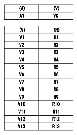
TPS (timer piston sensor) adjustment
Use the special circuit (corresponding to H) to measure TPS output voltage.
(1)Measure the TPS output voltage for zero compensation (no resistance).
(A): timer stroke TA
(V): compensation zero TPS output voltage (VTPS)
(2)Compensation resistor installation:
From the table, select and install a compensation resistor so that the compensation output voltage value is zero.
(R): selected compensation resistance
----------
H=479040-5600
----------
A1=0mm V0=0.510+-0.128V V1=0.382~0.401V V2=0.402~0.421V V3=0.422~0.440V V4=0.441~0.460V V5=0.461~0.479V V6=0.480~0.499V V7=0.500~0.519V V8=0.520~0.539V V9=0.540~0.558V V10=0.559~0.578V V11=0.579~0.597V V12=0.598~0.617V V13=0.618~0.637V R1=No.1,0.18kohm R2=No.2,0.30kohm R3=No.3,0.43kohm R4=No.4,0.62kohm R5=No.5,0.82kohm R6=No.6,1.10kohm R7=No.7,1.50kohm R8=No.8,2.00kohm R9=No.9,2.70kohm R10=No.10,3.90kohm R11=No.11,5.60kohm R12=No.12,8.20kohm R13=No.13,15.00kohm
----------
H=479040-5600
----------
A1=0mm V0=0.510+-0.128V V1=0.382~0.401V V2=0.402~0.421V V3=0.422~0.440V V4=0.441~0.460V V5=0.461~0.479V V6=0.480~0.499V V7=0.500~0.519V V8=0.520~0.539V V9=0.540~0.558V V10=0.559~0.578V V11=0.579~0.597V V12=0.598~0.617V V13=0.618~0.637V R1=No.1,0.18kohm R2=No.2,0.30kohm R3=No.3,0.43kohm R4=No.4,0.62kohm R5=No.5,0.82kohm R6=No.6,1.10kohm R7=No.7,1.50kohm R8=No.8,2.00kohm R9=No.9,2.70kohm R10=No.10,3.90kohm R11=No.11,5.60kohm R12=No.12,8.20kohm R13=No.13,15.00kohm
0000002001 POTENTIOMETER ADJUSTMENT
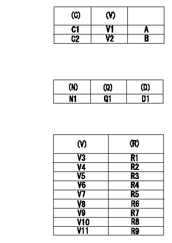
Adjustment of the potentiometer
(1)Potentiometer setting:
A = adjusting point
B = check point
(C) = control lever position
(V) = P/M output voltage
(2)Dummy bolt setting:
Fix the control lever with the dummy bolt so that the injection quantity is as shown in the following table at the pump speed = N1.
(N) = pump speed
(Q) = injection quantity
(D) = target lever angle
C1 = full speed position
C2 = idle position
(3)Read the output voltage (V) of the potentiometer in the state indicated in (2) above. Then, select the compensation resistor from the following table and replace.
(R) = compensation resistance
Note
As the output voltage is compensated in the control unit after replacing the compensation resistor, confirmation is not necessary.
----------
N1=1,000r/min
----------
V1=9.10+-0.03V V2=2.26+-0.7V N1=1000r/min Q1=24.2+-1.0cm3/1000st D1=(17)deg V3=4.96~5.07V V4=5.08~5.19V V5=5.20~5.31V V6=5.32~5.43V V7=5.44~5.55V V8=5.56~5.67V V9=5.68~5.79V V10=5.80~5.91V V11=5.92~6.03V R1=No.1,0.18k?? R2=No.2,0.30k?? R3=No.3,0.43k?? R4=No.4,0.62k?? R5=No.5,0.82k?? R6=No.6,1.10k?? R7=No.7,1.50k?? R8=No.8,2.00k?? R9=No.9,2.70k??
----------
N1=1,000r/min
----------
V1=9.10+-0.03V V2=2.26+-0.7V N1=1000r/min Q1=24.2+-1.0cm3/1000st D1=(17)deg V3=4.96~5.07V V4=5.08~5.19V V5=5.20~5.31V V6=5.32~5.43V V7=5.44~5.55V V8=5.56~5.67V V9=5.68~5.79V V10=5.80~5.91V V11=5.92~6.03V R1=No.1,0.18k?? R2=No.2,0.30k?? R3=No.3,0.43k?? R4=No.4,0.62k?? R5=No.5,0.82k?? R6=No.6,1.10k?? R7=No.7,1.50k?? R8=No.8,2.00k?? R9=No.9,2.70k??
0000002101 WIRE
Confirmation of the wire length:
Accelerator wire: Idle-full stroke: L1
Confirmation on the idle SW
Confirm that the switch is ON at the idle lever position.
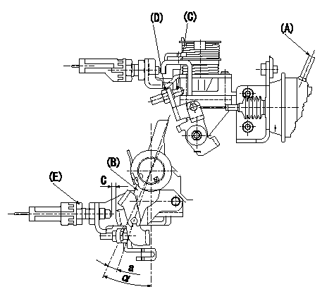
Adjustment of the double stage actuator:
(1)Apply negative pressure P1 {P2} to the actuator through the negative pressure inlet port.
(2)In status (1) above, adjust the intermediate lever screw C so that the control lever B position is a (ie, the distance between the control lever and the idle switch E is C). Fix using nut D.
TT
(Reference)
Actuator stroke;
(1)First step: L3
(2)Second stage: L4
----------
L1=32.0+-3.0mm C=3.6+-0.05mm L3=6+-0.5mm L4=(4.5)mm a=5.3deg P1=-66.6kPa P2=-500mmHg T=6~9N-m{0.6~0.9kgf-m}
----------
C=3.6+-0.5mm a=6deg Alpha=25deg
----------
L1=32.0+-3.0mm C=3.6+-0.05mm L3=6+-0.5mm L4=(4.5)mm a=5.3deg P1=-66.6kPa P2=-500mmHg T=6~9N-m{0.6~0.9kgf-m}
----------
C=3.6+-0.5mm a=6deg Alpha=25deg
Information:
Safety Section
Care must be taken to ensure that fluids are contained during performance of inspection, maintenance, testing, adjusting, and repair of the product. Be prepared to collect the fluid with suitable containers before opening any compartment or disassembling any component containing fluids.Refer to Special Publication, NENG2500, "Dealer Service Tool Catalog" for tools and supplies suitable to collect and contain fluids on Cat® products.Dispose of all fluids according to local regulations and mandates.
Illustration 1 g00104545Prevent the machine from movement. Park the machine on a level surface.Attach a "Do Not Operate" warning tag or a similar warning tag to the start switch or to the controls before you service the equipment. These warning tags (Special Instruction, SEHS7332) are available from your Caterpillar dealer.Required Parts
Table 1 contains the parts needed to complete the installation of the new DEF filter.Note: Only one DEF filter group is required per engine. Use Table 2 to determine which filter is the appropriate filter for each DEF header. Illustration 2 shows the location of the DEF header part number.
Table 1
Part Number Part Description Qty
378-3187 Diesel Exhaust Fluid Filter Gp 1
423-3251 Connector 1
391-5262 Gasket 1
425-0385 Filter As 1
452-6055 Filter Base As 1
453-1604(1) Diesel Exhaust Fluid Filter Gp 1
453-1605(1) Diesel Exhaust Fluid Filter Gp 1
453-1606(1) Diesel Exhaust Fluid Filter Gp 1
(1) Use Table 2 to choose the correct part that corresponds to the DEF header
Illustration 2 g03745839
(1) Location of DEF heater part number
Table 2
DEF Heater Part Number Required DEF Filter
434-3241 453-1604
434-3242 453-1605
434-3243 453-1606 Installation Procedure
Ensure that the area around the DEF heater is clean and free from debris.
Remove manifold DEF heater from DEF tank. Refer to Disassembly and Assembly, Manifold (DEF Heater) - Remove and Install for the correct procedure.
Illustration 3 g06013988
Typical example
Position filter base assembly (3) to DEF heater (2). Install screws (1) to filter base assembly (3). Tighten the self-tapping screws (1) securely.Note: Each half of the adapter has two small locking tabs that secure to the bottom side of the DEF heater.
Remove existing filter from the pickup pipe on manifold DEF heater. Refer to Disassembly and Assembly, Manifold (DEF Heater) - Remove and Install for the correct procedure.
Install a new filter to the pickup pipe on manifold DEF heater. Refer to Disassembly and Assembly, Manifold (DEF Heater) - Remove and Install for the correct procedure.
Illustration 4 g06013992
Typical example
Position the correct DEF filter (5) to the filter base assembly (3). Install band clamp (4). Tighten the band clamp to a torque
Have questions with 104749-0850?
Group cross 104749-0850 ZEXEL
Mazda
104749-0850
9 460 611 398
RFS513800D
INJECTION-PUMP ASSEMBLY
RFX
RFX