Information injection-pump assembly
ZEXEL
104749-0750
1047490750
MAZDA
RFR113800
rfr113800
Rating:
Cross reference number
ZEXEL
104749-0750
1047490750
MAZDA
RFR113800
rfr113800
Zexel num
Bosch num
Firm num
Name
Calibration Data:
Adjustment conditions
Test oil
1404 Test oil ISO4113orSAEJ967d
1404 Test oil ISO4113orSAEJ967d
Test oil temperature
degC
45
45
50
Nozzle
105780-0060
Bosch type code
NP-DN0SD1510
Nozzle holder
105780-2150
Opening pressure
MPa
13
13
13.3
Opening pressure
kgf/cm2
133
133
136
Injection pipe
157805-7320
Injection pipe
Inside diameter - outside diameter - length (mm) mm 2-6-450
Inside diameter - outside diameter - length (mm) mm 2-6-450
Joint assembly
157641-4720
Tube assembly
157641-4020
Transfer pump pressure
kPa
20
20
20
Transfer pump pressure
kgf/cm2
0.2
0.2
0.2
Direction of rotation (viewed from drive side)
Right R
Right R
Injection timing adjustment
Pump speed
r/min
1000
1000
1000
Boost pressure
kPa
33.3
32
34.6
Boost pressure
kgf/cm2
0.34
0.326
0.354
Boost pressure
mmHg
250
240
260
Average injection quantity
mm3/st.
47.2
46.7
47.7
Difference in delivery
mm3/st.
3.5
Basic
*
Oil temperature
degC
50
48
52
Remarks
CBS
CBS
Injection timing adjustment_02
Pump speed
r/min
1000
1000
1000
Boost pressure
kPa
86.6
85.3
87.9
Boost pressure
kgf/cm2
0.88
0.74
1.02
Boost pressure
mmHg
650
640
660
Average injection quantity
mm3/st.
52.6
52.1
53.1
Difference in delivery
mm3/st.
4
Basic
*
Oil temperature
degC
50
48
52
Remarks
Full
Full
Injection timing adjustment_03
Pump speed
r/min
600
600
600
Boost pressure
kPa
46.7
45.4
48
Boost pressure
kgf/cm2
0.48
0.466
0.494
Boost pressure
mmHg
350
340
360
Average injection quantity
mm3/st.
46.6
44.1
49.1
Oil temperature
degC
50
48
52
Injection timing adjustment_04
Pump speed
r/min
1000
1000
1000
Boost pressure
kPa
0
0
0
Boost pressure
kgf/cm2
0
0
0
Boost pressure
mmHg
0
0
0
Average injection quantity
mm3/st.
42.1
39.6
44.6
Oil temperature
degC
50
48
52
Injection timing adjustment_05
Pump speed
r/min
1000
1000
1000
Boost pressure
kPa
33.3
32
34.6
Boost pressure
kgf/cm2
0.34
0.326
0.354
Boost pressure
mmHg
250
240
260
Average injection quantity
mm3/st.
47.2
46.2
48.2
Difference in delivery
mm3/st.
4
Oil temperature
degC
50
48
52
Injection timing adjustment_06
Pump speed
r/min
1000
1000
1000
Boost pressure
kPa
86.6
85.3
87.9
Boost pressure
kgf/cm2
0.88
0.74
1.02
Boost pressure
mmHg
650
640
660
Average injection quantity
mm3/st.
52.6
51.6
53.6
Difference in delivery
mm3/st.
4.5
Oil temperature
degC
50
48
52
Injection timing adjustment_07
Pump speed
r/min
2150
2150
2150
Boost pressure
kPa
86.6
85.3
87.9
Boost pressure
kgf/cm2
0.88
0.74
1.02
Boost pressure
mmHg
650
640
660
Average injection quantity
mm3/st.
43.3
40.8
45.8
Oil temperature
degC
52
50
54
Injection quantity adjustment
Pump speed
r/min
2250
2250
2250
Boost pressure
kPa
86.6
85.3
87.9
Boost pressure
kgf/cm2
0.88
0.866
0.894
Boost pressure
mmHg
650
640
660
Average injection quantity
mm3/st.
37
35
39
Difference in delivery
mm3/st.
11
Basic
*
Oil temperature
degC
52
50
54
Injection quantity adjustment_02
Pump speed
r/min
2700
2700
2700
Boost pressure
kPa
86.6
85.3
87.9
Boost pressure
kgf/cm2
0.88
0.866
0.894
Boost pressure
mmHg
650
640
660
Average injection quantity
mm3/st.
3
Oil temperature
degC
55
52
58
Injection quantity adjustment_03
Pump speed
r/min
2250
2250
2250
Boost pressure
kPa
86.6
85.3
87.9
Boost pressure
kgf/cm2
0.88
0.866
0.894
Boost pressure
mmHg
650
640
660
Average injection quantity
mm3/st.
37
34.5
39.5
Difference in delivery
mm3/st.
11.5
Oil temperature
degC
52
50
54
Injection quantity adjustment_04
Pump speed
r/min
2550
2550
2550
Boost pressure
kPa
86.6
85.3
87.9
Boost pressure
kgf/cm2
0.88
0.866
0.894
Boost pressure
mmHg
650
640
660
Average injection quantity
mm3/st.
10
6
14
Oil temperature
degC
55
52
58
Governor adjustment
Pump speed
r/min
360
360
360
Boost pressure
kPa
0
0
0
Boost pressure
kgf/cm2
0
0
0
Boost pressure
mmHg
0
0
0
Average injection quantity
mm3/st.
10.2
9.2
11.2
Difference in delivery
mm3/st.
2
Basic
*
Oil temperature
degC
48
46
50
Governor adjustment_02
Pump speed
r/min
360
360
360
Boost pressure
kPa
0
0
0
Boost pressure
kgf/cm2
0
0
0
Boost pressure
mmHg
0
0
0
Average injection quantity
mm3/st.
10.2
8.7
11.7
Difference in delivery
mm3/st.
2.5
Oil temperature
degC
48
46
50
Timer adjustment
Pump speed
r/min
100
100
100
Boost pressure
kPa
0
0
0
Boost pressure
kgf/cm2
0
0
0
Boost pressure
mmHg
0
0
0
Average injection quantity
mm3/st.
56
56
Basic
*
Oil temperature
degC
48
46
50
Remarks
Full
Full
Timer adjustment_02
Pump speed
r/min
100
100
100
Boost pressure
kPa
0
0
0
Boost pressure
kgf/cm2
0
0
0
Boost pressure
mmHg
0
0
0
Average injection quantity
mm3/st.
56
56
Oil temperature
degC
48
46
50
Speed control lever angle
Pump speed
r/min
360
360
360
Boost pressure
kPa
0
0
0
Boost pressure
kgf/cm2
0
0
0
Boost pressure
mmHg
0
0
0
Average injection quantity
mm3/st.
0
0
0
Oil temperature
degC
48
46
50
Remarks
Magnet OFF at idling position
Magnet OFF at idling position
0000000901
Pump speed
r/min
1000
1000
1000
Boost pressure
kPa
86.6
85.3
87.9
Boost pressure
kgf/cm2
0.88
0.866
0.894
Boost pressure
mmHg
650
640
660
Oil temperature
degC
50
48
52
Remarks
MEASURE
MEASURE
Stop lever angle
Pump speed
r/min
1000
1000
1000
Boost pressure
kPa
86.6
85.3
87.9
Boost pressure
kgf/cm2
0.88
0.866
0.894
Boost pressure
mmHg
650
640
660
Pressure
kPa
432
412
452
Pressure
kgf/cm2
4.4
4.2
4.6
Basic
*
Oil temperature
degC
50
48
52
Stop lever angle_02
Pump speed
r/min
1000
1000
1000
Boost pressure
kPa
86.6
85.3
87.9
Boost pressure
kgf/cm2
0.88
0.866
0.894
Boost pressure
mmHg
650
640
660
Pressure
kPa
432
403
461
Pressure
kgf/cm2
4.4
4.1
4.7
Oil temperature
degC
50
48
52
0000001101
Pump speed
r/min
1000
1000
1000
Boost pressure
kPa
86.6
85.3
87.9
Boost pressure
kgf/cm2
0.88
0.866
0.894
Boost pressure
mmHg
650
640
660
Timer stroke
mm
3.2
3
3.4
Basic
*
Oil temperature
degC
50
48
52
_02
Pump speed
r/min
500
500
500
Boost pressure
kPa
86.6
85.3
87.9
Boost pressure
kgf/cm2
0.88
0.866
0.894
Boost pressure
mmHg
650
640
660
Timer stroke
mm
0.8
0.2
1.4
Oil temperature
degC
48
46
50
_03
Pump speed
r/min
1000
1000
1000
Boost pressure
kPa
86.6
85.3
87.9
Boost pressure
kgf/cm2
0.88
0.866
0.894
Boost pressure
mmHg
650
640
660
Timer stroke
mm
3.2
2.8
3.6
Oil temperature
degC
50
48
52
_04
Pump speed
r/min
2150
2150
2150
Boost pressure
kPa
86.6
85.3
87.9
Boost pressure
kgf/cm2
0.88
0.866
0.894
Boost pressure
mmHg
650
640
660
Timer stroke
mm
8.4
7.6
9.2
Oil temperature
degC
52
50
54
0000001201
Max. applied voltage
V
8
8
8
Test voltage
V
13
12
14
0000001401
Pump speed
r/min
1000
1000
1000
Boost pressure
kPa
86.6
85.3
87.9
Boost pressure
kgf/cm2
0.88
0.866
0.894
Boost pressure
mmHg
650
640
660
Average injection quantity
mm3/st.
45
44
46
Timer stroke TA
mm
2.6
2.4
2.8
Timer stroke variation dT
mm
0.6
0.6
0.6
Basic
*
Oil temperature
degC
50
48
52
_02
Pump speed
r/min
1000
1000
1000
Boost pressure
kPa
86.6
85.3
87.9
Boost pressure
kgf/cm2
0.88
0.866
0.894
Boost pressure
mmHg
650
640
660
Average injection quantity
mm3/st.
45
43.5
46.5
Timer stroke TA
mm
2.6
2.2
3
Oil temperature
degC
50
48
52
_03
Pump speed
r/min
1000
1000
1000
Boost pressure
kPa
86.6
85.3
87.9
Boost pressure
kgf/cm2
0.88
0.866
0.894
Boost pressure
mmHg
650
640
660
Average injection quantity
mm3/st.
30
28.5
31.5
Timer stroke TA
mm
2
1.4
2.6
Oil temperature
degC
50
48
52
Timing setting
K dimension
mm
3.3
3.2
3.4
KF dimension
mm
5.8
5.7
5.9
MS dimension
mm
1.7
1.6
1.8
BCS stroke
mm
3.6
3.4
3.8
Pre-stroke
mm
0.3
0.28
0.32
Control lever angle alpha
deg.
25
21
29
Control lever angle beta
deg.
41
38
44
Test data Ex:
0000001801 SIDE LINK LEVER ADJUSTMENT
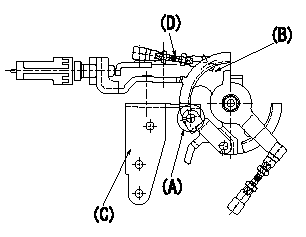
Side link lever adjustment
1. Fixing the side link lever
(1)Hold the control lever in the position a.
(2)Adjust the length of the connecting rod D so that a pin L1 can pass between the side link B and the actuator bracket C at A. Then fix.
2. Idle switch confirmation
Confirm that the switch is ON at the idle lever position.
3. Potentiometer confirmation (input voltage: V1)
Control lever:
(1)Idle position: V2 (checking point)
(2)Full position: V3 (adjusting point)
4. Confirming wire length
Accelerator wire
(1)Idle position: L2
(2)Idle~full stroke: L3
A/T wire:
(1)Idle position: L4
(2)Idle~full stroke: L5
----------
L1=Dia.5.8-0.2mm L2=161+-3mm L3=32.5+-3mm L4=-mm L5=-mm V1=10.00V V2=2.26+-0.7V V3=9.1+-0.03V a=0deg
----------
----------
L1=Dia.5.8-0.2mm L2=161+-3mm L3=32.5+-3mm L4=-mm L5=-mm V1=10.00V V2=2.26+-0.7V V3=9.1+-0.03V a=0deg
----------
0000001901 W-CSD ADJUSTMENT
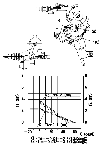
Adjustment of the W-CSD
1. Adjustment of the advance angle of the timer
(1)Determine the timer advance angle from the graph in Fig. 2.
(2)Adjust screw A so that the timer advance angle determined in item (1) is obtained.
2. Adjust dimension L.
Adjust using turnbuckle C so that the dimension L is as described on the figure 2.
C = control lever gap
D = timer stroke
Y1 = timer stroke TA
Y2 = control lever gap L
X = temperature t
----------
----------
----------
----------
Information:
Do not operate or work on this product unless you have read and understood the instruction and warnings in the relevant Operation and Maintenance Manuals and relevant service literature. Failure to follow the instructions or heed the warnings could result in injury or death. Proper care is your responsibility.
The following changes are adaptable to the products within the listed serial numbers, and are effective with all products after the listed serial numbers.The new and former DEF filter part numbers are listed in Table 1.
Table 1
Required Parts
Qty New Part Number Part Name Former Part Numbers(1)
1 584-8135 Diesel Exhaust Fluid Filter Gp 453-1604
1 584-8136 Diesel Exhaust Fluid Filter Gp 453-1605
1 584-8137 Diesel Exhaust Fluid Filter Gp 453-1606
(1) The former part number listed is for reference only and may differ.