Information injection-pump assembly
BOSCH
9 460 611 256
9460611256
ZEXEL
104749-0720
1047490720
Rating:
Components :
| 0. | INJECTION-PUMP ASSEMBLY | 104749-0720 |
| 1. | _ | |
| 2. | FUEL INJECTION PUMP | 104649-0720 |
| 3. | NUMBER PLATE | 146965-4000 |
| 4. | _ | 146672-6320 |
| 5. | CAPSULE | |
| 6. | ADJUSTING DEVICE | |
| 7. | NOZZLE AND HOLDER ASSY | 105140-1021 |
| 8. | Nozzle and Holder | RFG5 13 H50 |
| 9. | Open Pre:MPa(Kqf/cm2) | 13.2{135} |
| 10. | NOZZLE-HOLDER | 105071-1530 |
| 11. | NOZZLE | 105000-2240 |
Scheme ###:
| 1/6. | [1] | 146601-0700 | PACKING RING |
| 6. | [1] | 146100-0120 | SUPPLY PUMP |
| 9. | [1] | 146103-0000 | COVER |
| 10. | [2] | 139104-0000 | FLAT-HEAD SCREW |
| 12. | [1] | 146200-0320 | DRIVE SHAFT |
| 12/1. | [1] | 146200-0300 | DRIVE SHAFT |
| 12/2. | [1] | 146201-0000 | WOODRUFF KEY |
| 12/3. | [2] | 146202-0100 | DAMPER |
| 12/4. | [1] | 146203-0000 | TOOTHED GEAR |
| 17. | [1] | 146204-0000 | PLAIN WASHER |
| 20. | [1] | 146210-4220 | ROLLER SET |
| 24. | [1] | 146303-0000 | BEARING PIN |
| 25. | [1] | 146304-0000 | BEARING PIN |
| 26. | [1] | 146305-0000 | CLAMPING BAND |
| 27. | [1] | 146205-0000 | SLOTTED WASHER |
| 29. | [1] | 146220-3820 | CAM PLATE |
| 30. | [1] | 146600-0800 | O-RING |
| 31. | [1] | 146300-0500 | PUMP PLUNGER |
| 32. | [1] | 146301-0400 | SLIDING PIECE |
| 33. | [1] | 146603-0700 | SHIM D17.5&7.5T0.60 |
| 34. | [1] | 146302-3400 | COMPRESSION SPRING |
| 34B. | [1] | 146302-4200 | COMPRESSION SPRING |
| 35/1. | [0] | 146603-0700 | SHIM D17.5&7.5T0.60 |
| 35/1. | [0] | 146603-0800 | SHIM D17.5&7.5T0.70 |
| 35/1. | [0] | 146603-0900 | SHIM D17.5&7.5T0.90 |
| 35/1. | [0] | 146603-1000 | SHIM D17.5&7.5T1.00 |
| 35/1. | [0] | 146603-1100 | SHIM D17.5&7.5T1.20 |
| 35/1. | [0] | 146603-3600 | SHIM D17.5&7.5T2.40 |
| 36. | [1] | 146600-0800 | O-RING |
| 37. | [1] | 146310-0700 | COVER |
| 38. | [2] | 146620-5000 | BLEEDER SCREW |
| 39. | [1] | 146310-0100 | COVER |
| 40. | [2] | 146620-5000 | BLEEDER SCREW |
| 43. | [1] | 146230-0000 | SHIM |
| 44. | [1] | 146230-0100 | PLAIN WASHER |
| 45. | [1] | 146231-0001 | SLOTTED WASHER |
| 47. | [2] | 146233-0000 | SLOTTED WASHER |
| 48/1. | [1] | 146603-0000 | SHIM D17.0&5.2T0.50 |
| 48/1. | [1] | 146603-0100 | SHIM D17.0&5.2T0.80 |
| 48/1. | [1] | 146603-0200 | SHIM D17.0&5.2T1.00 |
| 48/1. | [1] | 146603-0300 | SHIM D17.0&5.2T1.20 |
| 48/1. | [1] | 146603-0400 | SHIM D17.0&5.2T1.50 |
| 48/1. | [1] | 146603-0500 | SHIM D17.0&5.2T1.80 |
| 48/1. | [1] | 146603-0600 | SHIM D17.0&5.2T2.00 |
| 48/1. | [1] | 146690-1400 | SHIM D17&5.2T0.9 |
| 48/1. | [1] | 146690-1500 | SHIM D17&5.2T1.1 |
| 48/1. | [1] | 146690-1600 | SHIM D17&5.2T1.3 |
| 48/1. | [1] | 146690-1700 | SHIM D17&5.2T1.4 |
| 48/1. | [1] | 146690-1800 | SHIM D17&5.2T1.6 |
| 48/1. | [1] | 146690-1900 | SHIM D17&5.2T1.7 |
| 48/1. | [1] | 146690-5800 | SHIM |
| 48/1. | [1] | 146690-5900 | SHIM |
| 48/1. | [1] | 146690-6000 | SHIM |
| 48/1. | [1] | 146690-6100 | SHIM |
| 48/1. | [1] | 146690-6200 | SHIM |
| 48/1. | [1] | 146690-6300 | SHIM |
| 48/1. | [1] | 146690-6400 | SHIM |
| 48/1. | [1] | 146690-6500 | SHIM |
| 48/1. | [1] | 146690-6600 | SHIM |
| 48/1. | [1] | 146690-6700 | SHIM |
| 48/1. | [1] | 146690-6800 | SHIM |
| 48/1. | [1] | 146690-6900 | SHIM |
| 48/1. | [1] | 146690-7000 | SHIM |
| 48/1. | [1] | 146690-7100 | SHIM |
| 48/1. | [1] | 146690-7200 | SHIM |
| 48/1. | [1] | 146690-7300 | SHIM |
| 48/1. | [1] | 146690-7400 | SHIM |
| 48/1. | [1] | 146690-7500 | SHIM |
| 48/1. | [1] | 146690-7800 | SHIM |
| 49. | [2] | 146234-0020 | GUIDE PIN |
| 50. | [1] | 146403-1120 | HYDRAULIC HEAD |
| 50. | [1] | 146403-1120 | HYDRAULIC HEAD |
| 50. | [1] | 146403-1120 | HYDRAULIC HEAD |
| 51. | [1] | 146600-0000 | O-RING |
| 52/1. | [1] | 146420-0000 | SHIM D9.5&3.0T1.90 |
| 52/1. | [1] | 146420-0100 | SHIM D9.5&3.0T1.92 |
| 52/1. | [1] | 146420-0200 | SHIM D9.5&3.0T1.94 |
| 52/1. | [1] | 146420-0300 | SHIM D9.5&3.0T1.96 |
| 52/1. | [1] | 146420-0400 | SHIM D9.5&3.0T1.98 |
| 52/1. | [1] | 146420-0500 | SHIM D9.5&3.0T2.00 |
| 52/1. | [1] | 146420-0600 | SHIM D9.5&3.0T2.02 |
| 52/1. | [1] | 146420-0700 | SHIM D9.5&3.0T2.04 |
| 52/1. | [1] | 146420-0800 | SHIM D9.5&3.0T2.06 |
| 52/1. | [1] | 146420-0900 | SHIM D9.5&3.0T2.08 |
| 52/1. | [1] | 146420-1000 | SHIM D9.5&3.0T2.10 |
| 52/1. | [1] | 146420-1100 | SHIM D9.5&3.0T2.12 |
| 52/1. | [1] | 146420-1200 | SHIM D9.5&3.0T2.14 |
| 52/1. | [1] | 146420-1300 | SHIM D9.5&3.0T2.16 |
| 52/1. | [1] | 146420-1400 | SHIM D9.5&3.0T2.18 |
| 52/1. | [1] | 146420-1500 | SHIM D9.5&3.0T2.20 |
| 52/1. | [1] | 146420-1600 | SHIM D9.5&3.0T2.22 |
| 52/1. | [1] | 146420-1700 | SHIM D9.5&3.0T2.24 |
| 52/1. | [1] | 146420-1800 | SHIM D9.5&3.0T2.26 |
| 52/1. | [1] | 146420-1900 | SHIM D9.5&3.0T2.28 |
| 52/1. | [1] | 146420-2000 | SHIM D9.5&3.0T2.30 |
| 52/1. | [1] | 146420-2100 | SHIM D9.5&3.0T2.32 |
| 52/1. | [1] | 146420-2200 | SHIM D9.5&3.0T2.34 |
| 52/1. | [1] | 146420-2300 | SHIM D9.5&3.0T2.36 |
| 52/1. | [1] | 146420-2400 | SHIM D9.5&3.0T2.38 |
| 52/1. | [1] | 146420-2500 | SHIM D9.5&3.0T2.40 |
| 52/1. | [1] | 146420-2600 | SHIM D9.5&3.0T2.42 |
| 52/1. | [1] | 146420-2700 | SHIM D9.5&3.0T2.44 |
| 52/1. | [1] | 146420-2800 | SHIM D9.5&3.0T2.46 |
| 52/1. | [1] | 146420-2900 | SHIM D9.5&3.0T2.48 |
| 52/1. | [1] | 146420-3000 | SHIM D9.5&3.0T2.50 |
| 52/1. | [1] | 146420-3100 | SHIM D9.5&3.0T2.52 |
| 52/1. | [1] | 146420-3200 | SHIM D9.5&3.0T2.54 |
| 52/1. | [1] | 146420-3300 | SHIM D9.5&3.0T2.56 |
| 52/1. | [1] | 146420-3400 | SHIM D9.5&3.0T2.58 |
| 52/1. | [1] | 146420-3500 | SHIM D9.5&3.0T2.60 |
| 52/1. | [1] | 146420-3600 | SHIM D9.5&3.0T2.62 |
| 52/1. | [1] | 146420-3700 | SHIM D9.5&3.0T2.64 |
| 52/1. | [1] | 146420-3800 | SHIM D9.5&3.0T2.66 |
| 52/1. | [1] | 146420-3900 | SHIM D9.5&3.0T2.68 |
| 52/1. | [1] | 146420-4000 | SHIM D9.5&3.0T2.70 |
| 52/1. | [1] | 146420-4100 | SHIM D9.5&3.0T2.72 |
| 52/1. | [1] | 146420-4200 | SHIM D9.5&3.0T2.74 |
| 52/1. | [1] | 146420-4300 | SHIM D9.5&3.0T2.76 |
| 52/1. | [1] | 146420-4400 | SHIM D9.5&3.0T2.78 |
| 52/1. | [1] | 146420-4500 | SHIM D9.5&3.0T2.80 |
| 52/1. | [1] | 146420-4600 | SHIM D9.5&3.0T2.82 |
| 52/1. | [1] | 146420-4700 | SHIM D9.5&3.0T2.84 |
| 52/1. | [1] | 146420-4800 | SHIM D9.5&3.0T2.86 |
| 52/1. | [1] | 146420-4900 | SHIM D9.5&3.0T2.88 |
| 52/1. | [1] | 146420-5000 | SHIM D9.5&3.0T2.90 |
| 52/1. | [1] | 146420-5100 | SHIM D9.5&3.0T1.74 |
| 52/1. | [1] | 146420-5200 | SHIM D9.5&3.0T1.76 |
| 52/1. | [1] | 146420-5300 | SHIM D9.5&3.0T1.78 |
| 52/1. | [1] | 146420-5400 | SHIM D9.5&3.0T1.80 |
| 52/1. | [1] | 146420-5500 | SHIM D9.5&3.0T1.82 |
| 52/1. | [1] | 146420-5600 | SHIM D9.5&3.0T1.84 |
| 52/1. | [1] | 146420-5700 | SHIM D9.5&3.0T1.86 |
| 52/1. | [1] | 146420-5800 | SHIM D9.5&3.0T1.88 |
| 54. | [4] | 146433-0100 | GASKET D12&6.4T1.00 |
| 55. | [4] | 146430-2420 | DELIVERY-VALVE ASSEMBLY |
| 56. | [4] | 146432-0000 | COMPRESSION SPRING |
| 58. | [4] | 146440-0220 | FITTING |
| 60. | [3] | 139106-0100 | FLAT-HEAD SCREW |
| 66. | [1] | 146600-0100 | O-RING |
| 67. | [1] | 146760-0920 | MANIFOLD-PRESSURE COMP. |
| 67/1. | [1] | 146805-2020 | GOVERNOR COVER |
| 67/14. | [1] | 146621-1700 | UNION NUT |
| 67/16. | [1] | 146526-3000 | BLEEDER SCREW |
| 67/23. | [1] | 146932-6420 | BRACKET |
| 67/31. | [1] | 146710-0800 | BUSHING |
| 67/32. | [1] | 146711-0000 | PLATE |
| 67/33. | [1] | 139218-0400 | UNION NUT |
| 67/34. | [1] | 146712-0700 | BEARING PIN |
| 67/35. | [1] | 146621-0300 | UNION NUT |
| 67/36. | [1] | 146600-1400 | O-RING |
| 67/37. | [1] | 146710-0100 | BUSHING |
| 67/38. | [1] | 139506-0200 | GASKET D8.9&6.8T1.00 |
| 67/39. | [1] | 146620-0300 | CAPSULE |
| 67/40. | [1] | 026512-1540 | GASKET D15.4&12.2T1.50 |
| 67/41. | [1] | 146713-4100 | ADJUSTING PIN |
| 67/42. | [2] | 146714-0000 | PLATE |
| 67/43. | [1] | 146715-0000 | DIAPHRAGM |
| 67/44. | [1] | 139306-0100 | LOCKING WASHER |
| 67/45. | [1] | 013030-6040 | UNION NUT M6P1H3.6 |
| 67/46. | [1] | 146716-0000 | UNION NUT |
| 67/47. | [1] | 146717-1100 | COILED SPRING |
| 67/48/1. | [1] | 146720-0000 | SPACER BUSHING L3.7 |
| 67/48/1. | [1] | 146720-0100 | SPACER BUSHING L3.9 |
| 67/48/1. | [1] | 146720-0200 | SPACER BUSHING L4.1 |
| 67/48/1. | [1] | 146720-0300 | SPACER BUSHING L4.3 |
| 67/48/1. | [1] | 146720-0400 | SPACER BUSHING L4.5 |
| 67/48/1. | [1] | 146720-0500 | SPACER BUSHING L4.7 |
| 67/48/1. | [1] | 146720-0600 | SPACER BUSHING L4.9 |
| 67/48/1. | [1] | 146720-0700 | SPACER BUSHING L5.1 |
| 67/48/1. | [1] | 146720-0800 | SPACER BUSHING L5.3 |
| 67/48/1. | [1] | 146720-0900 | SPACER BUSHING L2.7 |
| 67/48/1. | [1] | 146720-1000 | SPACER BUSHING L2.9 |
| 67/48/1. | [1] | 146720-1100 | SPACER BUSHING L3.1 |
| 67/48/1. | [1] | 146720-1200 | SPACER BUSHING L3.3 |
| 67/48/1. | [1] | 146720-1300 | SPACER BUSHING L3.5 |
| 67/48/1. | [1] | 146720-1400 | SPACER BUSHING L2.8 |
| 67/48/1. | [1] | 146720-1500 | SPACER BUSHING L3.0 |
| 67/48/1. | [1] | 146720-1600 | SPACER BUSHING L3.2 |
| 67/48/1. | [1] | 146720-1700 | SPACER BUSHING L3.4 |
| 67/48/1. | [1] | 146720-1800 | SPACER BUSHING L3.6 |
| 67/48/1. | [1] | 146720-1900 | SPACER BUSHING L3.8 |
| 67/48/1. | [1] | 146720-2000 | SPACER BUSHING L4.0 |
| 67/48/1. | [1] | 146720-2100 | SPACER BUSHING L4.2 |
| 67/48/1. | [1] | 146720-2200 | SPACER BUSHING L4.4 |
| 67/48/1. | [1] | 146720-2300 | SPACER BUSHING L4.6 |
| 67/48/1. | [1] | 146720-2400 | SPACER BUSHING L4.8 |
| 67/48/1. | [1] | 146720-2500 | SPACER BUSHING L5.0 |
| 67/48/1. | [1] | 146720-2600 | SPACER BUSHING L5.2 |
| 67/48/1. | [1] | 146720-2700 | SPACER BUSHING L5.4 |
| 67/48/1. | [1] | 146720-2800 | SPACER BUSHING L5.5 |
| 67/48/1. | [1] | 146720-2900 | SPACER BUSHING L5.6 |
| 67/48/1. | [1] | 146720-4500 | SPACER BUSHING L1.8 |
| 67/48/1. | [1] | 146720-4600 | SPACER BUSHING L1.9 |
| 67/48/1. | [1] | 146720-4700 | SPACER BUSHING L2.0 |
| 67/48/1. | [1] | 146720-4800 | SPACER BUSHING L2.1 |
| 67/48/1. | [1] | 146720-4900 | SPACER BUSHING L2.2 |
| 67/48/1. | [1] | 146720-5000 | SPACER BUSHING L2.3 |
| 67/48/1. | [1] | 146720-5100 | SPACER BUSHING L2.4 |
| 67/48/1. | [1] | 146720-5200 | SPACER BUSHING L2.5 |
| 67/48/1. | [1] | 146720-5300 | SPACER BUSHING L2.6 |
| 67/48/1. | [1] | 146725-2500 | SPACER BUSHING L5.7 |
| 67/48/1. | [1] | 146725-2600 | SPACER BUSHING L5.8 |
| 67/48/1. | [1] | 146725-2700 | SPACER BUSHING L5.9 |
| 67/48/1. | [1] | 146725-2800 | SPACER BUSHING L6.0 |
| 67/48/1. | [1] | 146725-2900 | SPACER BUSHING L6.1 |
| 67/48/1. | [1] | 146725-3000 | SPACER BUSHING L6.2 |
| 67/48/1. | [1] | 146725-3100 | SPACER BUSHING L6.3 |
| 67/48/1. | [1] | 146725-3200 | SPACER BUSHING L6.4 |
| 67/48/1. | [1] | 146725-3300 | SPACER BUSHING L6.5 |
| 67/48/1. | [1] | 146725-3400 | SPACER BUSHING L6.6 |
| 67/48/1. | [1] | 146725-3500 | SPACER BUSHING L6.7 |
| 67/48/1. | [1] | 146725-3600 | SPACER BUSHING L6.8 |
| 67/48/1. | [1] | 146725-3700 | SPACER BUSHING L6.9 |
| 67/48/1. | [1] | 146725-3800 | SPACER BUSHING L7.0 |
| 67/48/1. | [1] | 146725-3900 | SPACER BUSHING L7.1 |
| 67/48/1. | [1] | 146725-4000 | SPACER BUSHING L7.2 |
| 67/48/1. | [1] | 146725-4100 | SPACER BUSHING L7.3 |
| 67/48/1. | [1] | 146725-4200 | SPACER BUSHING L7.4 |
| 67/48/1. | [1] | 146725-4300 | SPACER BUSHING L7.5 |
| 67/49. | [1] | 146721-2120 | COVER |
| 67/54. | [2] | 146620-6100 | BLEEDER SCREW |
| 67/55. | [2] | 139006-4500 | BLEEDER SCREW |
| 67/56. | [1] | 146723-0300 | CONTROL LEVER |
| 67/57. | [1] | 146712-0100 | BEARING PIN |
| 67/58. | [2] | 146620-0600 | CAPSULE |
| 67/59. | [2] | 026506-1040 | GASKET D9.9&6.2T1 |
| 67/60. | [1] | 146724-0300 | ELEMENT |
| 67/61. | [1] | 146724-0600 | CAPSULE |
| 67/78. | [1] | 146600-4400 | SEAL RING |
| 67/99. | [2] | 010006-0870 | BLEEDER SCREW M6P1L8 7T |
| 67/100. | [1] | 146930-3100 | BRACKET |
| 67/102. | [1] | 146649-2200 | SPACER BUSHING |
| 67/112. | [1] | 146930-2100 | BRACKET |
| 67/200. | [1] | 139308-0300 | PLAIN WASHER |
| 67/201. | [1] | 146545-4100 | THREADED PIN |
| 67/201B. | [1] | 146545-4200 | THREADED PIN |
| 67/201C. | [1] | 146545-4300 | THREADED PIN |
| 67/202. | [1] | 139208-0900 | UNION NUT |
| 67/203. | [1] | 146600-1200 | O-RING |
| 68. | [1] | 146514-4320 | CONTROL SHAFT |
| 69. | [1] | 139310-0200 | PLAIN WASHER |
| 72. | [1] | 146830-1320 | CONTROL LEVER |
| 72B. | [1] | 146830-1420 | CONTROL LEVER |
| 72C. | [1] | 146830-2920 | CONTROL LEVER |
| 72D. | [1] | 146830-3020 | CONTROL LEVER |
| 73. | [1] | 014110-6440 | LOCKING WASHER |
| 75. | [1] | 146621-0700 | UNION NUT |
| 80. | [1] | 146548-0020 | CONTROL LEVER |
| 81. | [1] | 146549-7400 | SPACER BUSHING |
| 85. | [1] | 146549-7520 | RACK |
| 86. | [1] | 146549-4121 | RACK |
| 95. | [1] | 146551-8020 | FULCRUM LEVER |
| 104. | [2] | 146568-0000 | SLOTTED SPRING PIN |
| 105. | [2] | 026508-1140 | GASKET D11.4&8.2T1 |
| 106. | [2] | 146588-0500 | COILED SPRING |
| 107. | [1] | 146569-0300 | UNION NUT |
| 108. | [1] | 146570-0420 | GOVERNOR SHAFT |
| 109. | [1] | 146600-0400 | O-RING |
| 110/1. | [1] | 146571-0000 | SHIM D20.2&8.3T1.05 |
| 110/1. | [1] | 146571-0100 | SHIM D20.2&8.3T1.25 |
| 110/1. | [1] | 146571-0200 | SHIM D20.2&8.3T1.45 |
| 110/1. | [1] | 146571-0300 | SHIM D20.2&8.3T1.65 |
| 110/1. | [1] | 146571-0400 | SHIM D20.2&8.3T1.85 |
| 110/1. | [1] | 146571-0500 | SHIM D20.2&8.3T1.15 |
| 110/1. | [1] | 146571-0600 | SHIM D20.2&8.3T1.35 |
| 110/1. | [1] | 146571-0700 | SHIM D20.2&8.3T1.55 |
| 110/1. | [1] | 146571-0800 | SHIM D20.2&8.3T1.75 |
| 111. | [1] | 146602-0600 | PLAIN WASHER D20&8.4T1.40 |
| 112. | [1] | 146572-0020 | FLYWEIGHT ASSEMBLY |
| 114. | [1] | 146602-0500 | PLAIN WASHER D17&6.4T1.60 |
| 115. | [1] | 146875-6000 | SLIDING SLEEVE |
| 116. | [1] | 146576-0200 | CAP |
| 117/1. | [1] | 146577-1800 | PLUG L2.10 |
| 117/1. | [1] | 146577-1900 | PLUG L2.30 |
| 117/1. | [1] | 146577-2000 | PLUG L2.50 |
| 117/1. | [1] | 146577-2100 | PLUG L2.70 |
| 117/1. | [1] | 146577-2200 | PLUG L2.90 |
| 117/1. | [1] | 146577-2300 | PLUG L3.10 |
| 117/1. | [1] | 146577-2400 | PLUG L3.30 |
| 117/1. | [1] | 146577-2500 | PLUG L3.50 |
| 117/1. | [1] | 146577-2600 | PLUG L3.70 |
| 117/1. | [1] | 146577-2700 | PLUG L3.90 |
| 117/1. | [1] | 146577-2800 | PLUG L4.10 |
| 117/1. | [1] | 146577-2900 | PLUG L4.30 |
| 117/1. | [1] | 146577-3000 | PLUG L4.50 |
| 117/1. | [1] | 146577-3100 | PLUG L4.70 |
| 117/1. | [1] | 146577-3200 | PLUG L4.90 |
| 117/1. | [1] | 146577-3300 | PLUG L5.10 |
| 117/1. | [1] | 146577-6700 | PLUG L2.2 |
| 117/1. | [1] | 146577-6800 | PLUG L2.4 |
| 117/1. | [1] | 146577-6900 | PLUG L2.6 |
| 117/1. | [1] | 146577-7000 | PLUG L2.8 |
| 117/1. | [1] | 146577-7100 | PLUG L3.0 |
| 117/1. | [1] | 146577-7200 | PLUG L3.2 |
| 117/1. | [1] | 146577-7300 | PLUG L3.4 |
| 117/1. | [1] | 146577-7400 | PLUG L3.6 |
| 117/1. | [1] | 146577-7500 | PLUG L3.8 |
| 117/1. | [1] | 146577-7600 | PLUG L4.0 |
| 117/1. | [1] | 146577-7700 | PLUG L4.2 |
| 117/1. | [1] | 146577-7800 | PLUG L4.4 |
| 117/1. | [1] | 146577-7900 | PLUG L4.6 |
| 117/1. | [1] | 146577-8000 | PLUG L4.8 |
| 117/1. | [1] | 146577-8100 | PLUG L5.0 |
| 117/1. | [1] | 146877-0000 | PLUG L5.2 |
| 117/1. | [1] | 146877-0100 | PLUG L5.3 |
| 117/1. | [1] | 146877-0200 | PLUG L5.4 |
| 117/1. | [1] | 146877-0300 | PLUG L5.5 |
| 117/1. | [1] | 146877-4700 | PLUG |
| 117/1. | [1] | 146877-4800 | PLUG |
| 117/1. | [1] | 146877-4900 | PLUG |
| 117/1. | [1] | 146877-5000 | PLUG |
| 123. | [4] | 146620-0500 | HEX-SOCKET-HEAD CAP SCREW |
| 130. | [1] | 146421-0020 | CAPSULE |
| 130/2. | [1] | 026508-1140 | GASKET D11.4&8.2T1 |
| 130/3. | [1] | 146422-0000 | BLEEDER SCREW |
| 130/4. | [1] | 146600-0500 | O-RING |
| 133. | [1] | 146600-0600 | O-RING |
| 134. | [1] | 146600-0700 | O-RING |
| 135. | [1] | 146110-0920 | CONTROL VALVE |
| 135/5. | [1] | 146114-0000 | SPRING WASHER |
| 136. | [1] | 146120-0920 | OVER FLOW VALVE |
| 137. | [2] | 139512-0500 | GASKET |
| 138. | [1] | 146666-6720 | INLET UNION |
| 200. | [1] | 146206-0100 | COILED SPRING |
| 205. | [1] | 029470-4030 | WOODRUFF KEY |
| 214. | [1] | 146542-1400 | BUSHING |
| 215. | [1] | 146542-1500 | BUSHING |
| 217. | [1] | 146542-5700 | SLOTTED WASHER |
| 218. | [1] | 146592-4500 | COILED SPRING |
| 219. | [1] | 146541-3000 | BUSHING |
| 220. | [1] | 146592-4900 | COILED SPRING |
| 221. | [1] | 146930-2720 | BRACKET |
| 236. | [1] | 139006-4800 | BLEEDER SCREW |
| 237. | [1] | 146620-0200 | HEX-SOCKET-HEAD CAP SCREW |
| 240. | [1] | 146650-4320 | PULLING ELECTROMAGNET |
| 240/8. | [1] | 146600-1700 | O-RING |
| 242. | [1] | 146662-5220 | WIRE |
| 243. | [1] | 146621-1000 | UNION NUT |
| 245. | [3] | 139512-0500 | GASKET |
| 246. | [1] | 139812-1900 | EYE BOLT |
| 247. | [1] | 146608-7020 | INLET UNION |
| 248. | [1] | 146614-0200 | SPACER BUSHING |
| 253. | [1] | 139006-4400 | BLEEDER SCREW |
| 275. | [1] | 146612-6421 | BRACKET |
| 276. | [2] | 010010-1640 | BLEEDER SCREW M10P1.5L16 4T |
| 280. | [1] | 146361-0922 | START ADVANCE ASSY |
| 281. | [1] | 146600-0800 | O-RING |
| 282. | [2] | 139006-4700 | BLEEDER SCREW |
| 294. | [1] | 146665-8020 | INLET UNION |
| 800S. | [1] | 146019-4620 | PUMP HOUSING |
| 800S/1/6. | [1] | 146601-0700 | PACKING RING |
| 804S. | [1] | 146232-0220 | COMPRESSION SPRING |
| 805S. | [1] | 146574-0120 | PARTS SET |
| 810S. | [1] | 146600-2420 | REPAIR SET |
| 812S. | [1] | 146600-1920 | PARTS SET |
| 835S. | [1] | 146598-1000 | CAP |
| 836S/1. | [1] | 146598-0600 | CAP L18 |
| 836S/1. | [1] | 146598-0700 | CAP L21 |
| 836S/1. | [1] | 146598-0800 | CAP L24 |
| 836S/1. | [1] | 146598-0900 | CAP L27 |
| 890S. | [1] | 146949-0320 | LEVER GROUP |
| 903. | [1] | 146672-6320 | PULSE GENERATOR |
| 903/2. | [1] | 146600-1300 | O-RING &13W1.9 |
| 906. | [1] | 146965-4000 | NAMEPLATE |
Include in #2:
104749-0720
as INJECTION-PUMP ASSEMBLY
Cross reference number
BOSCH
9 460 611 256
9460611256
ZEXEL
104749-0720
1047490720
Zexel num
Bosch num
Firm num
Name
Calibration Data:
Adjustment conditions
Test oil
1404 Test oil ISO4113orSAEJ967d
1404 Test oil ISO4113orSAEJ967d
Test oil temperature
degC
45
45
50
Nozzle
105780-0060
Bosch type code
NP-DN0SD1510
Nozzle holder
105780-2150
Opening pressure
MPa
13
13
13.3
Opening pressure
kgf/cm2
133
133
136
Injection pipe
157805-7320
Injection pipe
Inside diameter - outside diameter - length (mm) mm 2-6-450
Inside diameter - outside diameter - length (mm) mm 2-6-450
Joint assembly
157641-4720
Tube assembly
157641-4020
Transfer pump pressure
kPa
20
20
20
Transfer pump pressure
kgf/cm2
0.2
0.2
0.2
Direction of rotation (viewed from drive side)
Right R
Right R
Injection timing adjustment
Pump speed
r/min
1000
1000
1000
Boost pressure
kPa
40
38.7
41.3
Boost pressure
kgf/cm2
0.41
0.396
0.424
Boost pressure
mmHg
300
290
310
Average injection quantity
mm3/st.
45.9
45.4
46.4
Difference in delivery
mm3/st.
3.5
Basic
*
Oil temperature
degC
50
48
52
Remarks
CBS
CBS
Injection timing adjustment_02
Pump speed
r/min
1000
1000
1000
Boost pressure
kPa
86.6
85.3
87.9
Boost pressure
kgf/cm2
0.88
0.866
0.894
Boost pressure
mmHg
650
640
660
Average injection quantity
mm3/st.
49.8
49.3
50.3
Difference in delivery
mm3/st.
4
Basic
*
Oil temperature
degC
50
48
52
Remarks
Full
Full
Injection timing adjustment_03
Pump speed
r/min
600
600
600
Boost pressure
kPa
46.7
45.4
48
Boost pressure
kgf/cm2
0.47
0.456
0.484
Boost pressure
mmHg
350
340
360
Average injection quantity
mm3/st.
42
39.5
44.5
Oil temperature
degC
50
48
52
Injection timing adjustment_04
Pump speed
r/min
1000
1000
1000
Boost pressure
kPa
0
0
0
Boost pressure
kgf/cm2
0
0
0
Boost pressure
mmHg
0
0
0
Average injection quantity
mm3/st.
38.6
36.1
41.1
Oil temperature
degC
50
48
52
Injection timing adjustment_05
Pump speed
r/min
1000
1000
1000
Boost pressure
kPa
40
38.7
41.3
Boost pressure
kgf/cm2
0.41
0.396
0.424
Boost pressure
mmHg
300
290
310
Average injection quantity
mm3/st.
45.9
44.9
46.9
Difference in delivery
mm3/st.
4
Oil temperature
degC
50
48
52
Injection timing adjustment_06
Pump speed
r/min
1000
1000
1000
Boost pressure
kPa
86.6
85.3
87.9
Boost pressure
kgf/cm2
0.88
0.866
0.894
Boost pressure
mmHg
650
640
660
Average injection quantity
mm3/st.
49.8
48.8
50.8
Difference in delivery
mm3/st.
4.5
Oil temperature
degC
50
48
52
Injection timing adjustment_07
Pump speed
r/min
2150
2150
2150
Boost pressure
kPa
86.6
85.3
87.9
Boost pressure
kgf/cm2
0.88
0.866
0.894
Boost pressure
mmHg
650
640
660
Average injection quantity
mm3/st.
41.5
39
44
Oil temperature
degC
52
50
54
Injection quantity adjustment
Pump speed
r/min
2250
2250
2250
Boost pressure
kPa
86.6
85.3
87.9
Boost pressure
kgf/cm2
0.88
0.866
0.894
Boost pressure
mmHg
650
640
660
Average injection quantity
mm3/st.
37
35
39
Basic
*
Oil temperature
degC
52
50
54
Injection quantity adjustment_02
Pump speed
r/min
2700
2700
2700
Boost pressure
kPa
86.6
85.3
87.9
Boost pressure
kgf/cm2
0.88
0.866
0.894
Boost pressure
mmHg
650
640
660
Average injection quantity
mm3/st.
3
Oil temperature
degC
55
53
57
Injection quantity adjustment_03
Pump speed
r/min
2250
2250
2250
Boost pressure
kPa
86.6
85.3
87.9
Boost pressure
kgf/cm2
0.88
0.866
0.894
Boost pressure
mmHg
650
640
660
Average injection quantity
mm3/st.
37
34.5
39.5
Oil temperature
degC
52
50
54
Injection quantity adjustment_04
Pump speed
r/min
2550
2550
2550
Boost pressure
kPa
86.6
85.3
87.9
Boost pressure
kgf/cm2
0.88
0.866
0.894
Boost pressure
mmHg
650
640
660
Average injection quantity
mm3/st.
10
7.5
12.5
Oil temperature
degC
55
52
58
Governor adjustment
Pump speed
r/min
360
360
360
Boost pressure
kPa
0
0
0
Boost pressure
kgf/cm2
0
0
0
Boost pressure
mmHg
0
0
0
Average injection quantity
mm3/st.
10.2
9.2
11.2
Difference in delivery
mm3/st.
2
Basic
*
Oil temperature
degC
48
46
50
Governor adjustment_02
Pump speed
r/min
360
360
360
Boost pressure
kPa
0
0
0
Boost pressure
kgf/cm2
0
0
0
Boost pressure
mmHg
0
0
0
Average injection quantity
mm3/st.
10.2
8.7
11.7
Difference in delivery
mm3/st.
2.5
Oil temperature
degC
48
46
50
Timer adjustment
Pump speed
r/min
100
100
100
Boost pressure
kPa
0
0
0
Boost pressure
kgf/cm2
0
0
0
Boost pressure
mmHg
0
0
0
Average injection quantity
mm3/st.
56
56
Basic
*
Oil temperature
degC
48
46
50
Remarks
Full
Full
Timer adjustment_02
Pump speed
r/min
100
100
100
Boost pressure
kPa
0
0
0
Boost pressure
kgf/cm2
0
0
0
Boost pressure
mmHg
0
0
0
Average injection quantity
mm3/st.
56
56
Oil temperature
degC
48
46
50
Speed control lever angle
Pump speed
r/min
360
360
360
Boost pressure
kPa
0
0
0
Boost pressure
kgf/cm2
0
0
0
Boost pressure
mmHg
0
0
0
Average injection quantity
mm3/st.
0
0
0
Oil temperature
degC
48
46
50
Remarks
Magnet OFF at idling position
Magnet OFF at idling position
0000000901
Pump speed
r/min
1000
1000
1000
Boost pressure
kPa
86.6
85.3
87.9
Boost pressure
kgf/cm2
0.88
0.866
0.894
Boost pressure
mmHg
650
640
660
Overflow quantity
cm3/min
380
250
510
Oil temperature
degC
50
48
52
Stop lever angle
Pump speed
r/min
1500
1500
1500
Boost pressure
kPa
86.6
85.3
87.9
Boost pressure
kgf/cm2
0.88
0.866
0.894
Boost pressure
mmHg
650
640
660
Pressure
kPa
539
510
568
Pressure
kgf/cm2
5.5
5.2
5.8
Basic
*
Oil temperature
degC
50
48
52
Stop lever angle_02
Pump speed
r/min
750
750
750
Boost pressure
kPa
86.6
85.3
87.9
Boost pressure
kgf/cm2
0.88
0.866
0.894
Boost pressure
mmHg
650
640
660
Pressure
kPa
324
285
363
Pressure
kgf/cm2
3.3
2.9
3.7
Oil temperature
degC
50
48
52
Stop lever angle_03
Pump speed
r/min
1500
1500
1500
Boost pressure
kPa
86.6
85.3
87.9
Boost pressure
kgf/cm2
0.88
0.866
0.894
Boost pressure
mmHg
650
640
660
Pressure
kPa
539
500
578
Pressure
kgf/cm2
5.5
5.1
5.9
Oil temperature
degC
50
48
52
Stop lever angle_04
Pump speed
r/min
2150
2150
2150
Boost pressure
kPa
86.6
85.3
87.9
Boost pressure
kgf/cm2
0.88
0.866
0.894
Boost pressure
mmHg
650
640
660
Pressure
kPa
696
657
735
Pressure
kgf/cm2
7.1
6.7
7.5
Oil temperature
degC
52
50
54
0000001101
Pump speed
r/min
1500
1500
1500
Boost pressure
kPa
86.6
85.3
87.9
Boost pressure
kgf/cm2
0.88
0.866
0.894
Boost pressure
mmHg
650
640
660
Timer stroke
mm
4.6
4.4
4.8
Basic
*
Oil temperature
degC
50
48
52
_02
Pump speed
r/min
750
750
750
Boost pressure
kPa
86.6
85.3
87.9
Boost pressure
kgf/cm2
0.88
0.866
0.894
Boost pressure
mmHg
650
640
660
Timer stroke
mm
0.5
0.1
1.3
Oil temperature
degC
50
48
52
_03
Pump speed
r/min
1500
1500
1500
Boost pressure
kPa
86.6
85.3
87.9
Boost pressure
kgf/cm2
0.88
0.866
0.894
Boost pressure
mmHg
650
640
660
Timer stroke
mm
4.6
4.2
5
Oil temperature
degC
50
48
52
_04
Pump speed
r/min
2150
2150
2150
Boost pressure
kPa
86.6
85.3
87.9
Boost pressure
kgf/cm2
0.88
0.866
0.894
Boost pressure
mmHg
650
640
660
Timer stroke
mm
7.4
6.9
8
Oil temperature
degC
52
50
54
0000001201
Max. applied voltage
V
8
8
8
Test voltage
V
13
12
14
0000001401
Pump speed
r/min
1500
1500
1500
Boost pressure
kPa
86.6
85.3
87.9
Boost pressure
kgf/cm2
0.88
0.866
0.894
Boost pressure
mmHg
650
640
660
Average injection quantity
mm3/st.
32.3
31.3
33.3
Timer stroke TA
mm
4.2
4.2
4.2
Timer stroke variation dT
mm
0.4
0.2
0.6
Basic
*
Oil temperature
degC
50
48
52
_02
Pump speed
r/min
1500
1500
1500
Boost pressure
kPa
86.6
85.3
87.9
Boost pressure
kgf/cm2
0.88
0.866
0.894
Boost pressure
mmHg
650
640
660
Average injection quantity
mm3/st.
32.3
30.8
33.8
Timer stroke variation dT
mm
0.4
0
0.8
Oil temperature
degC
50
48
52
_03
Pump speed
r/min
1500
1500
1500
Boost pressure
kPa
86.6
85.3
87.9
Boost pressure
kgf/cm2
0.88
0.866
0.894
Boost pressure
mmHg
650
640
660
Average injection quantity
mm3/st.
27.3
25.8
28.8
Timer stroke variation dT
mm
0.8
0.3
1.3
Oil temperature
degC
50
48
52
Timing setting
K dimension
mm
3.3
3.2
3.4
KF dimension
mm
5.8
5.7
5.9
MS dimension
mm
1.7
1.6
1.8
BCS stroke
mm
4
3.8
4.2
Pre-stroke
mm
0.3
0.28
0.32
Control lever angle alpha
deg.
25
21
29
Control lever angle beta
deg.
41
38
44
Test data Ex:
0000001801 SIDE LINK LEVER ADJUSTMENT
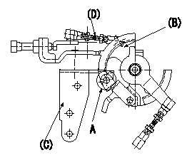
Side link lever adjustment
1. Adjusting the side link lever
(1)Hold the control lever in the position a.
(2)Adjust the length of the rod D so that a pin L1 can pass between the side link B and the actuator bracket C at A, then fix.
Wire length confirmation
Accelerator wire
(1)Idle position: L2
(2)Idle~full: L3
----------
a=0deg L1=Dia.5.8-0.2mm L2=161+-3mm L3=34.0+-4mm
----------
----------
a=0deg L1=Dia.5.8-0.2mm L2=161+-3mm L3=34.0+-4mm
----------
0000001901 W-CSD ADJUSTMENT
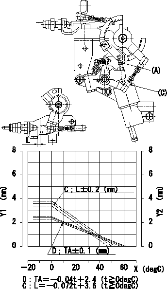
Adjustment of the W-CSD
1. Adjustment of the advance angle of the timer
(1)Determine the timer advance angle from the graph in Fig. 2.
(2)Adjust screw A so that the timer advance angle determined in item (1) is obtained.
2. Adjust dimension L.
Adjust using turnbuckle C so that the dimension L is as described on the figure 2.
C = control lever gap
D = timer stroke
Y1 = timer stroke TA
Y2 = control lever gap L
X = temperature t
----------
----------
----------
----------
Information:
Important Safety Information
Illustration 1 g02139237Work safely. Most accidents that involve product operation, maintenance, and repair are caused by failure to observe basic safety rules or precautions. An accident can often be avoided by recognizing potentially hazardous situations before an accident occurs. A person must be alert to potential hazards. This person should also have the necessary training, skills, and tools to perform these functions properly. Safety precautions and warnings are provided in this instruction and on the product. If these hazard warnings are not heeded, bodily injury or death could occur to you or to other persons. Caterpillar cannot anticipate every possible circumstance that might involve a potential hazard. Therefore, the warnings in this publication and the warnings that are on the product are not all inclusive. If a tool, a procedure, a work method, or operating technique that is not recommended by Caterpillar is used, ensure that it is safe for you and for other people to use. Ensure that the product will not be damaged or the product will not be made unsafe by the operation, lubrication, maintenance, or the repair procedures that are used.
Improper operation, lubrication, maintenance or repair of this product can be dangerous and could result in injury or death.Do not operate or perform any lubrication, maintenance or repair on this product, until you have read and understood the operation, lubrication, maintenance and repair information.
Safety precautions and warnings are provided in this manual and on the product. If these hazard warnings are not heeded, bodily injury or death could occur to you or to other persons.The hazards are identified by the safety alert symbol which is followed by a signal word such as danger, warning, or caution. The "" safety alert symbol is shown below.
Illustration 2 g00008666This safety alert symbol means:Pay attention!Become alert!Your safety is involved.The message that appears under the safety alert symbol explains the hazard.Operations that may cause product damage are identified by "" labels on the product and in this publication.Caterpillar cannot anticipate every possible circumstance that might involve a potential hazard. The safety information in this document and the safety information on the machine are not all inclusive. Determine that the tools, procedures, work methods, and operating techniques are safe. Determine that the operation, lubrication, maintenance, and repair procedures will not damage the machine. Also, you must determine that the operation, lubrication, maintenance, and repair procedures will not make the machine unsafe.The information, the specifications, and the illustrations that exist in this guideline are based on information which was available at the time of publication. The specifications, torques, pressures, measurements, adjustments, illustrations, and other items can change at any time. These changes can affect the service that is given to the product. Obtain the complete, most current information before you start any job. Caterpillar dealers can supply the most current information.Summary
The information included in this guideline should serve as an aid in fuel injection pump housing test procedure.Service Letters and Technical Information Bulletins
The most recent Service Letters and Technical Information Bulletins