Information injection-pump assembly
ZEXEL
104749-0690
1047490690

Rating:
Cross reference number
ZEXEL
104749-0690
1047490690
Zexel num
Bosch num
Firm num
Name
104749-0690
INJECTION-PUMP ASSEMBLY
Calibration Data:
Adjustment conditions
Test oil
1404 Test oil ISO4113orSAEJ967d
1404 Test oil ISO4113orSAEJ967d
Test oil temperature
degC
45
45
50
Nozzle
105780-0060
Bosch type code
NP-DN0SD1510
Nozzle holder
105780-2150
Opening pressure
MPa
13
13
13.3
Opening pressure
kgf/cm2
133
133
136
Injection pipe
157805-7320
Injection pipe
Inside diameter - outside diameter - length (mm) mm 2-6-450
Inside diameter - outside diameter - length (mm) mm 2-6-450
Joint assembly
157641-4720
Tube assembly
157641-4020
Transfer pump pressure
kPa
20
20
20
Transfer pump pressure
kgf/cm2
0.2
0.2
0.2
Direction of rotation (viewed from drive side)
Right R
Right R
Injection timing adjustment
Pump speed
r/min
1250
1250
1250
Boost pressure
kPa
33.3
32
34.6
Boost pressure
mmHg
250
240
260
Average injection quantity
mm3/st.
43.3
42.8
43.8
Difference in delivery
mm3/st.
3.5
Basic
*
Oil temperature
degC
50
48
52
Remarks
CBS
CBS
Injection timing adjustment_02
Pump speed
r/min
1250
1250
1250
Boost pressure
kPa
69.3
68
70.6
Boost pressure
mmHg
520
510
530
Average injection quantity
mm3/st.
48.6
48.1
49.1
Difference in delivery
mm3/st.
4
Basic
*
Oil temperature
degC
50
48
52
Remarks
Full
Full
Injection timing adjustment_03
Pump speed
r/min
750
750
750
Boost pressure
kPa
33.3
32
34.6
Boost pressure
mmHg
250
240
260
Average injection quantity
mm3/st.
42.8
42.8
42.8
Oil temperature
degC
50
48
52
Injection timing adjustment_04
Pump speed
r/min
1250
1250
1250
Boost pressure
kPa
0
0
0
Boost pressure
mmHg
0
0
0
Average injection quantity
mm3/st.
36.7
36.7
36.7
Oil temperature
degC
50
48
52
Injection timing adjustment_05
Pump speed
r/min
1250
1250
1250
Boost pressure
kPa
33.3
32
34.6
Boost pressure
mmHg
250
240
260
Average injection quantity
mm3/st.
43.3
42.3
44.3
Difference in delivery
mm3/st.
4
Oil temperature
degC
50
48
52
Injection timing adjustment_06
Pump speed
r/min
1250
1250
1250
Boost pressure
kPa
69.3
68
70.6
Boost pressure
mmHg
520
510
530
Average injection quantity
mm3/st.
48.6
47.6
49.6
Difference in delivery
mm3/st.
4.5
Oil temperature
degC
50
48
52
Injection timing adjustment_07
Pump speed
r/min
2150
2150
2150
Boost pressure
kPa
69.3
68
70.6
Boost pressure
mmHg
520
510
530
Average injection quantity
mm3/st.
41.4
41.4
41.4
Oil temperature
degC
52
50
54
Injection quantity adjustment
Pump speed
r/min
2500
2500
2500
Boost pressure
kPa
69.3
68
70.6
Boost pressure
mmHg
520
510
530
Average injection quantity
mm3/st.
21.8
19.8
23.8
Basic
*
Oil temperature
degC
55
52
58
Injection quantity adjustment_02
Pump speed
r/min
2800
2800
2800
Boost pressure
kPa
69.3
68
70.6
Boost pressure
mmHg
520
510
530
Average injection quantity
mm3/st.
5
Oil temperature
degC
55
52
58
Injection quantity adjustment_03
Pump speed
r/min
2500
2500
2500
Boost pressure
kPa
69.3
68
70.6
Boost pressure
mmHg
520
510
530
Average injection quantity
mm3/st.
21.8
19.3
24.3
Oil temperature
degC
55
52
58
Governor adjustment
Pump speed
r/min
385
385
385
Boost pressure
kPa
0
0
0
Boost pressure
mmHg
0
0
0
Average injection quantity
mm3/st.
14.2
13.2
15.2
Difference in delivery
mm3/st.
2
Basic
*
Oil temperature
degC
48
46
50
Governor adjustment_02
Pump speed
r/min
385
385
385
Boost pressure
kPa
0
0
0
Boost pressure
mmHg
0
0
0
Average injection quantity
mm3/st.
14.2
12.7
15.7
Difference in delivery
mm3/st.
2.5
Oil temperature
degC
48
46
50
Timer adjustment
Pump speed
r/min
100
100
100
Boost pressure
kPa
0
0
0
Boost pressure
mmHg
0
0
0
Average injection quantity
mm3/st.
58
58
Basic
*
Oil temperature
degC
48
46
50
Remarks
Full
Full
Timer adjustment_02
Pump speed
r/min
100
100
100
Boost pressure
kPa
0
0
0
Boost pressure
mmHg
0
0
0
Average injection quantity
mm3/st.
58
58
Oil temperature
degC
48
46
50
Speed control lever angle
Pump speed
r/min
385
385
385
Boost pressure
kPa
0
0
0
Boost pressure
mmHg
0
0
0
Average injection quantity
mm3/st.
0
0
0
Oil temperature
degC
48
46
50
Remarks
Magnet OFF at idling position
Magnet OFF at idling position
0000000901
Pump speed
r/min
1000
1000
1000
Boost pressure
kPa
69.3
68
70.6
Boost pressure
mmHg
520
510
530
Overflow quantity
cm3/min
600
470
730
Oil temperature
degC
50
48
52
Stop lever angle
Pump speed
r/min
1000
1000
1000
Boost pressure
kPa
69.3
68
70.6
Boost pressure
mmHg
520
510
530
Pressure
kPa
618
589
647
Pressure
kgf/cm2
6.3
6
6.6
Basic
*
Oil temperature
degC
50
48
52
Stop lever angle_02
Pump speed
r/min
1000
1000
1000
Boost pressure
kPa
69.3
68
70.6
Boost pressure
mmHg
520
510
530
Pressure
kPa
618
579
657
Pressure
kgf/cm2
6.3
5.9
6.7
Oil temperature
degC
50
48
52
0000001101
Pump speed
r/min
1000
1000
1000
Boost pressure
kPa
69.3
68
70.6
Boost pressure
mmHg
520
510
530
TCV duty (%) F TCV 60Hz
%
100
100
100
Timer stroke
mm
10.6
10.4
10.8
Basic
*
Oil temperature
degC
50
48
52
_02
Pump speed
r/min
100
100
100
Boost pressure
kPa
69.3
68
70.6
Boost pressure
mmHg
520
510
530
TCV duty (%) F TCV 60Hz
%
100
100
100
Timer stroke
mm
3.5
3.5
3.5
Oil temperature
degC
48
46
50
_03
Pump speed
r/min
1000
1000
1000
Boost pressure
kPa
69.3
68
70.6
Boost pressure
mmHg
520
510
530
TCV duty (%) F TCV 60Hz
%
100
100
100
Timer stroke
mm
10.6
10.6
10.6
Oil temperature
degC
50
48
52
_04
Pump speed
r/min
2150
2150
2150
Boost pressure
kPa
69.3
68
70.6
Boost pressure
mmHg
520
510
530
TCV duty (%) F TCV 60Hz
%
100
100
100
Timer stroke
mm
11.4
11.4
11.4
Oil temperature
degC
52
50
54
0000001301
Max. applied voltage
V
8
8
8
Test voltage
V
13
12
14
0000002701
K dimension
mm
3.3
3.2
3.4
KF dimension
mm
5.8
5.7
5.9
MS dimension
mm
1.7
1.6
1.8
Control lever angle alpha
deg.
0
-4
4
Control lever angle beta
deg.
33.3
30.3
36.3
Test data Ex:
0000001901 TIMER PISTON SEVSOR ADJ
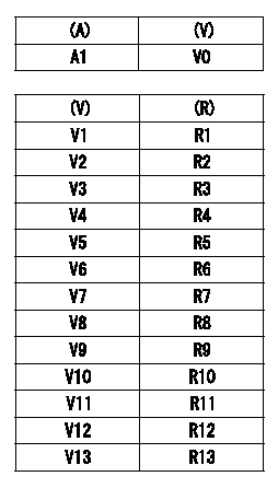
TPS (timer piston sensor) adjustment
Use the special circuit (corresponding to H) to measure TPS output voltage.
(1)Measure the TPS output voltage for zero compensation (no resistance).
(A): timer stroke TA
(V): compensation zero TPS output voltage (VTPS)
(2)Compensation resistor installation:
From the table, select and install a compensation resistor so that the compensation output voltage value is zero.
(R): selected compensation resistance
----------
H=479040-5600
----------
A1=0mm V0=0.510+-0.128V V1=0.382~0.401V V2=0.402~0.421V V3=0.422~0.440V V4=0.441~0.460V V5=0.461~0.479V V6=0.480~0.499V V7=0.500~0.519V V8=0.520~0.539V V9=0.540~0.558V V10=0.559~0.578V V11=0.579~0.597V V12=0.598~0.617V V13=0.618~0.637V R1=No.1,0.18kohm R2=No.2,0.30kohm R3=No.3,0.43kohm R4=No.4,0.62kohm R5=No.5,0.82kohm R6=No.6,1.10kohm R7=No.7,1.50kohm R8=No.8,2.00kohm R9=No.9,2.70kohm R10=No.10,3.90kohm R11=No.11,5.60kohm R12=No.12,8.20kohm R13=No.13,15.00kohm
----------
H=479040-5600
----------
A1=0mm V0=0.510+-0.128V V1=0.382~0.401V V2=0.402~0.421V V3=0.422~0.440V V4=0.441~0.460V V5=0.461~0.479V V6=0.480~0.499V V7=0.500~0.519V V8=0.520~0.539V V9=0.540~0.558V V10=0.559~0.578V V11=0.579~0.597V V12=0.598~0.617V V13=0.618~0.637V R1=No.1,0.18kohm R2=No.2,0.30kohm R3=No.3,0.43kohm R4=No.4,0.62kohm R5=No.5,0.82kohm R6=No.6,1.10kohm R7=No.7,1.50kohm R8=No.8,2.00kohm R9=No.9,2.70kohm R10=No.10,3.90kohm R11=No.11,5.60kohm R12=No.12,8.20kohm R13=No.13,15.00kohm
0000002001 POTENTIOMETER ADJUSTMENT
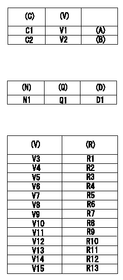
Adjustment of the potentiometer
(1)Potentiometer setting:
(A): Adjusting point
(B): Checking point
(C): Control lever opening
(V): P/N output voltage
(2)Dummy bolt setting:
Fix the control lever with the dummy bolt so that the injection quantity is as shown in the following table at the pump speed = N1.
(N): Speed of the pump
(Q): Injection quantity
(D): Targeted lever angle
C1:Full speed position
C2:Idling position
(3)Read the output voltage (V) of the potentiometer in the state indicated in (2) above. Then, select the compensation resistor from the following table and replace.
(R): Compensation resistance
Note
After replacing the compensation resistor, the output voltage is the potentiometer value when the special compensation circuit (control unit) is used.
Caution: The potentiometer output voltage is the voltage at the applied voltage Vi, and the control unit output voltage is the voltage at the applied voltage ViC.
----------
N1=1000r/min Vi=10V Vic=5V
----------
V1=8.4+-0.03V V2=(2.85+-0.7)V N1=1000r/min Q1=31.9+-1.0cm3/1000st D1=(14.3)deg V3=4.42~4.53V V4=4.54~4.65V V5=4.66~4.77V V6=4.78~4.89V V7=4.90~5.01V V8=5.02~5.13V V9=5.14~5.25V V10=5.26~5.37V V11=5.38~5.49V V12=5.50~5.61V V13=5.62~5.73V V14=5.74~5.85V V15=5.86~5.97V R1=No.1,0.18kohm R2=No.2,0.30kohm R3=No.3,0.43kohm R4=No.4,0.62kohm R5=No.5,0.82kohm R6=No.6,1.10kohm R7=No.7,1.50kohm R8=No.8,2.00kohm R9=No.9,2.70kohm R10=No.10,3.90kohm R11=No.11,5.60kohm R12=No.12,8.20kohm R13=No.13,15.00kohm
----------
N1=1000r/min Vi=10V Vic=5V
----------
V1=8.4+-0.03V V2=(2.85+-0.7)V N1=1000r/min Q1=31.9+-1.0cm3/1000st D1=(14.3)deg V3=4.42~4.53V V4=4.54~4.65V V5=4.66~4.77V V6=4.78~4.89V V7=4.90~5.01V V8=5.02~5.13V V9=5.14~5.25V V10=5.26~5.37V V11=5.38~5.49V V12=5.50~5.61V V13=5.62~5.73V V14=5.74~5.85V V15=5.86~5.97V R1=No.1,0.18kohm R2=No.2,0.30kohm R3=No.3,0.43kohm R4=No.4,0.62kohm R5=No.5,0.82kohm R6=No.6,1.10kohm R7=No.7,1.50kohm R8=No.8,2.00kohm R9=No.9,2.70kohm R10=No.10,3.90kohm R11=No.11,5.60kohm R12=No.12,8.20kohm R13=No.13,15.00kohm
0000002101 WIRE
Wire length confirmation
Accelerator wire: Idle-full stroke: L1
A/T wire: idle~full stroke: L2
Confirmation on the idle SW
Confirm that the switch is ON at the idle lever position.
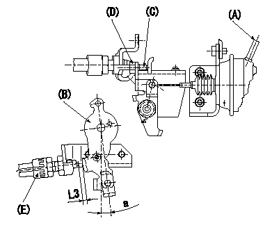
Adjustment of the double stage actuator:
(1)Apply negative pressure P1 {P2} to the actuator through the negative pressure inlet port.
(2)In status (1) above, adjust the screw C so that the control lever B position is a (ie, the distance between the control lever and the idle switch E is L3). Fix using nut D.
TT
(Reference) actuator stroke:
(1)First step: L4
(2)Second stage: L5
----------
L1=32.5+-3.5mm L2=28.4+-2mm L3=1.9+-0.5mm L4=6+-0.5mm L5=4.5mm a=5deg P1=-66.6kPa P2=-500mmHg T=6~9N-m{0.6~0.9kgf-m}
----------
L3=1.9+-0.5mm a=3.3deg
----------
L1=32.5+-3.5mm L2=28.4+-2mm L3=1.9+-0.5mm L4=6+-0.5mm L5=4.5mm a=5deg P1=-66.6kPa P2=-500mmHg T=6~9N-m{0.6~0.9kgf-m}
----------
L3=1.9+-0.5mm a=3.3deg
Information:
Reference
Refer to the electrical system schematic that is in the Electrical Schematic for the complete electrical system schematic of the engine. Refer to the Electronic Troubleshooting manual for additional information.Grounding Practices
Proper grounding for the vessel's electrical system and the engine electrical system is necessary for proper performance and reliability. Improper grounding will result in unreliable electrical circuit paths and in uncontrolled electrical circuit paths.Uncontrolled engine electrical circuit paths can result in damage to the main bearings, to the crankshaft bearing journal surfaces, and to the aluminum components.Uncontrolled electrical circuit paths can cause electrical noise which may degrade the vessel's performance and the radio performance.In order to ensure proper functioning of the vessel's electrical system and of the engine electrical system, an engine-to-frame ground strap with a direct path to the battery must be used. This is provided by a ground from the electric starting motor to the frame and to the negative battery post.The ground path must be capable of carrying any potential currents. A wire that is AWG 0 or more is recommended for the ground of the electric starting motor.The engine alternator should be grounded to the battery with a wire size that is capable of managing the full charging current of the alternator.
When jump starting an engine, the instructions in the Operation and Maintenance Manual, "Starting with Jump Start Cables" should be followed in order to properly start the engine.This engine may be equipped with a 12 volt starting system or with a 24 volt starting system. Only equal voltage for boost starting should be used. The use of a welder or of a higher voltage will damage the electrical system.
The engine has several input components which are electronic. These components require an operating voltage.This engine is tolerant of common external sources of electrical noise. Electromechanical buzzers can cause disruptions in the power supply. If electromechanical buzzers are used on the vessel, the engine electronics should be powered directly from the battery system through a dedicated relay. The engine electronics should not be powered through a common power bus with other devices that are activated by the keyswitch.Engine Electrical System
The electrical system can have three separate circuits. The three circuits are the charging circuit, the starting circuit, and the low amperage circuit. Some of the electrical system components are used in more than one circuit.The charging circuit is in operation when the engine is running. The charging circuit uses an alternator in order to create electricity. A voltage regulator in the circuit controls the electrical output in order to maintain the battery at full charge.The starting circuit is in operation when the start switch is activated.The low amperage circuit and the charging circuit are connected through the ammeter. The starting circuit is not connected through the ammeter.Starting System Components
Solenoid
Illustration 1 g00292316
Typical cross section of a solenoidA solenoid is an electromagnetic switch that performs two basic functions:
The solenoid closes the high current circuit for the electric starting motor with a low current start switch circuit.
The solenoid engages
Have questions with 104749-0690?
Group cross 104749-0690 ZEXEL
104749-0690
INJECTION-PUMP ASSEMBLY