Information injection-pump assembly
ZEXEL
104748-2460
1047482460
Rating:
Components :
| 0. | INJECTION-PUMP ASSEMBLY | 104748-2460 |
| 1. | _ | |
| 2. | FUEL INJECTION PUMP | |
| 3. | NUMBER PLATE | 146644-9300 |
| 4. | _ | 146672-1120 |
| 5. | CAPSULE | |
| 6. | ADJUSTING DEVICE | |
| 7. | NOZZLE AND HOLDER ASSY | 105141-2391 |
| 8. | Nozzle and Holder | 16600-16A25 |
| 9. | Open Pre:MPa(Kqf/cm2) | 12.7{130} |
| 10. | NOZZLE-HOLDER | 105071-1361 |
| 11. | NOZZLE | 105000-1760 |
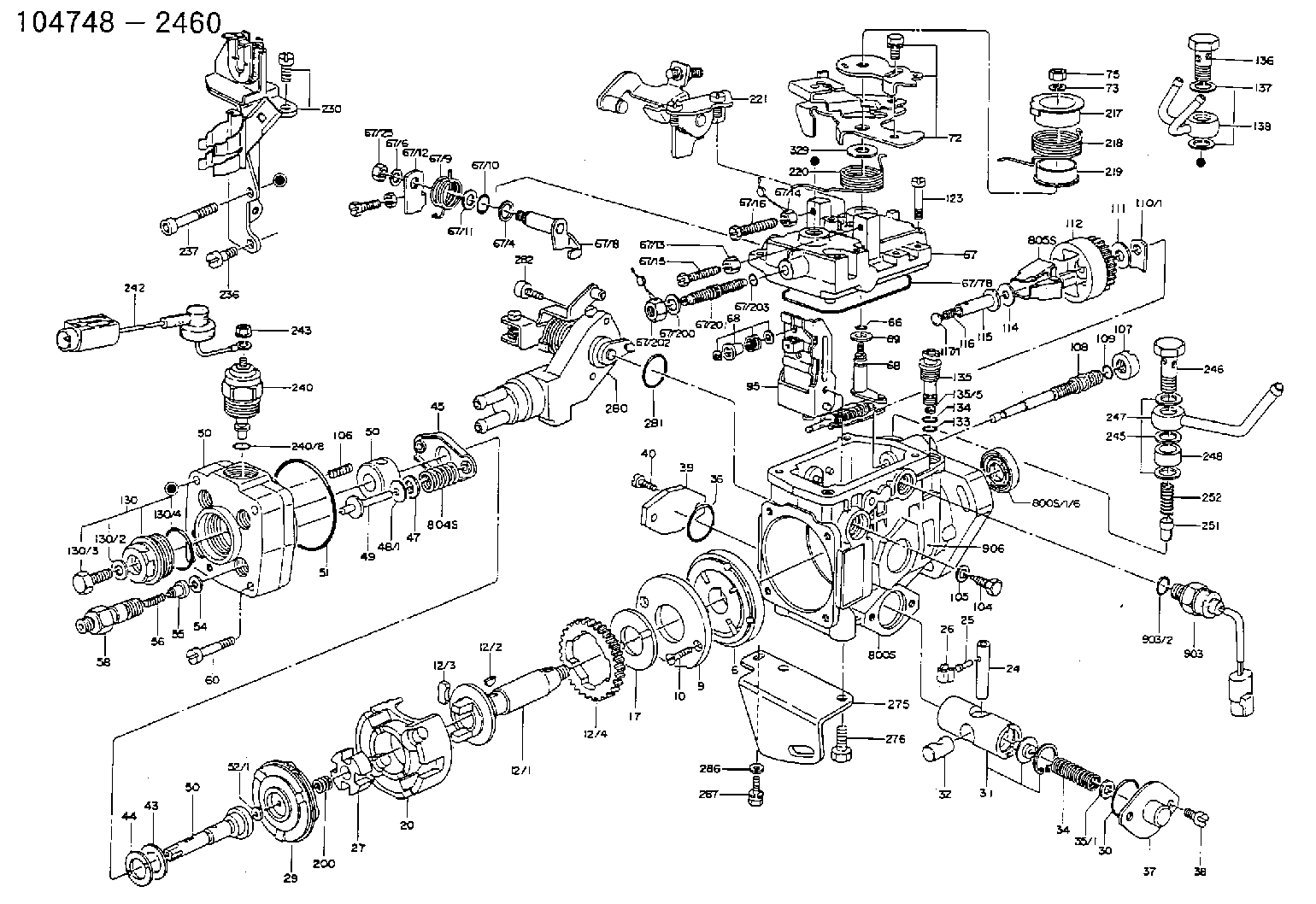
Scheme ###:
| 1/6. | [1] | 146601-0200 | PACKING RING |
| 6. | [1] | 146100-0320 | SUPPLY PUMP D17 SVT |
| 9. | [1] | 146103-0100 | COVER SVT |
| 10. | [2] | 139104-0000 | FLAT-HEAD SCREW |
| 12/1. | [1] | 146200-0000 | DRIVE SHAFT |
| 12/2. | [1] | 146201-0000 | WOODRUFF KEY |
| 12/3. | [2] | 146202-0100 | DAMPER |
| 12/4. | [1] | 146203-0000 | TOOTHED GEAR |
| 17. | [1] | 146204-0000 | PLAIN WASHER |
| 20. | [1] | 146210-2420 | ROLLER SET |
| 24. | [1] | 146303-0000 | BEARING PIN |
| 25. | [1] | 146304-0000 | BEARING PIN |
| 26. | [1] | 146305-0000 | CLAMPING BAND |
| 27. | [1] | 146205-0000 | SLOTTED WASHER |
| 29. | [1] | 146220-0120 | CAM PLATE '01'SK3255 |
| 30. | [1] | 146600-0800 | O-RING |
| 31. | [1] | 146311-4920 | PUMP PLUNGER SVT |
| 32. | [1] | 146301-0000 | SLIDING PIECE |
| 34. | [1] | 146312-0900 | COMPRESSION SPRING K=0.115 |
| 35/1. | [1] | 146603-8100 | SHIM NMC LD28 GY1 |
| 35/1. | [1] | 146603-8200 | SHIM NMC LD28 GY1 |
| 35/1. | [1] | 146603-8300 | SHIM NMC LD28 GY1 |
| 35/1. | [1] | 146603-8400 | SHIM NMC LD28 GY1 |
| 35/1. | [1] | 146603-8500 | SHIM NMC LD28 GY1 |
| 36. | [1] | 146600-0800 | O-RING |
| 37. | [1] | 146310-0600 | COVER NMC LD28 GY1 |
| 38. | [2] | 139106-0000 | FLAT-HEAD SCREW |
| 39. | [1] | 146310-0100 | COVER |
| 40. | [2] | 139106-0000 | FLAT-HEAD SCREW |
| 43. | [1] | 146230-0000 | SHIM |
| 44. | [1] | 146230-0100 | PLAIN WASHER |
| 45. | [1] | 146231-0000 | SLOTTED WASHER |
| 47. | [2] | 146233-0000 | SLOTTED WASHER |
| 48/1. | [1] | 146603-0000 | SHIM |
| 48/1. | [1] | 146603-0100 | SHIM |
| 48/1. | [1] | 146603-0200 | SHIM |
| 48/1. | [1] | 146603-0300 | SHIM |
| 48/1. | [1] | 146603-0400 | SHIM |
| 48/1. | [1] | 146603-0500 | SHIM |
| 48/1. | [1] | 146603-0600 | SHIM |
| 48/1. | [1] | 146690-1400 | SHIM |
| 48/1. | [1] | 146690-1500 | SHIM |
| 48/1. | [1] | 146690-1600 | SHIM |
| 48/1. | [1] | 146690-1700 | SHIM |
| 48/1. | [1] | 146690-1800 | SHIM |
| 48/1. | [1] | 146690-1900 | SHIM |
| 49. | [2] | 146234-0020 | GUIDE PIN |
| 50. | [1] | 146400-4220 | HYDRAULIC HEAD D8 2X1.2 A0.4 |
| 50. | [1] | 146400-4220 | HYDRAULIC HEAD D8 2X1.2 A0.4 |
| 50. | [1] | 146400-4220 | HYDRAULIC HEAD D8 2X1.2 A0.4 |
| 51. | [1] | 146600-0000 | O-RING |
| 52/1. | [1] | 146420-0000 | SHIM |
| 52/1. | [1] | 146420-0100 | SHIM |
| 52/1. | [1] | 146420-0200 | SHIM |
| 52/1. | [1] | 146420-0300 | SHIM |
| 52/1. | [1] | 146420-0400 | SHIM |
| 52/1. | [1] | 146420-0500 | SHIM |
| 52/1. | [1] | 146420-0600 | SHIM |
| 52/1. | [1] | 146420-0700 | SHIM |
| 52/1. | [1] | 146420-0800 | SHIM |
| 52/1. | [1] | 146420-0900 | SHIM |
| 52/1. | [1] | 146420-1000 | SHIM |
| 52/1. | [1] | 146420-1100 | SHIM |
| 52/1. | [1] | 146420-1200 | SHIM |
| 52/1. | [1] | 146420-1300 | SHIM |
| 52/1. | [1] | 146420-1400 | SHIM |
| 52/1. | [1] | 146420-1500 | SHIM |
| 52/1. | [1] | 146420-1600 | SHIM |
| 52/1. | [1] | 146420-1700 | SHIM |
| 52/1. | [1] | 146420-1800 | SHIM |
| 52/1. | [1] | 146420-1900 | SHIM |
| 52/1. | [1] | 146420-2000 | SHIM |
| 52/1. | [1] | 146420-2100 | SHIM |
| 52/1. | [1] | 146420-2200 | SHIM |
| 52/1. | [1] | 146420-2300 | SHIM |
| 52/1. | [1] | 146420-2400 | SHIM |
| 52/1. | [1] | 146420-2500 | SHIM |
| 52/1. | [1] | 146420-2600 | SHIM |
| 52/1. | [1] | 146420-2700 | SHIM |
| 52/1. | [1] | 146420-2800 | SHIM |
| 52/1. | [1] | 146420-2900 | SHIM |
| 52/1. | [1] | 146420-3000 | SHIM |
| 52/1. | [1] | 146420-3100 | SHIM |
| 52/1. | [1] | 146420-3200 | SHIM |
| 52/1. | [1] | 146420-3300 | SHIM |
| 52/1. | [1] | 146420-3400 | SHIM |
| 52/1. | [1] | 146420-3500 | SHIM |
| 52/1. | [1] | 146420-3600 | SHIM |
| 52/1. | [1] | 146420-3700 | SHIM |
| 52/1. | [1] | 146420-3800 | SHIM |
| 52/1. | [1] | 146420-3900 | SHIM |
| 52/1. | [1] | 146420-4000 | SHIM |
| 52/1. | [1] | 146420-4100 | SHIM |
| 52/1. | [1] | 146420-4200 | SHIM |
| 52/1. | [1] | 146420-4300 | SHIM |
| 52/1. | [1] | 146420-4400 | SHIM |
| 52/1. | [1] | 146420-4500 | SHIM |
| 52/1. | [1] | 146420-4600 | SHIM |
| 52/1. | [1] | 146420-4700 | SHIM |
| 52/1. | [1] | 146420-4800 | SHIM |
| 52/1. | [1] | 146420-4900 | SHIM |
| 52/1. | [1] | 146420-5000 | SHIM |
| 52/1. | [1] | 146420-5100 | SHIM |
| 52/1. | [1] | 146420-5200 | SHIM |
| 52/1. | [1] | 146420-5300 | SHIM |
| 52/1. | [1] | 146420-5400 | SHIM |
| 52/1. | [1] | 146420-5500 | SHIM |
| 52/1. | [1] | 146420-5600 | SHIM |
| 52/1. | [1] | 146420-5700 | SHIM |
| 52/1. | [1] | 146420-5800 | SHIM |
| 54. | [4] | 146433-0100 | GASKET |
| 55. | [4] | 146430-0120 | DELIVERY-VALVE ASSEMBLY 'VE2' VR25 |
| 56. | [4] | 146432-0000 | COMPRESSION SPRING K=0.48 |
| 58. | [4] | 146440-0220 | FITTING D0.45 L=50 |
| 60. | [3] | 139106-0100 | FLAT-HEAD SCREW |
| 66. | [1] | 146600-0100 | O-RING |
| 67. | [1] | 146502-8520 | GOVERNOR COVER CD17 XE |
| 67/1. | [1] | 146508-2820 | GOVERNOR COVER CD17 AUTO |
| 67/4. | [1] | 139310-0200 | PLAIN WASHER |
| 67/6. | [1] | 014110-6440 | LOCKING WASHER D12.2&6.1T1.5 |
| 67/8. | [1] | 146515-0020 | LEVER SHAFT |
| 67/9. | [1] | 146587-6700 | COILED SPRING CD17 AUTO |
| 67/10. | [1] | 146600-0200 | O-RING |
| 67/11. | [1] | 146602-0100 | PLAIN WASHER |
| 67/12. | [1] | 146540-3220 | CONTROL LEVER |
| 67/12B. | [1] | 146540-3320 | CONTROL LEVER ' 0' |
| 67/13. | [1] | 146621-1700 | UNION NUT |
| 67/14. | [1] | 146621-1800 | UNION NUT |
| 67/15. | [1] | 146526-3400 | BLEEDER SCREW |
| 67/16. | [1] | 146526-2900 | BLEEDER SCREW |
| 67/25. | [1] | 013020-6040 | UNION NUT |
| 67/78. | [1] | 146600-1000 | SEAL RING |
| 68. | [1] | 146510-8620 | CONTROL SHAFT R=13 W R |
| 68. | [1] | 146510-8620 | CONTROL SHAFT R=13 W R |
| 69. | [1] | 139310-0200 | PLAIN WASHER |
| 72. | [1] | 146537-2620 | CONTROL LEVER |
| 73. | [1] | 014110-6440 | LOCKING WASHER D12.2&6.1T1.5 |
| 75. | [1] | 013020-6040 | UNION NUT |
| 87. | [1] | 139308-0300 | PLAIN WASHER |
| 88. | [1] | 146545-0300 | THREADED PIN |
| 88B. | [1] | 146545-0400 | THREADED PIN |
| 88C. | [1] | 146545-0500 | THREADED PIN |
| 90. | [1] | 139208-0100 | UNION NUT |
| 91. | [1] | 146600-1200 | O-RING |
| 95. | [1] | 146551-4420 | FULCRUM LEVER I=2.2 |
| 104. | [2] | 146568-0000 | SLOTTED SPRING PIN |
| 105. | [2] | 026508-1140 | GASKET |
| 106. | [2] | 146588-0000 | COILED SPRING |
| 107. | [1] | 146569-0000 | UNION NUT |
| 108. | [1] | 146570-0420 | GOVERNOR SHAFT R-L/T |
| 109. | [1] | 146600-0400 | O-RING |
| 110/1. | [1] | 146571-0000 | SHIM |
| 110/1. | [1] | 146571-0100 | SHIM |
| 110/1. | [1] | 146571-0200 | SHIM |
| 110/1. | [1] | 146571-0300 | SHIM |
| 110/1. | [1] | 146571-0400 | SHIM |
| 110/1. | [1] | 146571-0500 | SHIM |
| 110/1. | [1] | 146571-0600 | SHIM |
| 110/1. | [1] | 146571-0700 | SHIM |
| 110/1. | [1] | 146571-0800 | SHIM |
| 111. | [1] | 146602-0600 | PLAIN WASHER |
| 112. | [1] | 146572-0020 | FLYWEIGHT ASSEMBLY |
| 114. | [1] | 146602-0500 | PLAIN WASHER |
| 115. | [1] | 146575-2300 | SLIDING SLEEVE '23' D0.5G2-0.3 |
| 116. | [1] | 146576-0200 | CAP |
| 117/1. | [1] | 146577-1800 | PLUG |
| 117/1. | [1] | 146577-1900 | PLUG |
| 117/1. | [1] | 146577-2000 | PLUG |
| 117/1. | [1] | 146577-2100 | PLUG |
| 117/1. | [1] | 146577-2200 | PLUG |
| 117/1. | [1] | 146577-2300 | PLUG |
| 117/1. | [1] | 146577-2400 | PLUG |
| 117/1. | [1] | 146577-2500 | PLUG |
| 117/1. | [1] | 146577-2600 | PLUG |
| 117/1. | [1] | 146577-2700 | PLUG |
| 117/1. | [1] | 146577-2800 | PLUG |
| 117/1. | [1] | 146577-2900 | PLUG |
| 117/1. | [1] | 146577-3000 | PLUG |
| 117/1. | [1] | 146577-3100 | PLUG |
| 117/1. | [1] | 146577-3200 | PLUG |
| 117/1. | [1] | 146577-3300 | PLUG |
| 117/1. | [1] | 146577-6700 | PLUG |
| 117/1. | [1] | 146577-6800 | PLUG |
| 117/1. | [1] | 146577-6900 | PLUG |
| 117/1. | [1] | 146577-7000 | PLUG |
| 117/1. | [1] | 146577-7100 | PLUG |
| 117/1. | [1] | 146577-7200 | PLUG |
| 117/1. | [1] | 146577-7300 | PLUG |
| 117/1. | [1] | 146577-7400 | PLUG |
| 117/1. | [1] | 146577-7500 | PLUG |
| 117/1. | [1] | 146577-7600 | PLUG |
| 117/1. | [1] | 146577-7700 | PLUG |
| 117/1. | [1] | 146577-7800 | PLUG |
| 117/1. | [1] | 146577-7900 | PLUG |
| 117/1. | [1] | 146577-8000 | PLUG |
| 117/1. | [1] | 146577-8100 | PLUG |
| 123. | [4] | 139106-0200 | FLAT-HEAD SCREW |
| 130. | [1] | 146421-0020 | CAPSULE D14 |
| 130/2. | [1] | 026508-1140 | GASKET |
| 130/3. | [1] | 146422-0000 | BLEEDER SCREW |
| 130/4. | [1] | 146600-0500 | O-RING |
| 133. | [1] | 146600-0600 | O-RING |
| 134. | [1] | 146600-0700 | O-RING |
| 135. | [1] | 146110-0220 | CONTROL VALVE '02'4XD1.6K=1.5 |
| 135/5. | [1] | 146114-0000 | SPRING WASHER |
| 136. | [1] | 146120-0220 | OVER FLOW VALVE |
| 137. | [2] | 139512-0200 | GASKET |
| 138. | [1] | 146605-5720 | INLET UNION OUT B1 B1 |
| 200. | [1] | 146206-0100 | COILED SPRING |
| 217. | [1] | 146541-2900 | SLOTTED WASHER |
| 218. | [1] | 146587-6400 | COILED SPRING CD17 AUTO |
| 219. | [1] | 146541-3000 | BUSHING |
| 220. | [1] | 146587-6500 | COILED SPRING CD17 AUTO |
| 221. | [1] | 146628-1720 | BRACKET NMC CD17 XE ISC |
| 230. | [1] | 146628-4420 | BRACKET NMC CD17 |
| 236. | [1] | 139106-0500 | FLAT-HEAD SCREW |
| 237. | [1] | 146620-0200 | HEX-SOCKET-HEAD CAP SCREW |
| 239. | [1] | 023500-5140 | PLAIN WASHER |
| 240. | [1] | 146650-0720 | PULLING ELECTROMAGNET |
| 240/8. | [1] | 146600-1700 | O-RING |
| 242. | [1] | 146658-2820 | WIRE ' 28' 12V |
| 243. | [1] | 013020-5240 | UNION NUT |
| 245. | [3] | 139512-0200 | GASKET |
| 246. | [1] | 139812-0500 | EYE BOLT |
| 247. | [1] | 146606-4120 | INLET UNION IN B3 |
| 248. | [1] | 146614-0200 | SPACER BUSHING |
| 251. | [1] | 146125-0100 | FILTER NMC LD28 GY1 |
| 252. | [1] | 146125-0200 | COILED SPRING NMC LD28 GY1 |
| 275. | [1] | 146612-2120 | BRACKET |
| 276. | [2] | 010010-1640 | BLEEDER SCREW |
| 280. | [1] | 146360-5220 | START ADVANCE ASSY |
| 281. | [1] | 146600-0800 | O-RING |
| 282. | [2] | 010206-1240 | HEX-SOCKET-HEAD CAP SCREW |
| 286. | [1] | 014010-6140 | PLAIN WASHER |
| 287. | [1] | 020106-1440 | BLEEDER SCREW |
| 329. | [1] | 146541-4900 | PLAIN WASHER CD17 AUTO |
| 800S. | [1] | 146019-1620 | PUMP HOUSING CD17 |
| 800S/1/6. | [1] | 146601-0200 | PACKING RING |
| 804S. | [1] | 146232-0320 | COMPRESSION SPRING |
| 805S. | [1] | 146574-0120 | PARTS SET |
| 810S. | [1] | 146600-1120 | REPAIR SET |
| 903. | [1] | 146672-1120 | PULSE GENERATOR |
| 903/2. | [1] | 146600-1300 | O-RING |
| 906. | [1] | 146644-9300 | NUMBER PLATE CD17 |
Include in #2:
104748-2460
as INJECTION-PUMP ASSEMBLY
Cross reference number
ZEXEL
104748-2460
1047482460
Zexel num
Bosch num
Firm num
Name
Calibration Data:
Adjustment conditions
Test oil
1404 Test oil ISO4113orSAEJ967d
1404 Test oil ISO4113orSAEJ967d
Test oil temperature
degC
45
45
50
Nozzle
105000-2010
Bosch type code
NP-DN12SD12TT
Nozzle holder
105780-2080
Opening pressure
MPa
14.7
14.7
15.19
Opening pressure
kgf/cm2
150
150
155
Injection pipe
Inside diameter - outside diameter - length (mm) mm 2-6-840
Inside diameter - outside diameter - length (mm) mm 2-6-840
Transfer pump pressure
kPa
20
20
20
Transfer pump pressure
kgf/cm2
0.2
0.2
0.2
Direction of rotation (viewed from drive side)
Left L
Left L
Injection timing adjustment
Pump speed
r/min
1000
1000
1000
Average injection quantity
mm3/st.
27
26.6
27.4
Difference in delivery
mm3/st.
2
Basic
*
Oil temperature
degC
50
48
52
Injection timing adjustment_02
Pump speed
r/min
600
600
600
Average injection quantity
mm3/st.
26.6
24.6
28.6
Oil temperature
degC
50
48
52
Injection timing adjustment_03
Pump speed
r/min
1000
1000
1000
Average injection quantity
mm3/st.
28
27
29
Difference in delivery
mm3/st.
2.5
Basic
*
Oil temperature
degC
50
48
52
Injection timing adjustment_04
Pump speed
r/min
1200
1200
1200
Average injection quantity
mm3/st.
29
27
31
Oil temperature
degC
50
48
52
Injection timing adjustment_05
Pump speed
r/min
1800
1800
1800
Average injection quantity
mm3/st.
28.3
26.3
30.3
Oil temperature
degC
50
48
52
Injection quantity adjustment
Pump speed
r/min
2700
2700
2700
Average injection quantity
mm3/st.
14.8
12.8
16.8
Difference in delivery
mm3/st.
4.5
Basic
*
Oil temperature
degC
55
52
58
Injection quantity adjustment_02
Pump speed
r/min
2900
2900
2900
Average injection quantity
mm3/st.
6
Oil temperature
degC
55
52
58
Injection quantity adjustment_03
Pump speed
r/min
2500
2500
2500
Average injection quantity
mm3/st.
27.4
25.4
29.4
Oil temperature
degC
55
52
58
Governor adjustment
Pump speed
r/min
360
360
360
Average injection quantity
mm3/st.
5.1
4.1
6.1
Difference in delivery
mm3/st.
2
Basic
*
Oil temperature
degC
48
46
50
Governor adjustment_02
Pump speed
r/min
360
360
360
Average injection quantity
mm3/st.
5.1
3.1
7.1
Difference in delivery
mm3/st.
2.5
Basic
*
Oil temperature
degC
48
46
50
Boost compensator adjustment
Pump speed
r/min
700
700
700
Average injection quantity
mm3/st.
15.2
10.7
19.7
Oil temperature
degC
50
48
52
Lever angle (shim thickness)
mm
8.9
8.9
8.9
Boost compensator adjustment_02
Pump speed
r/min
900
900
900
Average injection quantity
mm3/st.
12.4
7.4
17.4
Oil temperature
degC
50
48
52
Lever angle (shim thickness)
mm
8.9
8.9
8.9
Timer adjustment
Pump speed
r/min
100
100
100
Average injection quantity
mm3/st.
52.5
47.5
57.5
Basic
*
Oil temperature
degC
48
46
50
Timer adjustment_02
Pump speed
r/min
100
100
100
Average injection quantity
mm3/st.
47.5
42.5
52.5
Oil temperature
degC
48
46
50
Speed control lever angle
Pump speed
r/min
360
360
360
Average injection quantity
mm3/st.
0
0
0
Oil temperature
degC
48
46
50
Remarks
Magnet OFF at idling position
Magnet OFF at idling position
0000000901
Pump speed
r/min
1200
1200
1200
Overflow quantity
cm3/min
350
220
480
Oil temperature
degC
50
48
52
Stop lever angle
Pump speed
r/min
1200
1200
1200
Pressure
kPa
373
344
402
Pressure
kgf/cm2
3.8
3.5
4.1
Basic
*
Oil temperature
degC
50
48
52
Stop lever angle_02
Pump speed
r/min
1200
1200
1200
Pressure
kPa
372.5
333
412
Pressure
kgf/cm2
3.8
3.4
4.2
Basic
*
Oil temperature
degC
50
48
52
Stop lever angle_03
Pump speed
r/min
1800
1800
1800
Pressure
kPa
510
471
549
Pressure
kgf/cm2
5.2
4.8
5.6
Oil temperature
degC
50
48
52
Stop lever angle_04
Pump speed
r/min
2500
2500
2500
Pressure
kPa
667
628
706
Pressure
kgf/cm2
6.8
6.4
7.2
Oil temperature
degC
55
52
58
0000001101
Pump speed
r/min
1200
1200
1200
Timer stroke
mm
2.9
2.7
3.1
Basic
*
Oil temperature
degC
50
48
52
_02
Pump speed
r/min
900
900
900
Timer stroke
mm
1.6
1.2
2
Oil temperature
degC
50
48
52
_03
Pump speed
r/min
1200
1200
1200
Timer stroke
mm
2.9
2.6
3.2
Basic
*
Oil temperature
degC
50
48
52
_04
Pump speed
r/min
2500
2500
2500
Timer stroke
mm
8.15
7.7
8.6
Oil temperature
degC
55
52
58
0000001201
Max. applied voltage
V
8
8
8
Test voltage
V
13
12
14
0000001401
Pump speed
r/min
1200
1200
1200
Average injection quantity
mm3/st.
16.5
15.5
17.5
Timer stroke TA
mm
2.3
2.1
2.5
Timer stroke variation dT
mm
0.6
0.6
0.6
Basic
*
Oil temperature
degC
50
48
52
_02
Pump speed
r/min
1200
1200
1200
Average injection quantity
mm3/st.
14
12
16
Timer stroke TA
mm
1.7
1.3
2.1
Oil temperature
degC
50
48
52
Timing setting
K dimension
mm
3.3
3.2
3.4
KF dimension
mm
5.8
5.7
5.9
MS dimension
mm
1.6
1.5
1.7
Control lever angle alpha
deg.
25
23
27
Control lever angle beta
deg.
44
39
49
Test data Ex:
0000001801 STARTING I/Q ADJUSTMENT
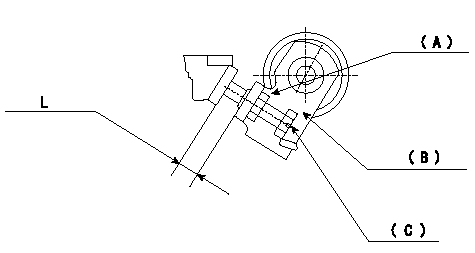
Starting injection quantity adjustment
Adjust adjusting bolt so that the starting injection quantity is within the standard.
Fix using nut.
(A): Lock nut.
(B): Stopping lever
(C): Adjustment bolt
----------
----------
L=5.9~8.2mm
----------
----------
L=5.9~8.2mm
0000001901 W-CSD ADJUSTMENT
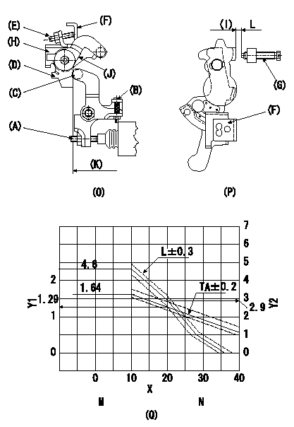
Adjustment of the W-CSD
1. Timer advance adjustment (refer to Fig 1 [O], 3 [Q]).
(1)Determine the timer advance angle from the graph in Fig. 3 (Q).
(2)(1) Adjust with the screw (A) so that the timer advance angle determined in the item (1) is obtained.
2. Setting the intermediate lever position (refer to fig 1 and fig 2)
(1)Insert a block gauge L1 between the idling set screw (G) and the control lever (F).
(2)Align the intermediate lever (D) with the aligning line (J) and position it perpendicularly.
3. W-CSD lever adjustment [refer to fig 1 (O) and fig 2 (P)]
(1)After completing (2) above, remove the block gauge L2.
(2)Insert a block gauge (I) L3 determined from the graph (L-theta) in figure 3 (Q) between the idling set screw (G) and the control lever (F).
(3)Fix screw (B) so that the W-CSD lever (C)'s roller contacts the intermediate lever (D). Fix using the nut.
Note:
The temperature of the wax at adjustment must not exceed a.
X:Temperature theta (deg C)
Y1:Timer stroke TA (mm)
Y2:Control lever L dimension (mm; control lever position)
K:Vertical position
M:TA-theta line
10 <= theta (deg C) <= 20: TA = -0.0355 theta + 1.995
20 <= theta (deg C) <= 60: TA = -0.03515 theta + 1.988
N:L-theta graph
theta (deg C) <= 10: L = 4.6
10 <= theta (deg C) <= 20: L = -0.17 theta + 6.3
20 <= theta (deg C) <= 28.5: L = -0.235 theta + 7.6
28.5 <= theta (deg C) <= 36: L = -0.12theta + 4.32
----------
L1=L=2.9+-0.05mm L2=2.9mm L3=L+-0.05mm a=30degC
----------
----------
L1=L=2.9+-0.05mm L2=2.9mm L3=L+-0.05mm a=30degC
----------
Information:
Illustration 74 g02026337 Appendix D
Cleaned Filter Specification
Note: Scope: The following steps determine a properly cleaned Caterpillar filter.Note: This specification applies to filters that were cleaned of ash only. This specification is only valid subsequent to the "Recommended Cleaning Procedure". This specification should not be used to determine if soot filled filters are properly cleaned. All filters must be baked appropriately using the "Recommended Cleaning Procedure" prior to application of this specification.HEALTH AND SAFETY
Wear goggles, gloves, protective clothing, and a National Institute for Occupational Safety and Health (NIOSH) approved P95 or N95 half-face respirator when handling a used Diesel Particulate Filter or Catalytic Converter Muffler. Failure to do so could result in personal injury.
Adhere to all local Health and Safety rules and regulations. Use all the personal protective equipment listed below:
Respirator
Safety shoes
Safety glasses
Latex gloves
Lab coatRESOURCESNecessary equipment:
38 cm (15 inch) long by 0.9 mm (0.04 inch) thick stainless steel probe for "200 cpsi" (Cells/Square inch) filters
Tape measureMETHODEvaluation of a cleaned filter:Note: A filter MUST meet all criteria in this section below to be considered clean.
Inspect both inlet and outlet surfaces for oil/fuel contamination, gouges and/or cracks. No cracks may be visible. Gouges may not be exceed 4.0 mm (0.15 inch) deep.
There must be no filter movement within the filters banding. This movement is defined as the substrate moving past the bent-over flange. The filter must be even or below the bent-over flange.
There must not be any signs of the steel fiber ring coming loose or any mat material (cottony gauze) slipping past the filter. See Illustration 75 below.
The flanges are not damaged beyond repair.
There are no dents deeper than 6.4 mm (0.25 inch) in the outer can of the filter and the outer can is not cracked, torn or otherwise breached.
No more than 20 cells are allowed to be damaged (showing soot) on the outlet face of the filter. Refer to Illustrations 76 and 77.
Inspect the ash depth in the cells using the "Check Cell Depth" instructions below.
Illustration 75 g02026392
Proper placement of the filter within the banding
(1) Outside Can
(2) Bent-over flange
(3) Steel fiber ring
(4) Mat material
(5) FilterNote: Filter must be below the bent over-flange (2).
Illustration 76 g02026398
Acceptable filter with less than 20 damaged cells
Illustration 77 g02026399
Unacceptable filter with too many damaged cells
Check Cell Depth
Check cell depth by dropping the stainless steel probe into a cell location noted by a dot in Illustration 78 below.
Lightly tap the probe with a finger until the probe does not travel into the cell any further. Mark the probe to record the depth.
Illustration 78 g02026405
Measure the distance from the tip of the probe which entered the cell to the mark made on the probe. This distance is the cell depth. Repeat this step 17 times per Illustration 78.
If the probe travels a minimum of 28.6 cm (11.25 inch) in all cells, the filter is considered clean.
If the probe encounters heavy resistance in