Information injection-pump assembly
ZEXEL
104748-1800
1047481800
ISUZU
8943235550
8943235550
Rating:
Cross reference number
ZEXEL
104748-1800
1047481800
ISUZU
8943235550
8943235550
Zexel num
Bosch num
Firm num
Name
Calibration Data:
Adjustment conditions
Test oil
1404 Test oil ISO4113orSAEJ967d
1404 Test oil ISO4113orSAEJ967d
Test oil temperature
degC
45
45
50
Nozzle
105000-2010
Bosch type code
NP-DN12SD12TT
Nozzle holder
105780-2080
Opening pressure
MPa
14.7
14.7
15.19
Opening pressure
kgf/cm2
150
150
155
Injection pipe
Inside diameter - outside diameter - length (mm) mm 2-6-840
Inside diameter - outside diameter - length (mm) mm 2-6-840
Transfer pump pressure
kPa
20
20
20
Transfer pump pressure
kgf/cm2
0.2
0.2
0.2
Direction of rotation (viewed from drive side)
Right R
Right R
Injection timing adjustment
Pump speed
r/min
800
800
800
Average injection quantity
mm3/st.
29
28.5
29.5
Difference in delivery
mm3/st.
2.5
Basic
*
Oil temperature
degC
50
48
52
Injection timing adjustment_02
Pump speed
r/min
500
500
500
Average injection quantity
mm3/st.
26.5
24.5
28.5
Oil temperature
degC
48
46
50
Injection timing adjustment_03
Pump speed
r/min
800
800
800
Average injection quantity
mm3/st.
29
28
30
Difference in delivery
mm3/st.
2.5
Basic
*
Oil temperature
degC
50
48
52
Injection quantity adjustment
Pump speed
r/min
900
900
900
Average injection quantity
mm3/st.
24
23
25
Difference in delivery
mm3/st.
6
Basic
*
Oil temperature
degC
50
48
52
Injection quantity adjustment_02
Pump speed
r/min
1100
1100
1100
Average injection quantity
mm3/st.
3
Oil temperature
degC
50
48
52
Injection quantity adjustment_03
Pump speed
r/min
900
900
900
Average injection quantity
mm3/st.
24
23
25
Difference in delivery
mm3/st.
6
Basic
*
Oil temperature
degC
50
48
52
Governor adjustment
Pump speed
r/min
375
375
375
Average injection quantity
mm3/st.
7.5
5.5
9.5
Difference in delivery
mm3/st.
2
Basic
*
Oil temperature
degC
48
46
50
Governor adjustment_02
Pump speed
r/min
375
375
375
Average injection quantity
mm3/st.
7.5
5.5
9.5
Difference in delivery
mm3/st.
2
Basic
*
Oil temperature
degC
48
46
50
Timer adjustment
Pump speed
r/min
100
100
100
Average injection quantity
mm3/st.
45
41.5
48.5
Basic
*
Oil temperature
degC
48
46
50
Remarks
Full
Full
Timer adjustment_02
Pump speed
r/min
100
100
100
Average injection quantity
mm3/st.
45
41.5
48.5
Oil temperature
degC
48
46
50
Speed control lever angle
Pump speed
r/min
375
375
375
Average injection quantity
mm3/st.
0
0
0
Oil temperature
degC
48
46
50
Remarks
Magnet OFF at idling position
Magnet OFF at idling position
0000000901
Pump speed
r/min
600
600
600
Overflow quantity
cm3/min
320
190
450
Oil temperature
degC
50
48
52
Stop lever angle
Pump speed
r/min
600
600
600
Pressure
kPa
294
274
314
Pressure
kgf/cm2
3
2.8
3.2
Basic
*
Oil temperature
degC
50
48
52
Stop lever angle_02
Pump speed
r/min
600
600
600
Pressure
kPa
294
265
323
Pressure
kgf/cm2
3
2.7
3.3
Basic
*
Oil temperature
degC
50
48
52
Stop lever angle_03
Pump speed
r/min
850
850
850
Pressure
kPa
353
314
392
Pressure
kgf/cm2
3.6
3.2
4
Oil temperature
degC
50
48
52
0000001101
Pump speed
r/min
1200
Timer stroke
mm
0
0
0
Basic
*
Oil temperature
degC
50
48
52
0000001201
Max. applied voltage
V
16
16
16
Test voltage
V
25
24
26
Timing setting
K dimension
mm
3.3
3.2
3.4
KF dimension
mm
5.8
5.7
5.9
MS dimension
mm
2.1
2
2.2
Control lever angle alpha
deg.
25
21
29
Control lever angle beta
deg.
22
17
27
Test data Ex:
0000001801 STARTING I/Q ADJUSTMENT
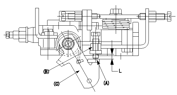
Starting injection quantity adjustment
Adjust the adjusting bolt A so that the starting injection quantity adjustment is within the standards. Fix using the nut B.
(C) Stop lever
L:Adjustment dimensions
----------
L=3.7~7.8mm
----------
L=3.7~7.8mm
----------
L=3.7~7.8mm
----------
L=3.7~7.8mm
Information:
Start By:a. remove cylinder head assemblyb. remove front housing groupc. remove flywheel housingd. remove crankshaft rear seal assemblye. remove piston and connecting rod assemblies 1. Remove bolts (1). Remove main bearing caps (2). Remove thrust bearings (3) from the center main. Main bearing caps are identified by numbers one through seven. Unmarked caps should be marked by stamping the appropriate number toward the right side on the bottom prior to the removal. 2. Install a suitable size bolt in each end of the crankshaft as shown. Fasten two lifting straps (4) to the bolts in the crankshaft and to a hoist as shown. Carefully, remove the crankshaft. The appropriate weight of the crankshaft is 129 kg (285 lb).3. Remove the upper portions of the main bearings. The following steps are for the installation of the crankshaft.
Be sure the main bearing tabs engage with the grooves in the block and cap.
4. Position the upper portion of the main bearings in the cylinder block. Lower the main bearing portion in caps (2). Be sure everything is clean and only the bearing face is lubricated with clean engine oil.5. Fasten a hoist to the crankshaft, and position it in the cylinder block. 6. Install thrust bearings (3).7. Install main bearing caps (2) with the part numbers toward the right hand side of the cylinder block. Take care to ensure the caps are numbered one through seven from the front of the engine. Put clean engine oil or molylube on the bolt threads and the washer face; then install bolts (1). Tighten the bolts on the side where the main bearing tabs are located to a torque of 95 5 N m (70 4 lb ft). Tighten the bolts on the opposite side to a torque of 95 5 N m (70 4 lb ft).8. Put a mark on each bolt head and the bearing caps. Turn the bolts that are opposite the main bearing tabs an additional 90° 5° turn. Then turn the bolts on the side where the main bearing tabs are located an additional 90° 5° turn.
Typical Example9. Use tooling (A) to measure crankshaft end play. The crankshaft end play must be 0.10 to 0.50 mm (.004 to .020 in).End By:a. install piston and connecting rod assembliesb. install crankshaft rear seal assemblyc. install flywheel housingd. install front housing groupe. install cylinder head assembly