Information injection-pump assembly
ZEXEL
104748-1720
1047481720

Rating:
Cross reference number
ZEXEL
104748-1720
1047481720
Zexel num
Bosch num
Firm num
Name
Calibration Data:
Adjustment conditions
Test oil
1404 Test oil ISO4113orSAEJ967d
1404 Test oil ISO4113orSAEJ967d
Test oil temperature
degC
45
45
50
Nozzle
105000-2010
Bosch type code
NP-DN12SD12TT
Nozzle holder
105780-2080
Opening pressure
MPa
14.7
14.7
15.19
Opening pressure
kgf/cm2
150
150
155
Injection pipe
Inside diameter - outside diameter - length (mm) mm 2-6-840
Inside diameter - outside diameter - length (mm) mm 2-6-840
Transfer pump pressure
kPa
20
20
20
Transfer pump pressure
kgf/cm2
0.2
0.2
0.2
Direction of rotation (viewed from drive side)
Right R
Right R
Injection timing adjustment
Pump speed
r/min
1500
1500
1500
Average injection quantity
mm3/st.
31.4
30.9
31.9
Difference in delivery
mm3/st.
2.5
Basic
*
Injection timing adjustment_02
Pump speed
r/min
600
600
600
Average injection quantity
mm3/st.
29.9
27.9
31.9
Injection timing adjustment_03
Pump speed
r/min
1000
1000
1000
Average injection quantity
mm3/st.
30.4
28.4
32.4
Injection timing adjustment_04
Pump speed
r/min
1500
1500
1500
Average injection quantity
mm3/st.
31.4
30.4
32.4
Difference in delivery
mm3/st.
2.5
Basic
*
Injection timing adjustment_05
Pump speed
r/min
2000
2000
2000
Average injection quantity
mm3/st.
30.1
28.1
32.1
Injection timing adjustment_06
Pump speed
r/min
2400
2400
2400
Average injection quantity
mm3/st.
28.4
26.4
30.4
Injection timing adjustment_07
Pump speed
r/min
2600
2600
2600
Average injection quantity
mm3/st.
27.6
25.5
29.7
Difference in delivery
mm3/st.
3.5
Injection quantity adjustment
Pump speed
r/min
2850
2850
2850
Average injection quantity
mm3/st.
15.9
12.9
18.9
Difference in delivery
mm3/st.
3.5
Basic
*
Injection quantity adjustment_02
Pump speed
r/min
2700
2700
2700
Average injection quantity
mm3/st.
26.8
23.3
30.3
Injection quantity adjustment_03
Pump speed
r/min
2850
2850
2850
Average injection quantity
mm3/st.
15.9
12.4
19.4
Difference in delivery
mm3/st.
3.5
Basic
*
Injection quantity adjustment_04
Pump speed
r/min
2975
2975
2975
Average injection quantity
mm3/st.
6
Governor adjustment
Pump speed
r/min
400
400
400
Average injection quantity
mm3/st.
9.6
7.6
11.6
Difference in delivery
mm3/st.
2
Basic
*
Governor adjustment_02
Pump speed
r/min
400
400
400
Average injection quantity
mm3/st.
9.6
7.6
11.6
Difference in delivery
mm3/st.
2
Governor adjustment_03
Pump speed
r/min
500
500
500
Average injection quantity
mm3/st.
5
Timer adjustment
Pump speed
r/min
100
100
100
Average injection quantity
mm3/st.
45
45
65
Basic
*
Remarks
Full
Full
Speed control lever angle
Pump speed
r/min
400
400
400
Average injection quantity
mm3/st.
0
0
0
Remarks
Magnet OFF at idling position
Magnet OFF at idling position
0000000901
Pump speed
r/min
1250
1250
1250
Overflow quantity
cm3/min
570
440
700
Stop lever angle
Pump speed
r/min
1250
1250
1250
Pressure
kPa
362.5
343
382
Pressure
kgf/cm2
3.7
3.5
3.9
Basic
*
Stop lever angle_02
Pump speed
r/min
500
500
500
Pressure
kPa
186
157
215
Pressure
kgf/cm2
1.9
1.6
2.2
Stop lever angle_03
Pump speed
r/min
1250
1250
1250
Pressure
kPa
363
334
392
Pressure
kgf/cm2
3.7
3.4
4
Basic
*
Stop lever angle_04
Pump speed
r/min
1500
1500
1500
Pressure
kPa
412
383
441
Pressure
kgf/cm2
4.2
3.9
4.5
Stop lever angle_05
Pump speed
r/min
2000
2000
2000
Pressure
kPa
539
510
568
Pressure
kgf/cm2
5.5
5.2
5.8
Stop lever angle_06
Pump speed
r/min
2300
2300
2300
Pressure
kPa
618
589
647
Pressure
kgf/cm2
6.3
6
6.6
0000001101
Pump speed
r/min
1250
1250
1250
Timer stroke
mm
2.9
2.7
3.1
Basic
*
_02
Pump speed
r/min
620
620
620
Timer stroke
mm
0.5
0.1
1.1
_03
Pump speed
r/min
1250
1250
1250
Timer stroke
mm
2.9
2.6
3.2
Basic
*
_04
Pump speed
r/min
1500
1500
1500
Timer stroke
mm
4.2
3.7
4.7
_05
Pump speed
r/min
2000
2000
2000
Timer stroke
mm
6.1
5.5
6.7
_06
Pump speed
r/min
2300
2300
2300
Timer stroke
mm
7.4
7
7.8
0000001201
Max. applied voltage
V
8
8
8
Test voltage
V
13
12
14
0000001401
Pump speed
r/min
1250
1250
1250
Average injection quantity
mm3/st.
18
17.5
18.5
Timer stroke variation dT
mm
0.8
0.6
1
Basic
*
_02
Pump speed
r/min
1250
1250
1250
Average injection quantity
mm3/st.
18
17
19
Timer stroke variation dT
mm
0.8
0.5
1.1
Basic
*
_03
Pump speed
r/min
1250
1250
1250
Average injection quantity
mm3/st.
7
5.5
8.5
Timer stroke variation dT
mm
2.2
1.7
2.7
Timing setting
K dimension
mm
3.3
3.2
3.4
KF dimension
mm
5.8
5.7
5.9
MS dimension
mm
1.4
1.3
1.5
Control lever angle alpha
deg.
20
16
24
Control lever angle beta
deg.
45
40
50
Test data Ex:
0000001801 W-CSD ADJUSTMENT
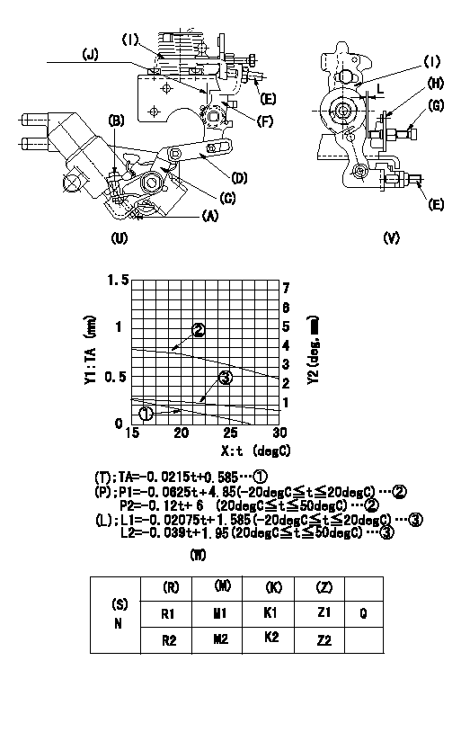
Adjustment of the W-CSD
1. Adjustment of the timer stroke
Adjust using screw (A) so that the timer stroke is the value determined using the graph (W) and the formula. [(U), (W)]
2. Adjustment of the position of the intermediate lever.
Insert a shim L1 between the control lever (I) and the idle set screw (G).
Align the intermediate lever (F) with the aligning line (J) and fix intermediate lever's adjusting screw (E) so that it contacts the control lever. [(U), (V)]
3. Adjustment of the FICD
Insert a shim between the control lever (I) and the idle set screw (G). Then, fix the CSD lever (C) in the position where it operates the intermediate lever (F) via the rod (D) using the adjusting screw (B). [(U), (V), (W)]
(J) Aligning mark
(T) Timer stroke (mm)
(P) Lever position (deg)
(L) Lever position (mm). Shows gap between control lever and idle set screw
X:Temperature t (deg C)
Y1:Timer stroke TA (mm)
Y2:Control lever position (deg, mm)
(R) Cooling water temperature (deg C)
(S) Cooling water temperature: increase direction
N:Pump speed
(M) Timer piston stroke (mm)
(K) Lever angle (deg)
(Z) Lever position (mm)
----------
L1=1.2+-0.05mm L=L1+-0.05mm
----------
L1=1.2+-0.05mm N=500r/min R1=20deg R2=-20deg M1=0.16+-0.2mm M2=1.0+-0.4mm K1=3.6+-1deg K2=6.1+-3deg Z1=1.2+-0.3mm Z2=2+-1mm
----------
L1=1.2+-0.05mm L=L1+-0.05mm
----------
L1=1.2+-0.05mm N=500r/min R1=20deg R2=-20deg M1=0.16+-0.2mm M2=1.0+-0.4mm K1=3.6+-1deg K2=6.1+-3deg Z1=1.2+-0.3mm Z2=2+-1mm
Information:
6V7070 Heavy-Duty Digital MultimeterThe 6V7070 Heavy-Duty Digital Multimeter is a completely portable, hand held instrument with a digital display. This multimeter is built with extra protection against damage in field applications, and is equipped with seven functions and 29 ranges. The 6V7070 Multimeter has an instant ohms indicator that permits continuity checking for fast circuit inspection. It also can be used for troubleshooting small value capacitors.The 6V7800 Regular-Duty Digital Multimeter (a low cost option to the Heavy-Duty Multimeter) is also available; however, the 6V7800 Multimeter does not have the 10A range or the instant ohms feature of the 6V7070 Multimeter. Make reference to Special Instruction, Form No. SEHS7734 for complete information for use of the 6V7070 and 6V7800 Multimeters.Battery
Never disconnect any charging unit circuit or battery circuit cable from the battery when the charging unit is operated. A spark can cause an explosion from the flammable vapor mixture of hydrogen and oxygen that is released from the electrolyte through the battery outlets. Injury to personnel can be the result.
The battery circuit is an electrical load on the charging unit. The load is variable because of the condition of the charge in the battery. Damage to the charging unit will result if the connections (either positive or negative) between the battery and charging unit are broken while the charging unit is in operation. This is because the battery load is lost and there is an increase in charging voltage. High voltage will damage, not only the charging unit, but also the regulator and other electrical components.Use the 4C4911 Battery Load Tester to load test a battery that does not hold a charge when in use. Refer to Operating Manual, Form No. SEHS9249 for more detailed instructions on use of the 4C4911 Battery Load Tester. See Special Instruction, Form No. SEHS7633, Battery Test Procedure, for the correct procedure and specifications to use when testing batteries.Charging System
The condition of charge in the battery at each regular inspection will show if the charging system operates correctly. An adjustment is necessary when the battery is constantly in a low condition of charge or a large amount of water is needed (more than one ounce of water per cell per week or per every 100 service hours).When it is possible, make a test of the charging unit and voltage regulator on the engine, and use wiring and components that are a permanent part of the system. Off-engine (bench) testing will give a test of the charging unit and voltage regulator operation. This testing will give an indication of needed repair. After repairs are made, again make a test to give proof that the units are repaired to their original condition of operation.To check for correct output of the alternator, see the Specifications module.For complete service information, refer to Service Manual Module, Form No. SENR3862. This module is part of REG00636 Service Manual.Before the start of on-engine testing, the charging system and battery must be checked as shown in the Steps that follow:1. Battery must