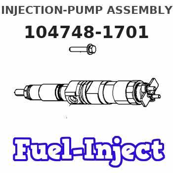
Information injection-pump assembly
ZEXEL
104748-1701
1047481701
ISUZU
8944405181
8944405181
Rating:
Cross reference number
ZEXEL
104748-1701
1047481701
ISUZU
8944405181
8944405181
Zexel num
Bosch num
Firm num
Name
Calibration Data:
Adjustment conditions
Test oil
1404 Test oil ISO4113orSAEJ967d
1404 Test oil ISO4113orSAEJ967d
Test oil temperature
degC
45
45
50
Nozzle
105000-2010
Bosch type code
NP-DN12SD12TT
Nozzle holder
105780-2080
Opening pressure
MPa
14.7
14.7
15.19
Opening pressure
kgf/cm2
150
150
155
Injection pipe
Inside diameter - outside diameter - length (mm) mm 2-6-840
Inside diameter - outside diameter - length (mm) mm 2-6-840
Transfer pump pressure
kPa
20
20
20
Transfer pump pressure
kgf/cm2
0.2
0.2
0.2
Direction of rotation (viewed from drive side)
Right R
Right R
Injection timing adjustment
Pump speed
r/min
1000
1000
1000
Average injection quantity
mm3/st.
23.4
22.9
23.9
Difference in delivery
mm3/st.
2
Basic
*
Injection timing adjustment_02
Pump speed
r/min
1400
1400
1400
Average injection quantity
mm3/st.
4.7
1.2
8.2
Injection timing adjustment_03
Pump speed
r/min
1300
1300
1300
Average injection quantity
mm3/st.
25.9
23.8
28
Injection timing adjustment_04
Pump speed
r/min
1000
1000
1000
Average injection quantity
mm3/st.
23.4
22.4
24.4
Injection timing adjustment_05
Pump speed
r/min
600
600
600
Average injection quantity
mm3/st.
22.3
20.3
24.3
Injection quantity adjustment
Pump speed
r/min
1400
1400
1400
Average injection quantity
mm3/st.
4.7
1.7
7.7
Difference in delivery
mm3/st.
2
Basic
*
Injection quantity adjustment_02
Pump speed
r/min
1450
1450
1450
Average injection quantity
mm3/st.
0
0
0
Governor adjustment
Pump speed
r/min
375
375
375
Average injection quantity
mm3/st.
5.3
3.3
7.3
Difference in delivery
mm3/st.
2
Basic
*
Governor adjustment_02
Pump speed
r/min
375
375
375
Average injection quantity
mm3/st.
5.3
3.3
7.3
Governor adjustment_03
Pump speed
r/min
425
425
425
Average injection quantity
mm3/st.
2
Timer adjustment
Pump speed
r/min
100
100
100
Average injection quantity
mm3/st.
50
45
55
Basic
*
Remarks
Refer to additional devices.
Refer to additional devices.
Speed control lever angle
Pump speed
r/min
375
375
375
Average injection quantity
mm3/st.
0
0
0
Remarks
Magnet OFF
Magnet OFF
0000000901
Pump speed
r/min
1000
1000
1000
Overflow quantity
cm3/min
361
230
492
Stop lever angle
Pump speed
r/min
1000
1000
1000
Pressure
kPa
392.5
373
412
Pressure
kgf/cm2
4
3.8
4.2
Basic
*
Stop lever angle_02
Pump speed
r/min
600
600
600
Pressure
kPa
284.5
255
314
Pressure
kgf/cm2
2.9
2.6
3.2
Stop lever angle_03
Pump speed
r/min
1000
1000
1000
Pressure
kPa
392.5
373
412
Pressure
kgf/cm2
4
3.8
4.2
Stop lever angle_04
Pump speed
r/min
1300
1300
1300
Pressure
kPa
470.5
441
500
Pressure
kgf/cm2
4.8
4.5
5.1
0000001101
Pump speed
r/min
1000
1000
1000
Timer stroke
mm
1.1
0.9
1.3
Basic
*
_02
Pump speed
r/min
850
750
950
Timer stroke
mm
0.5
0.5
0.5
_03
Pump speed
r/min
1000
1000
1000
Timer stroke
mm
1.1
0.8
1.4
_04
Pump speed
r/min
1300
1300
1300
Timer stroke
mm
2.4
1.9
2.9
_05
Pump speed
r/min
1500
1500
1500
Timer stroke
mm
3.3
2.9
3.7
0000001201
Max. applied voltage
V
8
8
8
Test voltage
V
13
12
14
Timing setting
K dimension
mm
3.3
3.2
3.4
KF dimension
mm
5.8
5.7
5.9
MS dimension
mm
2.5
2.4
2.6
Control lever angle alpha
deg.
25
21
29
Control lever angle beta
deg.
49
44
54
Information:
Marks For Tightening Connecting Rod Bolts-7E5996 Connecting Rod Assembly(1) Bore in connecting rod for piston pin bearing ... 55.436 0.013 mm (2.1825 .0005 in) The connecting rod must be heated for installation of piston pin bearing. Do not use a torch.(2) Distance rod may be heated to 175 to 260°C (347 to 500°F) to install the piston pin bearing ... 85.0 mm (3.35 in)(3) Bore in bearing for piston pin (new) ... 50.830 0.008 mm (2.0012 .0003 in) Diameter of piston pin (new) ... 50.795 0.005 mm (1.9998 .0002 in)Thoroughly lubricate piston pin with clean engine oil prior to inserting into piston group and rod assembly.Maximum permissible clearance between bearing and piston pin (worn) ... 0.25 mm (.010 in)(4) Bearing joint must be assembled at either location on centerline through the connecting rod bore ... 5°Make reference to Special Instruction, Form No. SMHS7295 for use of pin bearing removal and installation tools and procedures.(5) Distance between center of bearings ... 261.62 0.05 mm (10.300 .002 in)(6) Bore in connecting rod for bearing with nuts tightened to specifications (8) ... 96.200 0.013 mm (3.7874 .0005 in)(7) Location for etching cylinder number on connecting rod and cap. Rods and caps are to be marked with numbers 1 through 6 on the same side of the rod as the bearing tab slots.(8) Tighten connecting rod bolts as follows: a. Before installing bolts, lubricate bolt threads and seating faces of the caps with 2P2506 Thread Lubricant.b. Tighten each bolt to ... 90 8 N m (66 6 lb ft)c. Put an alignment mark on each cap and bolt.d. Tighten each bolt an additional ... 90 5° (1/4 turn)(9) Bore in bearing for crankshaft rod journal ... 90.112 0.028 mm (3.5477 .0011 in) Clearance between bearing and crankshaft (new) ... 0.062 to 0.160 mm (.0024 to .0063 in)Maximum permissible clearance between bearing and crankshaft (worn) ... 0.20 mm (.008 in) Bearings are available in 0.63 mm (.025 in) and 1.27 mm (.050 in) smaller than original size.