Information injection-pump assembly
ZEXEL
104748-0460
1047480460

Rating:
Cross reference number
ZEXEL
104748-0460
1047480460
Zexel num
Bosch num
Firm num
Name
104748-0460
INJECTION-PUMP ASSEMBLY
Calibration Data:
Adjustment conditions
Test oil
1404 Test oil ISO4113orSAEJ967d
1404 Test oil ISO4113orSAEJ967d
Test oil temperature
degC
45
45
50
Nozzle
105780-0060
Bosch type code
NP-DN0SD1510
Nozzle holder
105780-2150
Opening pressure
MPa
13
13
13.3
Opening pressure
kgf/cm2
133
133
136
Injection pipe
157805-5370
Injection pipe
Inside diameter - outside diameter - length (mm) mm 2-6-450
Inside diameter - outside diameter - length (mm) mm 2-6-450
Joint assembly
157641-4720
Tube assembly
157641-4020
Transfer pump pressure
kPa
20
20
20
Transfer pump pressure
kgf/cm2
0.2
0.2
0.2
Direction of rotation (viewed from drive side)
Right R
Right R
Injection timing adjustment
Pump speed
r/min
1500
1500
1500
Average injection quantity
mm3/st.
32.8
32.3
33.3
Difference in delivery
mm3/st.
2.5
Basic
*
Injection timing adjustment_02
Pump speed
r/min
2400
2400
2400
Average injection quantity
mm3/st.
14.7
12.2
17.2
Injection timing adjustment_03
Pump speed
r/min
2125
2125
2125
Average injection quantity
mm3/st.
33.2
30.1
36.3
Injection timing adjustment_04
Pump speed
r/min
1500
1500
1500
Average injection quantity
mm3/st.
32.8
31.8
33.8
Injection timing adjustment_05
Pump speed
r/min
500
500
500
Average injection quantity
mm3/st.
31.2
28.2
34.2
Injection quantity adjustment
Pump speed
r/min
2400
2400
2400
Average injection quantity
mm3/st.
14.7
12.7
16.7
Difference in delivery
mm3/st.
4
Basic
*
Injection quantity adjustment_02
Pump speed
r/min
2550
2550
2550
Average injection quantity
mm3/st.
7
Governor adjustment
Pump speed
r/min
350
350
350
Average injection quantity
mm3/st.
14.8
13.8
15.8
Difference in delivery
mm3/st.
2
Basic
*
Governor adjustment_02
Pump speed
r/min
1000
1000
1000
Average injection quantity
mm3/st.
5.8
Governor adjustment_03
Pump speed
r/min
450
450
450
Average injection quantity
mm3/st.
7.8
Governor adjustment_04
Pump speed
r/min
350
350
350
Average injection quantity
mm3/st.
14.8
13.3
16.3
Timer adjustment
Pump speed
r/min
100
100
100
Average injection quantity
mm3/st.
46
46
Basic
*
Remarks
Full
Full
Speed control lever angle
Pump speed
r/min
350
350
350
Average injection quantity
mm3/st.
0
0
0
Remarks
Magnet OFF
Magnet OFF
0000000901
Pump speed
r/min
1250
1250
1250
Overflow quantity
cm3/min
429
300
558
Stop lever angle
Pump speed
r/min
1250
1250
1250
Pressure
kPa
510
481
539
Pressure
kgf/cm2
5.2
4.9
5.5
Basic
*
Stop lever angle_02
Pump speed
r/min
1250
1250
1250
Pressure
kPa
510
481
539
Pressure
kgf/cm2
5.2
4.9
5.5
Stop lever angle_03
Pump speed
r/min
1500
1500
1500
Pressure
kPa
579
550
608
Pressure
kgf/cm2
5.9
5.6
6.2
Stop lever angle_04
Pump speed
r/min
2125
2125
2125
Pressure
kPa
745
716
774
Pressure
kgf/cm2
7.6
7.3
7.9
0000001101
Pump speed
r/min
1250
1250
1250
Timer stroke
mm
3.5
3.3
3.7
Basic
*
_02
Pump speed
r/min
1250
1250
1250
Timer stroke
mm
3.5
3.2
3.8
_03
Pump speed
r/min
1500
1500
1500
Timer stroke
mm
4.7
4.1
5.3
_04
Pump speed
r/min
2125
2125
2125
Timer stroke
mm
7.6
6.8
8.4
_05
Pump speed
r/min
650
650
650
Timer stroke
mm
0.7
-0.1
1.5
_06
Pump speed
r/min
600
450
750
Timer stroke
mm
0.5
0.5
0.5
0000001201
Max. applied voltage
V
8
8
8
Test voltage
V
13
12
14
0000001401
Pump speed
r/min
1250
1250
1250
Average injection quantity
mm3/st.
25
24
26
Timer stroke variation dT
mm
0.8
0.6
1
Basic
*
_02
Pump speed
r/min
1250
1250
1250
Average injection quantity
mm3/st.
25
23.5
26.5
Timer stroke variation dT
mm
0.8
0.5
1.1
_03
Pump speed
r/min
1250
1250
1250
Average injection quantity
mm3/st.
19.2
17.7
20.7
Timer stroke variation dT
mm
2
2
2
Timing setting
K dimension
mm
3.3
3.2
3.4
KF dimension
mm
5.8
5.7
5.9
MS dimension
mm
1.5
1.4
1.6
Control lever angle alpha
deg.
30
26
34
Control lever angle beta
deg.
44
41
47
Test data Ex:
0000001801 IDLING SWITCH ADJUSTMENT
Idle switch confirmation
Confirm that the switch turns ON at the idle lever position.
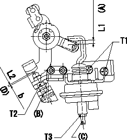
Adjustment of the V-FICD
1. V-FICD installation position adjustment
(1)Hold the control lever in the position a.
(2)Adjust the position of the bracket so that the clearance between the control lever's roller and the actuator's hook at initial installation is L1. Then, fix using the nut.
2. V-FICD stroke adjustment
(1)Move the actuator through its full stroke.
(2)Adjust the adjusting screw so that the control lever position is b (the distance between the control lever and the idle switch is L2), then fix using the nut.
(3)Confirm full stroke at P1 {P2}.
(A): (distance at installation)
(B): idle switch
(C): adjusting screw
(D) : (from idle)
----------
a=0deg b=2.5deg L1=3+-1mm L2=1.6+-1mm P1=-66.7kPa P2=-500mmHg
----------
b=2.5deg L1=3+-1mm L2=1.6+-1mm T1=6~9N-m(0.6~0.9kgf-m) T2=12~15N-m(1.2~1.5kgf-m) T3=1.2~1.5Nm(0.12~0.15kgf-m)
----------
a=0deg b=2.5deg L1=3+-1mm L2=1.6+-1mm P1=-66.7kPa P2=-500mmHg
----------
b=2.5deg L1=3+-1mm L2=1.6+-1mm T1=6~9N-m(0.6~0.9kgf-m) T2=12~15N-m(1.2~1.5kgf-m) T3=1.2~1.5Nm(0.12~0.15kgf-m)
0000001901 M-CSD ADJUSTMENT
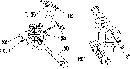
M-CSD adjustment
1. Fixing the M-CSD
(1)At roller holder advance angle a adjust the lever shaft ball pin so that it contacts the roller holder.
(2)At this time, adjust the position of the M-CSD lever (A) using adjusting screw (C) so that the clearance between the M-CSD lever (A) and the stopper (B) becomes L1. Then fix using nut (D).
2. M-FICD adjustment
(1)Move the CSD lever A through its full stroke (until the stopper B contacts the other face).
(2)Adjust screw E so that the control lever G's position is b (the gap between the control lever and the idling set screw is L2). Then fix using the nut F.
H:From idle
----------
L1=0.5+2mm L2=3+-1mm a=0deg b=4.5deg
----------
L1=0.5+2mm L2=3+-1mm b=4.5deg T=6~9N-m(0.6~0.9kgf-m)
----------
L1=0.5+2mm L2=3+-1mm a=0deg b=4.5deg
----------
L1=0.5+2mm L2=3+-1mm b=4.5deg T=6~9N-m(0.6~0.9kgf-m)
0000002001 POTENTIOMETER ADJUSTMENT
Confirm potentiometer output voltage
Control lever (1) Full position: V1 (Adjusting point)
(2)Idle position: V2 (checking point)
Applied voltage Vi
----------
V1=9.1+-0.03V V2=1.6+-0.7V Vi=10.00V
----------
----------
V1=9.1+-0.03V V2=1.6+-0.7V Vi=10.00V
----------
Information:
1. Remove fuel line (1) and (3) from the fuel transfer pump.2. Put caps in the fuel line openings to prevent fuel system contamination.3. Remove bolts (2), and remove fuel transfer pump (4). Check the condition of the O-ring seal on the fuel transfer pump. If necessary, make a replacement. The following steps are for installtion of the fuel transfer pump.4. Be sure the O-ring seal is in position on the fuel transfer pump. Put clean engine oil on the O-ring seal.5. Put fuel transfer pump (4) in position, and install the bolts that hold it in place.6. Remove the caps from the fuel line openings, and install fuel lines (1) and (3).Disassemble Fuel Transfer Pump
Start By:a. remove fuel transfer pump 1. Remove seal (1) from the fuel transfer pump.
Cover (2) is under spring tension. Remove the bolts that hold cover (2) slowly to prevent injury.
2. Remove bolts (3) and cover (2) from the housing. 3. Remove seals (4) and valve (5) from cover (2). 4. Remove spring (6) from the piston.
Mark the orientation of valve (8) as to its location in the housing.
5. Remove washer (7), valve (8) and the seal from the housing. 6. Remove piston (9) and sleeve (10) from the housing. 7. Remove seal (11) from sleeve (12). 8. Remove guide and tappet assembly (13) from the housing. 9. Remove seal (14) from guide (15).
If tappet (17) or the guide are damaged or worn, they must be replaced as a unit.
10. Remove ring (16) from tappet (17) and the tappet from guide (15). 11. Remove the bolts and cover (18) from the housing. 12. Remove seal (19) from cover (18). 13. Remove valve (20) from the housing if necessary.Assemble Fuel Transfer Pump
1. Install valve (20) in housing as shown. 2. Put clean fuel on seal (19), and install it on cover (18).3. Install cover (18) on the housing.
The tappet and guide must be serviced as a unit.
4. Install tappet (17) in guide (15). Install ring (16) on tappet (17) to hold the tappet in the guide. 5. Put clean fuel on seal (14), and install it on guide and tappet assembly (13).6. Install guide and tappet assembly (13) in the housing as shown. 7. Put clean fuel on seal (11), and install it on sleeve (12).8. Install sleeve (12) in the housing. 9. Install piston (9) in the housing. 10. Install seal, valve (8) and washer (7) in the housing as shown. Be sure valve (8) is the correct position in the housing. 11. Install spring (6) in the piston. 12. Install valve (5) in cover (2) as shown.13. Put clean fuel on seals (4), and put them in position on cover (2).14. Install cover (2) on the housing. 15. Put seal (1) in position on the fuel transfer pump.16. Install the fuel transfer pump on the fuel injection pump housing.End By:a. install fuel transfer pump
Have questions with 104748-0460?
Group cross 104748-0460 ZEXEL
104748-0460
INJECTION-PUMP ASSEMBLY