Information injection-pump assembly
ZEXEL
104748-0390
1047480390
MAZDA
RFD313800
rfd313800
Rating:
Cross reference number
ZEXEL
104748-0390
1047480390
MAZDA
RFD313800
rfd313800
Zexel num
Bosch num
Firm num
Name
Calibration Data:
Adjustment conditions
Test oil
1404 Test oil ISO4113orSAEJ967d
1404 Test oil ISO4113orSAEJ967d
Test oil temperature
degC
45
45
50
Nozzle
105000-2010
Bosch type code
NP-DN12SD12TT
Nozzle holder
105780-2080
Opening pressure
MPa
14.7
14.7
15.19
Opening pressure
kgf/cm2
150
150
155
Injection pipe
Inside diameter - outside diameter - length (mm) mm 2-6-840
Inside diameter - outside diameter - length (mm) mm 2-6-840
Transfer pump pressure
kPa
20
20
20
Transfer pump pressure
kgf/cm2
0.2
0.2
0.2
Direction of rotation (viewed from drive side)
Right R
Right R
Injection timing adjustment
Pump speed
r/min
1375
1375
1375
Average injection quantity
mm3/st.
35.9
35.4
36.4
Difference in delivery
mm3/st.
2.5
Basic
*
Injection timing adjustment_02
Pump speed
r/min
2600
2600
2600
Average injection quantity
mm3/st.
12.8
10.3
15.3
Injection timing adjustment_03
Pump speed
r/min
2325
2325
2325
Average injection quantity
mm3/st.
32.2
30.1
34.3
Injection timing adjustment_04
Pump speed
r/min
1375
1375
1375
Average injection quantity
mm3/st.
35.9
34.9
36.9
Injection timing adjustment_05
Pump speed
r/min
600
600
600
Average injection quantity
mm3/st.
31
29
33
Injection quantity adjustment
Pump speed
r/min
2600
2600
2600
Average injection quantity
mm3/st.
12.8
10.8
14.8
Difference in delivery
mm3/st.
4
Basic
*
Injection quantity adjustment_02
Pump speed
r/min
2700
2700
2700
Average injection quantity
mm3/st.
6
Governor adjustment
Pump speed
r/min
360
360
360
Average injection quantity
mm3/st.
10
9
11
Difference in delivery
mm3/st.
2
Basic
*
Governor adjustment_02
Pump speed
r/min
360
360
360
Average injection quantity
mm3/st.
10
9
11
Governor adjustment_03
Pump speed
r/min
450
450
450
Average injection quantity
mm3/st.
4
Timer adjustment
Pump speed
r/min
100
100
100
Average injection quantity
mm3/st.
42
42
Basic
*
Speed control lever angle
Pump speed
r/min
360
360
360
Average injection quantity
mm3/st.
0
0
0
Remarks
Magnet OFF
Magnet OFF
0000000901
Pump speed
r/min
1375
1375
1375
Overflow quantity
cm3/min
411
282
540
Stop lever angle
Pump speed
r/min
1375
1375
1375
Pressure
kPa
460.5
431
490
Pressure
kgf/cm2
4.7
4.4
5
Basic
*
Stop lever angle_02
Pump speed
r/min
1375
1375
1375
Pressure
kPa
460.5
431
490
Pressure
kgf/cm2
4.7
4.4
5
Stop lever angle_03
Pump speed
r/min
1800
1800
1800
Pressure
kPa
578.5
549
608
Pressure
kgf/cm2
5.9
5.6
6.2
Stop lever angle_04
Pump speed
r/min
2325
2325
2325
Pressure
kPa
706
677
735
Pressure
kgf/cm2
7.2
6.9
7.5
0000001101
Pump speed
r/min
1375
1375
1375
Timer stroke
mm
4.2
4
4.4
Basic
*
_02
Pump speed
r/min
1375
1375
1375
Timer stroke
mm
4.2
3.9
4.5
_03
Pump speed
r/min
1800
1800
1800
Timer stroke
mm
6.7
6.1
7.3
_04
Pump speed
r/min
2325
2325
2325
Timer stroke
mm
7.8
7.4
8.2
0000001201
Max. applied voltage
V
8
8
8
Test voltage
V
13
12
14
0000001401
Pump speed
r/min
1375
1375
1375
Average injection quantity
mm3/st.
28
27
29
Timer stroke variation dT
mm
3.6
3.4
3.8
Basic
*
_02
Pump speed
r/min
1375
1375
1375
Average injection quantity
mm3/st.
28
26.5
29.5
Timer stroke variation dT
mm
3.6
3.3
3.9
_03
Pump speed
r/min
1375
1375
1375
Average injection quantity
mm3/st.
16
14.5
17.5
Timer stroke variation dT
mm
2.4
1.8
3
Timing setting
K dimension
mm
3.3
3.2
3.4
KF dimension
mm
5.8
5.7
5.9
MS dimension
mm
1.5
1.4
1.6
Control lever angle alpha
deg.
25
21
29
Control lever angle beta
deg.
45
40
50
Test data Ex:
0000001801 SIDE LINK LEVER ADJUSTMENT
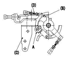
Side link lever adjustment
1. Adjusting the side link lever
(1)Hold the control lever in the position a.
(2)Adjust the length of the rod D so that a pin L1 can pass between the side link B and the actuator bracket C at A, then fix.
Wire length confirmation
Accelerator wire
(1)Idle position: L2
(2)Idle~full: L3
----------
a=0deg L1=Dia.5.8-0.2mm L2=161+-3mm L3=34.0+-4mm
----------
----------
a=0deg L1=Dia.5.8-0.2mm L2=161+-3mm L3=34.0+-4mm
----------
0000001901 W-CSD ADJUSTMENT
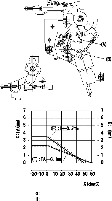
Adjustment of the W-CSD
1. Adjustment of the advance angle of the timer
Adjust using screw A so that timer lift is the value determined from the graph.
2. Adjust dimension L.
Adjust using the turnbuckle B so that L is the value determined from the graph.
C = timer lift
D = control lever dimension I
(E) = control lever gap
(F) = timer stroke
X = temperature t
----------
----------
G=(F):TA(mm)=-0.04t+2.4(t>=0degC) H=(E):l(mm)=-0.072t3.6(t>=0degC)
----------
----------
G=(F):TA(mm)=-0.04t+2.4(t>=0degC) H=(E):l(mm)=-0.072t3.6(t>=0degC)
0000002001 DASHPOT ADJUSTMENT
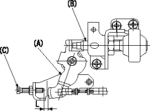
Adjustment of the dash pot
Adjust the position of the dashpot (B) so that the end of the dashpot contacts the control lever (A) when the control lever is a from the idle position [the clearance between the idle screw (C) and the control lever is L]. Then, fix the nut.
D = nut
----------
L=7.2+-1mm a=10.5deg
----------
SW=SW22 L=7.2+-1mm
----------
L=7.2+-1mm a=10.5deg
----------
SW=SW22 L=7.2+-1mm
Information:
Start By:a. remove timing gear coverb. remove flywheel housingc. remove pistons and connecting rod assembliesd. remove crankshaft rear seal and wear sleevee. remove crankshaft front seal and wear sleeve Check the bearing caps for a number as to their location. If a number can be seen, put a number on the left side of the cylinder block and bearing cap. 1. Remove bolts (1) that hold main bearing caps (2) to the block, and remove main bearing caps (2). 2. Install one of the bolts from the front pulley in each end of the crankshaft.3. Fasten a hoist to the crankshaft (3), and remove crankshaft (3) from the block. The weight is 159 kg (350 lb.). If new main bearings are not to be installed, keep old bearings with identification as to their location in cylinder block. 4. Use tooling (A) to remove the crankshaft gear.5. Use tooling (B) if necessary to remove the dowel and the pin.Install Crankshaft
If the crankshaft journals and bores for the block and rods were measured at disassembly and found to be within specifications, no further checks are necessary. However, if the serviceman still wants to measure the bearing clearances, Plastigage is recommended. Lead wire, shim stock or use of a dial bore gauge can damage the bearing surface.
The servicemen must be very careful to use Plastigage, tool (B) correctly. The following points must be remembered:...Make sure that the backs of the bearings and the bores are clean and dry....Make sure that the bearing locking tabs are properly seated in their slots....The crankshaft must be free of oil where the Plastigage touches it....If the main bearing clearances are checked with the engine upright or on its side, the crankshaft must be supported. Use a jack under an adjacent crankshaft counterweight and hold the crankshaft against the crown of the bearing. If the crankshaft is not supported, the weight of the crankshaft will cause incorrect readings....Put a piece of Plastigage on the crown of the bearing half that is in the cap. Do not allow the Plastigage to extend over the edge of the bearing....Install the bearing cap using the correct torque-turn specifications. Do not use an impact wrench. Be careful not to dislodge the bearing when the cap is installed....Do not turn the crankshaft with the Plastigage installed....Carefully remove the cap but do not remove the Plastigage. Measure the width of the Plastigage while it is in the bearing cap or on the crankshaft journal. Do this by using the correct scale on the package. Record the measurements....Remove the Plastigage before reinstalling the cap.When using Plastigage, the readings can sometimes be unclear. For example, all parts of the Plastigage are not the same width. Measure the major widths to make sure that they are within the specification range. Also, experience has shown that when checking clearances tighter than 0.10 mm (.004") the readings may be low by 0.013 to 0.025 mm (.0005 to .0010"). Out-of-round journals can give faulty readings. Also, journal taper