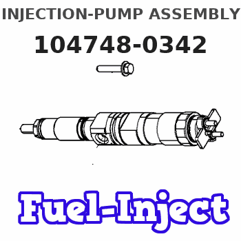
Information injection-pump assembly
ZEXEL
104748-0342
1047480342
Rating:
Cross reference number
ZEXEL
104748-0342
1047480342
Zexel num
Bosch num
Firm num
Name
Calibration Data:
Adjustment conditions
Test oil
1404 Test oil ISO4113orSAEJ967d
1404 Test oil ISO4113orSAEJ967d
Test oil temperature
degC
45
45
50
Nozzle
105000-2010
Bosch type code
NP-DN12SD12TT
Nozzle holder
105780-2080
Opening pressure
MPa
14.7
14.7
15.19
Opening pressure
kgf/cm2
150
150
155
Injection pipe
Inside diameter - outside diameter - length (mm) mm 2-6-840
Inside diameter - outside diameter - length (mm) mm 2-6-840
Transfer pump pressure
kPa
20
20
20
Transfer pump pressure
kgf/cm2
0.2
0.2
0.2
Direction of rotation (viewed from drive side)
Right R
Right R
Injection timing adjustment
Pump speed
r/min
1375
1375
1375
Average injection quantity
mm3/st.
35.7
35.2
36.2
Difference in delivery
mm3/st.
2.5
Basic
*
Oil temperature
degC
50
48
52
Injection timing adjustment_02
Pump speed
r/min
1375
1365
1385
Average injection quantity
mm3/st.
35.7
34.7
36.7
Difference in delivery
mm3/st.
3
Oil temperature
degC
50
48
52
Injection timing adjustment_03
Pump speed
r/min
2325
2315
2335
Average injection quantity
mm3/st.
32
30.4
33.6
Oil temperature
degC
52
50
54
Injection quantity adjustment
Pump speed
r/min
2600
2600
2600
Average injection quantity
mm3/st.
12.7
10.7
14.7
Difference in delivery
mm3/st.
4
Basic
*
Oil temperature
degC
55
52
58
Injection quantity adjustment_02
Pump speed
r/min
2700
2700
2700
Average injection quantity
mm3/st.
6
Oil temperature
degC
55
52
58
Injection quantity adjustment_03
Pump speed
r/min
2600
2590
2610
Average injection quantity
mm3/st.
12.7
10.7
14.7
Oil temperature
degC
55
52
58
Governor adjustment
Pump speed
r/min
360
360
360
Average injection quantity
mm3/st.
10
9
11
Difference in delivery
mm3/st.
2
Basic
*
Oil temperature
degC
48
46
50
Governor adjustment_02
Pump speed
r/min
360
350
370
Average injection quantity
mm3/st.
10
9
11
Difference in delivery
mm3/st.
2.5
Oil temperature
degC
48
46
50
Timer adjustment
Pump speed
r/min
100
100
100
Average injection quantity
mm3/st.
42
42
Basic
*
Oil temperature
degC
48
46
50
Speed control lever angle
Pump speed
r/min
360
360
360
Average injection quantity
mm3/st.
0
0
0
Oil temperature
degC
48
46
50
Remarks
Magnet OFF at idling position
Magnet OFF at idling position
0000000901
Pump speed
r/min
1375
1375
1375
Overflow quantity
cm3/min
410
280
540
Oil temperature
degC
50
48
52
Stop lever angle
Pump speed
r/min
1375
1375
1375
Pressure
kPa
461
432
490
Pressure
kgf/cm2
4.7
4.4
5
Basic
*
Oil temperature
degC
50
48
52
Stop lever angle_02
Pump speed
r/min
1375
1365
1385
Pressure
kPa
460.5
431
490
Pressure
kgf/cm2
4.7
4.4
5
Oil temperature
degC
50
48
52
Stop lever angle_03
Pump speed
r/min
1800
1790
1810
Pressure
kPa
578.5
549
608
Pressure
kgf/cm2
5.9
5.6
6.2
Oil temperature
degC
50
48
52
0000001101
Pump speed
r/min
1375
1375
1375
Timer stroke
mm
4.2
4
4.4
Basic
*
Oil temperature
degC
50
48
52
_02
Pump speed
r/min
1375
1365
1385
Timer stroke
mm
4.2
4
4.4
Oil temperature
degC
50
48
52
_03
Pump speed
r/min
1800
1790
1810
Timer stroke
mm
6.7
6.3
7.1
Oil temperature
degC
50
48
52
0000001201
Max. applied voltage
V
8
8
8
Test voltage
V
13
12
14
0000001401
Pump speed
r/min
1375
1375
1375
Average injection quantity
mm3/st.
28
27
29
Timer stroke TA
mm
3.6
3.4
3.8
Basic
*
Oil temperature
degC
50
48
52
_02
Pump speed
r/min
1375
1375
1375
Average injection quantity
mm3/st.
16
15
17
Timer stroke TA
mm
2.4
1.9
2.9
Basic
*
Oil temperature
degC
50
48
52
_03
Pump speed
r/min
1375
1365
1385
Average injection quantity
mm3/st.
28
26
30
Timer stroke TA
mm
3.6
3.4
3.8
Oil temperature
degC
50
48
52
Timing setting
K dimension
mm
3.3
3.2
3.4
KF dimension
mm
5.8
5.7
5.9
MS dimension
mm
1.5
1.4
1.6
Control lever angle alpha
deg.
25
21
29
Control lever angle beta
deg.
45
40
50
Test data Ex:
0000001801 SIDE LINK LEVER ADJUSTMENT
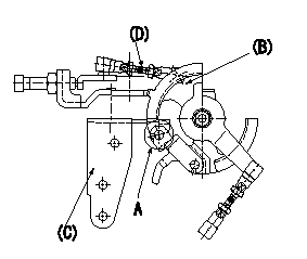
Side link lever adjustment
1. Hold the control lever at position a.
2. At A, adjust the length of rod (D) so that a pin L1 can pass through side link (B) and actuator bracket (C), and then fix.
----------
a=0deg L1=Dia.5.8-0.2mm
----------
----------
a=0deg L1=Dia.5.8-0.2mm
----------
0000001901 W-CSD ADJUSTMENT
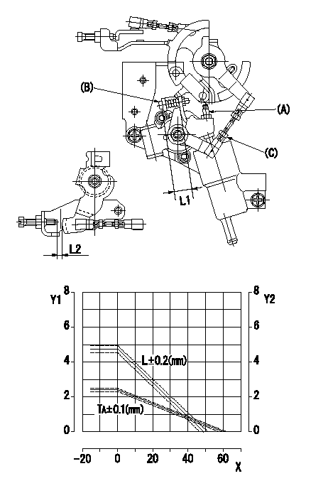
Adjustment of the W-CSD
1. Determine the timer advance.
2. Adjust using screw (A) so that the timer advance is as determined in (1).
3. Adjust using the screw (B) to obtain L1.
4. Adjust so that the control lever gap L2 is as determined from the graph.
TA = -0.04t + 2.4
L=-0.0965t+4.77
Y1 = timer stroke TA (mm)
Y2 = control lever gap L (mm)
X = temperature t (deg C)
----------
L1=12.3+-0.5mm
----------
L1=12.3+-0.5mm
----------
L1=12.3+-0.5mm
----------
L1=12.3+-0.5mm
0000002001 DASHPOT ADJUSTMENT
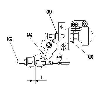
Adjustment of the dash pot
1. Move the control lever (A) a from idle (gap between idle screw (C) and control lever is L).
2. Adjust the position of the dashpot (B) so that the end of the dashpot contacts the control lever.
3. Fix (D) using the SW22 nut.
----------
a=13deg L=9+-1mm
----------
L=9+-1mm
----------
a=13deg L=9+-1mm
----------
L=9+-1mm
Information:
Make reference to Guideline For Reusable Parts; Pistons, Form No. SEBF8049; Cylinder Liners, Form No. SEBF8068; and Piston Pins And Retaining Rings, Form No. SEBF8051. For installation, number on tab groove side of connecting rod is to be positioned toward opposite side of engine from camshaft.Top And Intermediate Ring
The 8T3150 Keystone Piston Ring Groove Gauge is necessary for measuring ring groove in keystone style pistons. For correct use of the gauge group, see the instruction card that is with the gauge group.Install piston rings with "UP" side toward top of piston.(1) Top Ring has the mark "UP-1."(2) Intermediate ring has the mark "UP-2".Clearance between ends of piston ring when installed in a cylinder liner with a bore size of 137.16 mm (5.400 in)Top ring ... 0.724 0.191 mm (.0285 .0075 in)Intermediate ring ... 1.080 0.190 mm (.0425 .0075 in)Increase in clearance between ends of piston rings for each 0.03 mm (.001 in) increase in cylinder liner bore size ... 0.08 mm (.003 in)Oil Control Ring
(3) Install oil control ring with the gap in the spring 180° away from the gap in the ring. White portion of spring must be visible at the ring end gap.Width of groove in piston for piston ring (new) ... 3.210 0.010 mm (.1264 .0004 in)Thickness of piston ring (new) ... 3.137 0.013 mm (.1235 .0005 in)Clearance between groove and piston ring (new) ... 0.073 0.023 mm (.0029 .0009 in)Maximum permissible clearance (worn) ... 0.15 mm (.006 in)Clearance between ends of piston ring when installed in a cylinder liner with a bore size of 137.16 mm (5.400 in) ... 0.572 0.191 mm (.0225 .0075 in)Increase in clearance between ends of piston ring for each 0.03 mm (.001 in) increase in cylinder liner bore size ... 0.08 mm (.003 in)Piston Pin Bore
(4) Bore in piston for pin. 1991 Model with elliptical pin bore (310 - 425 hp) Vertical ... 50.814 0.004 mm (2.0005 .0001 in)Horizontal ... actual vertical diameter plus 0.032 to 0.048 mm (.0012 to .0019 in)Clearance between pin and bore in piston ... 0.010 to 0.028 mm (.0004 to .0011 in)Permissible clearance (worn) ... 0.05 mm (.002 in)Pin diameter ... 50.795 0.005 mm (1.9998 .0002 in) Low Crevice Volume and Gallery Pistons Bore in piston for pin ... 50.814 0.004 mm (2.0005 .0001 in)Clearance between pin and bore in piston ... 0.010 to 0.028 mm (.0004 to .0011 in)Permissible clearance (worn) ... 0.05 mm (.002 in)Pin diameter ... 50.795 0.005 mm (1.9998 .0002 in)All Other Pistons Bore in piston for pin ... 50.815 0.008 mm (2.0006 .0003 in)Clearance between pin and bore in piston ... 0.007 to 0.032 mm (.0003 to .0013 in)Permissible clearance (worn) ... 0.05 mm (.002 in)Pin diameter ... 50.795 0.005 mm (1.9998 .0002 in)