Information injection-pump assembly
BOSCH
9 460 610 230
9460610230
ZEXEL
104748-0242
1047480242
MAZDA
RF3913800B
rf3913800b

Rating:
Cross reference number
BOSCH
9 460 610 230
9460610230
ZEXEL
104748-0242
1047480242
MAZDA
RF3913800B
rf3913800b
Zexel num
Bosch num
Firm num
Name
Calibration Data:
Adjustment conditions
Test oil
1404 Test oil ISO4113orSAEJ967d
1404 Test oil ISO4113orSAEJ967d
Test oil temperature
degC
45
45
50
Nozzle
105000-2010
Bosch type code
NP-DN12SD12TT
Nozzle holder
105780-2080
Opening pressure
MPa
14.7
14.7
15.19
Opening pressure
kgf/cm2
150
150
155
Injection pipe
Inside diameter - outside diameter - length (mm) mm 2-6-840
Inside diameter - outside diameter - length (mm) mm 2-6-840
Transfer pump pressure
kPa
20
20
20
Transfer pump pressure
kgf/cm2
0.2
0.2
0.2
Direction of rotation (viewed from drive side)
Left L
Left L
Injection timing adjustment
Pump speed
r/min
1375
1375
1375
Average injection quantity
mm3/st.
35.9
35.4
36.4
Difference in delivery
mm3/st.
2.5
Basic
*
Injection timing adjustment_02
Pump speed
r/min
2600
2600
2600
Average injection quantity
mm3/st.
12.8
9.8
15.8
Injection timing adjustment_03
Pump speed
r/min
2325
2325
2325
Average injection quantity
mm3/st.
32.2
30.2
34.2
Injection timing adjustment_04
Pump speed
r/min
1375
1375
1375
Average injection quantity
mm3/st.
35.9
34.9
36.9
Injection timing adjustment_05
Pump speed
r/min
600
600
600
Average injection quantity
mm3/st.
31
29
33
Injection quantity adjustment
Pump speed
r/min
2600
2600
2600
Average injection quantity
mm3/st.
12.8
10.8
14.8
Basic
*
Injection quantity adjustment_02
Pump speed
r/min
2700
2700
2700
Average injection quantity
mm3/st.
6
Governor adjustment
Pump speed
r/min
410
410
410
Average injection quantity
mm3/st.
8
7
9
Difference in delivery
mm3/st.
2
Basic
*
Governor adjustment_02
Pump speed
r/min
410
410
410
Average injection quantity
mm3/st.
8
6
10
Timer adjustment
Pump speed
r/min
100
100
100
Average injection quantity
mm3/st.
42
42
Basic
*
Speed control lever angle
Pump speed
r/min
410
410
410
Average injection quantity
mm3/st.
0
0
0
Remarks
Magnet OFF
Magnet OFF
0000000901
Pump speed
r/min
1375
1375
1375
Overflow quantity
cm3/min
410
278
542
Stop lever angle
Pump speed
r/min
1375
1375
1375
Pressure
kPa
460.5
431
490
Pressure
kgf/cm2
4.7
4.4
5
Basic
*
Stop lever angle_02
Pump speed
r/min
600
600
600
Pressure
kPa
245.5
216
275
Pressure
kgf/cm2
2.5
2.2
2.8
Stop lever angle_03
Pump speed
r/min
1375
1375
1375
Pressure
kPa
460.5
431
490
Pressure
kgf/cm2
4.7
4.4
5
Stop lever angle_04
Pump speed
r/min
2325
2325
2325
Pressure
kPa
706
677
735
Pressure
kgf/cm2
7.2
6.9
7.5
0000001101
Pump speed
r/min
1375
1375
1375
Timer stroke
mm
4.2
4
4.4
Basic
*
_02
Pump speed
r/min
1375
1375
1375
Timer stroke
mm
4.2
3.9
4.5
_03
Pump speed
r/min
1800
1800
1800
Timer stroke
mm
6.7
6.1
7.3
_04
Pump speed
r/min
2325
2325
2325
Timer stroke
mm
7.8
7.2
8.4
0000001201
Max. applied voltage
V
8
8
8
Test voltage
V
13
12
14
0000001401
Pump speed
r/min
1375
1375
1375
Average injection quantity
mm3/st.
28.2
27.2
29.2
Timer stroke TA
mm
3.6
3.4
3.8
Basic
*
_02
Pump speed
r/min
1375
1375
1375
Average injection quantity
mm3/st.
28.2
26.7
29.7
Timer stroke TA
mm
3.6
3.3
3.9
_03
Pump speed
r/min
1375
1375
1375
Average injection quantity
mm3/st.
16.1
14.6
17.6
Timer stroke TA
mm
2.4
1.7
3.1
Timing setting
K dimension
mm
3.3
3.2
3.4
KF dimension
mm
5.8
5.7
5.9
MS dimension
mm
1.5
1.4
1.6
Control lever angle alpha
deg.
20
16
24
Control lever angle beta
deg.
45
40
50
Test data Ex:
0000001801 CDS LEVER/M-CSD ADJUSTMENT

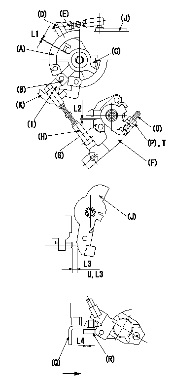
CSD lever assembly adjustment specifications
1. Fixing the side link lever
With the side link levers (A), (B) contacting the stopper (C), adjust the length of the connecting rod (E) so that the clearance between side link lever(D)'s hook and levers (A), (B) is L1.
2. Fixing the M-CSD
With roller holder advanced 0 deg, adjust lever shaft ball pin so that it contacts roller holder. Then adjust position of M-CSD lever F using screw O so that clearance between M-CSD lever F and stopper G is L2. Fix using nut P. Tighten P to torque T.
3. Fixing the CSD lever and the side link lever connecting rod
Move CSD lever (F) through full stroke (until it contacts other stopper). Adjust length of rod (H) connecting side link lever (I) and CSD lever (F) so that position of control lever (J) on top of pump is a (L3) and fix. (Target speed NE.)
4. Fix using the pump supporting bracket
With the bracket Q pushed in the direction of the arrow, set the distance between the bracket Q and the bolt R to L4 and fix using the bolt R.
U = at from idle to A
----------
L1=0.5+1mm L2=0.5+2mm T=6~9N-m(0.6~0.9kgf-m) a=13deg NE=1,900r/min L4=0mm
----------
L1=0.5+-1mm L2=0.5+2mm T=6~9N-m(0.6~0.9kgf-m) L3=8.5+-1mm a=13deg L4=0mm
----------
L1=0.5+1mm L2=0.5+2mm T=6~9N-m(0.6~0.9kgf-m) a=13deg NE=1,900r/min L4=0mm
----------
L1=0.5+-1mm L2=0.5+2mm T=6~9N-m(0.6~0.9kgf-m) L3=8.5+-1mm a=13deg L4=0mm
0000001901 DASHPOT ADJUSTMENT

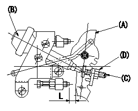
Adjustment of the dash pot
Adjust screw (C) so that the end of screw (C) contacts the end of the dashpot when the control lever (A) is a (clearance L) from the idle position. Then, fix using the nut (D).
(B) = dashpot
----------
L=8.5mm a=13deg
----------
L=8.5mm
----------
L=8.5mm a=13deg
----------
L=8.5mm
Information:
Industrial Rating Definitions
The application examples are listed for reference only. Refer to the specific application information and guidelines within the Technical Marketing Information for exact rating determination.A Rating (Continuous)
* For heavy-duty service when engine is operated at rated load and speed up to 100 percent of the time without interruption or load cycling.* Time at full load up to 100 percent of the duty cycle.* Typical examples are: pipeline pumping, ventilation, and customer specifications.B Rating
* For servicing where power and/or speed are cyclic.* Time at full load not to exceed 80 percent of the duty cycle.* Typical examples are: irrigation where normal pump demand is 85 percent of the duty cycle, oil field mechanical pumping and drilling, and stationary/plant air compressors.C Rating (Intermittent)
* For service where power and/or speed are cyclic* The horsepower and speed capability of the engine can be used for one uninterrupted hour, followed by one hour of operation at or below the A rating.* Time at full load not to exceed 50 percent of the duty cycle.* Typical examples are: agricultural tractors, harvesters and combines, off-highway trucks, fire pump application power, blast hole drills, rock crushers and wood chippers with high torque rise, and oil field hoisting.D Rating
* For service when rated power is required for periodic overloads.* The maximum horsepower and speed capability of the engine can be used for a maximum of 30 uninterrupted minutes, followed by one hour of followed by one hour of C rating operation.* Time at full load not to exceed 10 percent of the duty cycle.* Typical examples are: offshore cranes, runway snow blowers, water well drills, portable air compressors, and fire pump certification power.E Rating
* For service where rated power is required for a short time for initial starting or sudden overload. For emergency service where standard power is unavailable.* The maximum horsepower and speed capability of the engine can be utilized for a maximum of 15 uninterrupted minutes, followed by one hour at C rating operation, or for the duration of the emergency.* Time at full load is not to exceed 5 percent of the duty cycle.* Typical examples are: standby centrifugal water pumps, oil field well servicing, crash trucks, and gas turbine starters.Rating Conditions
Unless otherwise specified, all ratings are based on SAE J1349 standard ambient conditions:* 100 kPa (29.6 inches of Hg) of pressure* 30 percent relative humidity, and* a temperature of 26°C (77°F).Ratings also apply at AS1501, BS5514, DIN6271, and ISO3046/1 standard conditions.Power for diesel engines is based on:* API gravity of 35 at 15°C (60°F),* fuel LHV of 42.780 kJ/g (18390 Btu/lb) at 29°C (84°F), and* fuel density of 838.9 g/L (7.0001 lb/US gal)Ratings are gross output ratings- the total output capability of the engine-equipped with standard accessories. Standard accessories include pumps for lubrication oil, fuel, and jacket water, and magneto as required. The gross output, minus the power required to drive auxiliary components, equals the net power available for the external (flywheel) load. Typical auxiliary components include cooling fans, air compressors,