Information injection-pump assembly
BOSCH
9 460 610 191
9460610191
ZEXEL
104748-0163
1047480163

Rating:
Cross reference number
BOSCH
9 460 610 191
9460610191
ZEXEL
104748-0163
1047480163
Zexel num
Bosch num
Firm num
Name
Calibration Data:
Adjustment conditions
Test oil
1404 Test oil ISO4113orSAEJ967d
1404 Test oil ISO4113orSAEJ967d
Test oil temperature
degC
45
45
50
Nozzle
105000-2010
Bosch type code
NP-DN12SD12TT
Nozzle holder
105780-2080
Opening pressure
MPa
14.7
14.7
15.19
Opening pressure
kgf/cm2
150
150
155
Injection pipe
Inside diameter - outside diameter - length (mm) mm 2-6-840
Inside diameter - outside diameter - length (mm) mm 2-6-840
Transfer pump pressure
kPa
20
20
20
Transfer pump pressure
kgf/cm2
0.2
0.2
0.2
Direction of rotation (viewed from drive side)
Right R
Right R
Injection timing adjustment
Pump speed
r/min
1500
1500
1500
Average injection quantity
mm3/st.
38.7
38.2
39.2
Difference in delivery
mm3/st.
2.5
Basic
*
Injection timing adjustment_02
Pump speed
r/min
2400
2400
2400
Average injection quantity
mm3/st.
13.1
10.1
16.1
Injection timing adjustment_03
Pump speed
r/min
2125
2125
2125
Average injection quantity
mm3/st.
34
32
36
Injection timing adjustment_04
Pump speed
r/min
1500
1500
1500
Average injection quantity
mm3/st.
38.7
37.7
39.7
Injection timing adjustment_05
Pump speed
r/min
500
500
500
Average injection quantity
mm3/st.
32.7
30.7
34.7
Injection quantity adjustment
Pump speed
r/min
2400
2400
2400
Average injection quantity
mm3/st.
13.1
11.1
15.1
Basic
*
Injection quantity adjustment_02
Pump speed
r/min
2550
2550
2550
Average injection quantity
mm3/st.
4
Governor adjustment
Pump speed
r/min
350
350
350
Average injection quantity
mm3/st.
8
6
10
Difference in delivery
mm3/st.
2
Basic
*
Governor adjustment_02
Pump speed
r/min
350
350
350
Average injection quantity
mm3/st.
8
6
10
Timer adjustment
Pump speed
r/min
100
100
100
Average injection quantity
mm3/st.
42
42
Basic
*
Speed control lever angle
Pump speed
r/min
350
350
350
Average injection quantity
mm3/st.
0
0
0
Remarks
Magnet OFF
Magnet OFF
0000000901
Pump speed
r/min
1250
1250
1250
Overflow quantity
cm3/min
430
298
562
Stop lever angle
Pump speed
r/min
1250
1250
1250
Pressure
kPa
510
481
539
Pressure
kgf/cm2
5.2
4.9
5.5
Basic
*
Stop lever angle_02
Pump speed
r/min
500
500
500
Pressure
kPa
294.5
265
324
Pressure
kgf/cm2
3
2.7
3.3
Stop lever angle_03
Pump speed
r/min
1250
1250
1250
Pressure
kPa
510
481
539
Pressure
kgf/cm2
5.2
4.9
5.5
Stop lever angle_04
Pump speed
r/min
1500
1500
1500
Pressure
kPa
578.5
549
608
Pressure
kgf/cm2
5.9
5.6
6.2
Stop lever angle_05
Pump speed
r/min
2125
2125
2125
Pressure
kPa
745.5
716
775
Pressure
kgf/cm2
7.6
7.3
7.9
0000001101
Pump speed
r/min
1250
1250
1250
Timer stroke
mm
3.5
3.3
3.7
Basic
*
_02
Pump speed
r/min
1250
1250
1250
Timer stroke
mm
3.5
3.2
3.8
_03
Pump speed
r/min
1500
1500
1500
Timer stroke
mm
4.7
4.1
5.3
_04
Pump speed
r/min
2125
2125
2125
Timer stroke
mm
7.6
7
8.2
0000001201
Max. applied voltage
V
8
8
8
Test voltage
V
13
12
14
0000001401
Pump speed
r/min
1250
1250
1250
Average injection quantity
mm3/st.
28.2
27.2
29.2
Timer stroke TA
mm
2.7
2.5
2.9
Basic
*
_02
Pump speed
r/min
1250
1250
1250
Average injection quantity
mm3/st.
28.2
26.7
29.7
Timer stroke TA
mm
2.7
2.4
3
_03
Pump speed
r/min
1250
1250
1250
Average injection quantity
mm3/st.
18.1
16.6
19.6
Timer stroke TA
mm
1.5
0.8
2.2
Timing setting
K dimension
mm
3.3
3.2
3.4
KF dimension
mm
5.8
5.7
5.9
MS dimension
mm
1.5
1.4
1.6
Control lever angle alpha
deg.
30
28
32
Control lever angle beta
deg.
45
40
50
Test data Ex:
0000001801 M-CSD ADJUSTMENT
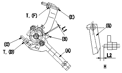
M-CSD adjustment
1. Fixing the M-CSD
(1)At roller holder advance angle a adjust the lever shaft ball pin so that it contacts the roller holder.
(2)At this time, adjust the position of the M-CSD lever (A) using adjusting screw (C) so that the clearance between the M-CSD lever (A) and the stopper (B) becomes L1. Then fix using nut (D).
TT
2. M-FICD adjustment
(1)Move the CSD lever (A) through its full stroke.
(2)Adjust screw (E) so that the control lever (G)'s position is b (the clearance between the control lever and the idling set screw is L2). Then fix using the nut (F).
TT
Pump speed NE
H = from idle to position b
----------
L1=0.5+2mm L2=4.8+-1mm a=0deg b=7deg T=6~9N-m(0.6~0.9kgf-m)
----------
L1=0.5+2mm L2=4.8+-1mm T=6~9N-m(0.6~0.9kgf-m) b=7deg
----------
L1=0.5+2mm L2=4.8+-1mm a=0deg b=7deg T=6~9N-m(0.6~0.9kgf-m)
----------
L1=0.5+2mm L2=4.8+-1mm T=6~9N-m(0.6~0.9kgf-m) b=7deg
0000001901 MICROSWITCH ADJUSTMENT
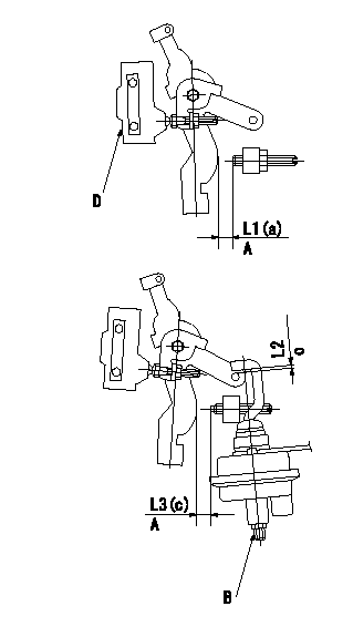
Microswitch adjustment
1. Set the control lever position at a (distance from the idling setscrew is L1).
2. Adjust the lever screw so that the microswitch turns ON and fix using the nut.
Adjustment of the V-FICD
1. V-FICD installation position adjustment
(1)Maintain the control lever position b.
(2)Adjust the position of the bracket so that the clearance between the control lever's roller and the actuator's hook at initial installation is L2. Then, fix using the nut.
2. V-FICD stroke adjustment
(1)Move the actuator through its full stroke.
(2)Adjust the adjusting screw so that the control lever clearance is c (the clearance between the control lever and the idling set screw is L3), then fix using the nut.
(3)Confirm full stroke at P1 {P2}.
A = from idle
B = adjusting screw
C = gap at installation
D = microswitch
----------
a=12.5deg b=0deg c=5deg L1=8.5+-1mm L2=2+2-1mm L3=3.4+-1mm
----------
a=12.5deg c=5deg L1=8.5+-1mm L2=2+2-1mm L3=3.4+-1mm
----------
a=12.5deg b=0deg c=5deg L1=8.5+-1mm L2=2+2-1mm L3=3.4+-1mm
----------
a=12.5deg c=5deg L1=8.5+-1mm L2=2+2-1mm L3=3.4+-1mm
0000002001 FICD BRACKET&CONTROL LEVER
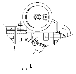
FICD bracket and control lever assembly
L = ensure at least L
----------
----------
L=3 or more mm
----------
----------
L=3 or more mm
Information:
Air Cleaner Indicator
This engine is equipped with an air cleaner mounted service indicator. A colored piston showing in the window indicates the need for servicing the air cleaner. Observe the air cleaner service indicator at regular scheduled intervals. Clean or replace the air cleaner element when the yellow diaphragm enters the red zone or the red piston locks in the visible position.If your air cleaner element becomes plugged, the air can split the element filter material. Unfiltered air will drastically accelerate internal engine wear. Excessive exhaust smoke and/or loss of power may indicate a need for air cleaner element inspection. Perform maintenance on the air cleaner as instructed in this topic.Keep spare filter elements on hand for replacement. The element should be thoroughly checked for rips or tears in the filter material, seal/gasket damage and replaced at least every year or 250 hours.Test Service Indicator
Air cleaner indicators are inexpensive but important instruments which function to show air filter element restriction as the element is progressively filled (plugged) with dust. In average dust conditions, the air cleaner indicators should be tested for proper operation Every 250 Hours . If dust is severe, the indicator should be checked Daily. To test the indicator, perform the following checks.* Check for ease of resetting; should reset in less than a maximum of three pushes.* Check the movement of the yellow core when the engine is accelerated to rated engine speed. The yellow core should latch at or very close to the highest vacuum obtained.If the indicator will NOT reset easily, or the yellow core will not latch at highest vacuum, the indicator(s) should be replaced. If the new indicator will not reset, the indicator sensor hole may be plugged.THE INDICATOR SHOULD BE REPLACED AT OVERHAUL AND/OR MAJOR ENGINE COMPONENT REPLACEMENT. THE INDICATOR MUST BE REPLACED EVERY YEAR REGARDLESS OF OPERATING CONDITIONS. When installing a new indicator, excessive tightening force may crack the top of the indicator. Tighten the indicator to a torque value of 2 N m (18 lb in). Contact your Caterpillar dealer for parts and/or assistance. Clean/Replace Air Cleaner Elements
Never service the air cleaner with the engine running since this will allow dirt to enter the engine. Check the inlet piping for leaks. Make all repairs to inlet piping immediately, as dirt and debris could enter the engine causing damage to the turbocharger and engine components.Clean or replace elements using these recommendations and/or your weather and operating conditions, or when required by the restriction indicator.
1. Remove air cleaner cover and element. Clean or discard used element. Refer to SEBF8062, Guideline for Reusable Parts-Cleaning and Inspection of Air Filters. 2. Cover air inlet opening with a clean cloth or towel to prevent dirt and debris from entering the engine. 3. Clean the inside of the air cleaner cover and body. 4. Remove cloth from air inlet opening and install clean element while noting arrows indicating air flow on the side of the element. 5. Install cover and reset service indicator.Cleaning