Information injection-pump assembly
ZEXEL
104748-0160
1047480160
MAZDA
R20213800
r20213800
Rating:
Cross reference number
ZEXEL
104748-0160
1047480160
MAZDA
R20213800
r20213800
Zexel num
Bosch num
Firm num
Name
Calibration Data:
Adjustment conditions
Test oil
1404 Test oil ISO4113orSAEJ967d
1404 Test oil ISO4113orSAEJ967d
Test oil temperature
degC
45
45
50
Nozzle
105000-2010
Bosch type code
NP-DN12SD12TT
Nozzle holder
105780-2080
Opening pressure
MPa
14.7
14.7
15.19
Opening pressure
kgf/cm2
150
150
155
Injection pipe
Inside diameter - outside diameter - length (mm) mm 2-6-840
Inside diameter - outside diameter - length (mm) mm 2-6-840
Transfer pump pressure
kPa
20
20
20
Transfer pump pressure
kgf/cm2
0.2
0.2
0.2
Direction of rotation (viewed from drive side)
Right R
Right R
Injection timing adjustment
Pump speed
r/min
1250
1250
1250
Average injection quantity
mm3/st.
38.7
38.2
39.2
Difference in delivery
mm3/st.
2.5
Basic
*
Injection timing adjustment_02
Pump speed
r/min
2400
2400
2400
Average injection quantity
mm3/st.
13.1
10.1
16.1
Injection timing adjustment_03
Pump speed
r/min
2300
2300
2300
Average injection quantity
mm3/st.
23
20
26
Injection timing adjustment_04
Pump speed
r/min
2125
2125
2125
Average injection quantity
mm3/st.
33.9
31.9
35.9
Injection timing adjustment_05
Pump speed
r/min
1500
1500
1500
Average injection quantity
mm3/st.
39.6
37.6
41.6
Injection timing adjustment_06
Pump speed
r/min
1250
1250
1250
Average injection quantity
mm3/st.
38.7
37.7
39.7
Injection timing adjustment_07
Pump speed
r/min
500
500
500
Average injection quantity
mm3/st.
33.4
31.4
35.4
Injection quantity adjustment
Pump speed
r/min
2400
2400
2400
Average injection quantity
mm3/st.
13.1
11.1
15.1
Basic
*
Injection quantity adjustment_02
Pump speed
r/min
2500
2500
2500
Average injection quantity
mm3/st.
3
Governor adjustment
Pump speed
r/min
350
350
350
Average injection quantity
mm3/st.
8
6
10
Difference in delivery
mm3/st.
2
Basic
*
Governor adjustment_02
Pump speed
r/min
350
350
350
Average injection quantity
mm3/st.
8
6
10
Timer adjustment
Pump speed
r/min
100
100
100
Average injection quantity
mm3/st.
42
42
Basic
*
Speed control lever angle
Pump speed
r/min
350
350
350
Average injection quantity
mm3/st.
0
0
0
Remarks
Magnet OFF
Magnet OFF
0000000901
Pump speed
r/min
1250
1250
1250
Overflow quantity
cm3/min
430
298
562
Stop lever angle
Pump speed
r/min
1250
1250
1250
Pressure
kPa
510
481
539
Pressure
kgf/cm2
5.2
4.9
5.5
Basic
*
Stop lever angle_02
Pump speed
r/min
500
500
500
Pressure
kPa
294.5
265
324
Pressure
kgf/cm2
3
2.7
3.3
Stop lever angle_03
Pump speed
r/min
1250
1250
1250
Pressure
kPa
510
481
539
Pressure
kgf/cm2
5.2
4.9
5.5
Stop lever angle_04
Pump speed
r/min
2125
2125
2125
Pressure
kPa
745.5
716
775
Pressure
kgf/cm2
7.6
7.3
7.9
0000001101
Pump speed
r/min
1250
1250
1250
Timer stroke
mm
3.9
3.7
4.1
Basic
*
_02
Pump speed
r/min
1250
1250
1250
Timer stroke
mm
3.9
3.6
4.2
_03
Pump speed
r/min
1500
1500
1500
Timer stroke
mm
5.2
4.6
5.8
_04
Pump speed
r/min
2125
2125
2125
Timer stroke
mm
8.8
8.2
9.4
0000001201
Max. applied voltage
V
8
8
8
Test voltage
V
13
12
14
0000001401
Pump speed
r/min
1250
1250
1250
Average injection quantity
mm3/st.
28.2
27.2
29.2
Timer stroke TA
mm
3.1
2.9
3.3
Basic
*
_02
Pump speed
r/min
1250
1250
1250
Average injection quantity
mm3/st.
28
26.5
29.5
Timer stroke TA
mm
3.1
2.8
3.4
_03
Pump speed
r/min
1250
1250
1250
Average injection quantity
mm3/st.
18
16.5
19.5
Timer stroke TA
mm
1.9
1.2
2.6
Timing setting
K dimension
mm
3.3
3.2
3.4
KF dimension
mm
5.8
5.7
5.9
MS dimension
mm
1.5
1.4
1.6
Control lever angle alpha
deg.
30
26
34
Control lever angle beta
deg.
45
40
50
Test data Ex:
0000001801 M-CSD ADJUSTMENT
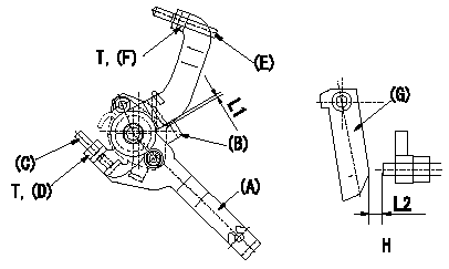
M-CSD adjustment
1. Fixing the M-CSD
(1)At roller holder advance angle a adjust the lever shaft ball pin so that it contacts the roller holder.
(2)At this time, adjust the position of the M-CSD lever (A) using adjusting screw (C) so that the clearance between the M-CSD lever (A) and the stopper (B) becomes L1. Then fix using nut (D).
TT
2. M-FICD adjustment
(1)Move the CSD lever (A) through its full stroke.
(2)Adjust screw (E) so that the control lever (G)'s position is b (the clearance between the control lever and the idling set screw is L2). Then fix using the nut (F).
TT
Pump speed NE
H = from idle to position b
----------
L1=0.5+2mm L2=4.8+-1mm a=0deg b=7deg T=6~9N-m(0.6~0.9kgf-m)
----------
L1=0.5+2mm L2=4.8+-1mm T=6~9N-m(0.6~0.9kgf-m) b=7deg
----------
L1=0.5+2mm L2=4.8+-1mm a=0deg b=7deg T=6~9N-m(0.6~0.9kgf-m)
----------
L1=0.5+2mm L2=4.8+-1mm T=6~9N-m(0.6~0.9kgf-m) b=7deg
0000001901 MICROSWITCH ADJUSTMENT
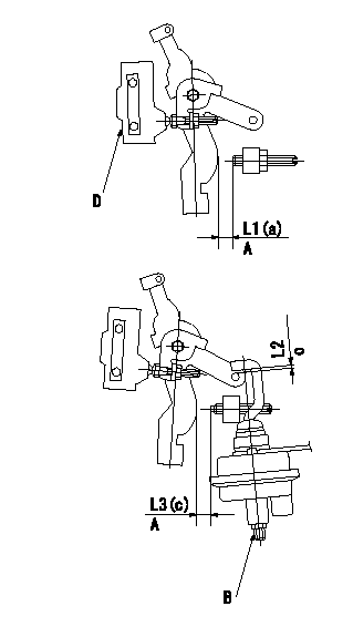
Microswitch adjustment
1. Set the control lever position at a (distance from the idling setscrew is L1).
2. Adjust the lever screw so that the microswitch turns ON and fix using the nut.
Adjustment of the V-FICD
1. V-FICD installation position adjustment
(1)Maintain the control lever position b.
(2)Adjust the position of the bracket so that the clearance between the control lever's roller and the actuator's hook at initial installation is L2. Then, fix using the nut.
2. V-FICD stroke adjustment
(1)Move the actuator through its full stroke.
(2)Adjust the adjusting screw so that the control lever clearance is c (the clearance between the control lever and the idling set screw is L3), then fix using the nut.
(3)Confirm full stroke at P1 {P2}.
A = from idle
B = adjusting screw
C = gap at installation
D = microswitch
----------
a=12.5deg b=0deg c=5deg L1=8.5+-1mm L2=2+2-1mm L3=3.4+-1mm
----------
a=12.5deg c=5deg L1=8.5+-1mm L2=2+2-1mm L3=3.4+-1mm
----------
a=12.5deg b=0deg c=5deg L1=8.5+-1mm L2=2+2-1mm L3=3.4+-1mm
----------
a=12.5deg c=5deg L1=8.5+-1mm L2=2+2-1mm L3=3.4+-1mm
Information:
Caterpillar's Scheduled Oil Sampling (S O S) is the best indicator for determining what is happening inside your engine.S O S is a diagnostic tool designed to identify and measure contamination and condition of oil, oil performance and component wear rates. The program identifies and measures contamination such as soot, sulfur, etc., and the presence of fuel, water and antifreeze in a sample of oil. The tests also determine the amount of wear metals present in the oil sample, which is compared to established Caterpillar norms to determine acceptability.Caterpillar recommends using Scheduled Oil Sampling (S O S), at regularly scheduled intervals, to compliment your preventive maintenance program. To be effective as an indicator, S O S MUST be performed on a continuing basis. Intermittent sampling will NOT allow wear rate trend lines to be established. The Caterpillar Scheduled Oil Sampling Program (S O S), was developed to help Caterpillar users realize the highest possible value from their equipment by minimizing repair costs and maximizing availability. Obtain S O S samples at regularly scheduled intervals to monitor the condition and maintenance requirements of your engine. Consult your Caterpillar dealer for complete information and assistance in establishing an S O S program for your engine(s). Infrared analysis should always be accompanied by wear element analysis and chemical and physical tests to assure accurate diagnosis. Infrared analysis must be used to determine oil change intervals. S O S must include Infrared (IR) in the analysis. S O S Analysis
S O S is composed of three basic tests:* Wear Analysis* Chemical and Physical Tests* Oil Condition Analysis Wear Analysis is performed with an atomic absorption spectrophotometer to monitor component wear rates by identifying and measuring concentrations, in parts per million, of wear elements present in the used oil.Based on known normal concentration data, maximum limits of wear elements are established. Impending failures can be identified when test results deviate from concentration levels established as acceptable, based on normal wear. Through monitoring the used oil, normal component wear trends are determined. Many failures can be identified when wear trends and/or contaminants significantly exceed past trends.Detectable failures are those caused by component wear and gradual contamination from dirt, fuel, water or antifreeze. Wear analysis is not able to predict failures due to component fatigue, sudden loss of lubrication, or sudden ingestion of a large amount of dirt or contaminants since failures of this nature occur too rapidly. Chemical and Physical Tests detect the presence of water, fuel and/or glycol (antifreeze) in the oil and determine whether or not their concentrations exceed established maximum limits. Oil Condition Analysis is evaluated with Infrared Analysis and determines the degree of deterioration of the used oil by measuring the amount of contaminants such as sulfur products, oxidation, nitration products and soot present in the used oil.It also monitors additive depletion and detects ethylene glycol and butyl cellosolve contamination and can assist in customizing (reducing, maintaining or extending) oil change intervals for particular conditions
S O S is composed of three basic tests:* Wear Analysis* Chemical and Physical Tests* Oil Condition Analysis Wear Analysis is performed with an atomic absorption spectrophotometer to monitor component wear rates by identifying and measuring concentrations, in parts per million, of wear elements present in the used oil.Based on known normal concentration data, maximum limits of wear elements are established. Impending failures can be identified when test results deviate from concentration levels established as acceptable, based on normal wear. Through monitoring the used oil, normal component wear trends are determined. Many failures can be identified when wear trends and/or contaminants significantly exceed past trends.Detectable failures are those caused by component wear and gradual contamination from dirt, fuel, water or antifreeze. Wear analysis is not able to predict failures due to component fatigue, sudden loss of lubrication, or sudden ingestion of a large amount of dirt or contaminants since failures of this nature occur too rapidly. Chemical and Physical Tests detect the presence of water, fuel and/or glycol (antifreeze) in the oil and determine whether or not their concentrations exceed established maximum limits. Oil Condition Analysis is evaluated with Infrared Analysis and determines the degree of deterioration of the used oil by measuring the amount of contaminants such as sulfur products, oxidation, nitration products and soot present in the used oil.It also monitors additive depletion and detects ethylene glycol and butyl cellosolve contamination and can assist in customizing (reducing, maintaining or extending) oil change intervals for particular conditions