Information injection-pump assembly
ZEXEL
104748-0153
1047480153

Rating:
Cross reference number
ZEXEL
104748-0153
1047480153
Zexel num
Bosch num
Firm num
Name
104748-0153
DPICO
INJECTION-PUMP ASSEMBLY
R2 Q
R2 Q
Calibration Data:
Adjustment conditions
Test oil
1404 Test oil ISO4113orSAEJ967d
1404 Test oil ISO4113orSAEJ967d
Test oil temperature
degC
45
45
50
Nozzle
105000-2010
Bosch type code
NP-DN12SD12TT
Nozzle holder
105780-2080
Opening pressure
MPa
14.7
14.7
15.19
Opening pressure
kgf/cm2
150
150
155
Injection pipe
Inside diameter - outside diameter - length (mm) mm 2-6-840
Inside diameter - outside diameter - length (mm) mm 2-6-840
Transfer pump pressure
kPa
20
20
20
Transfer pump pressure
kgf/cm2
0.2
0.2
0.2
Direction of rotation (viewed from drive side)
Right R
Right R
Injection timing adjustment
Pump speed
r/min
1500
1500
1500
Average injection quantity
mm3/st.
38.7
38.2
39.2
Difference in delivery
mm3/st.
2.5
Basic
*
Injection timing adjustment_02
Pump speed
r/min
2400
2400
2400
Average injection quantity
mm3/st.
13.1
10.1
16.1
Injection timing adjustment_03
Pump speed
r/min
2125
2125
2125
Average injection quantity
mm3/st.
34
32
36
Injection timing adjustment_04
Pump speed
r/min
1500
1500
1500
Average injection quantity
mm3/st.
38.7
37.7
39.7
Injection timing adjustment_05
Pump speed
r/min
500
500
500
Average injection quantity
mm3/st.
32.7
30.7
34.7
Injection quantity adjustment
Pump speed
r/min
2400
2400
2400
Average injection quantity
mm3/st.
13.1
11.1
15.1
Basic
*
Injection quantity adjustment_02
Pump speed
r/min
2550
2550
2550
Average injection quantity
mm3/st.
4
Governor adjustment
Pump speed
r/min
350
350
350
Average injection quantity
mm3/st.
8
6
10
Difference in delivery
mm3/st.
2
Basic
*
Governor adjustment_02
Pump speed
r/min
350
350
350
Average injection quantity
mm3/st.
8
6
10
Timer adjustment
Pump speed
r/min
100
100
100
Average injection quantity
mm3/st.
42
42
Basic
*
Speed control lever angle
Pump speed
r/min
350
350
350
Average injection quantity
mm3/st.
0
0
0
Remarks
Magnet OFF
Magnet OFF
0000000901
Pump speed
r/min
1250
1250
1250
Overflow quantity
cm3/min
430
298
562
Stop lever angle
Pump speed
r/min
1250
1250
1250
Pressure
kPa
510
481
539
Pressure
kgf/cm2
5.2
4.9
5.5
Basic
*
Stop lever angle_02
Pump speed
r/min
500
500
500
Pressure
kPa
294.5
265
324
Pressure
kgf/cm2
3
2.7
3.3
Stop lever angle_03
Pump speed
r/min
1250
1250
1250
Pressure
kPa
510
481
539
Pressure
kgf/cm2
5.2
4.9
5.5
Stop lever angle_04
Pump speed
r/min
1500
1500
1500
Pressure
kPa
578.5
549
608
Pressure
kgf/cm2
5.9
5.6
6.2
Stop lever angle_05
Pump speed
r/min
2125
2125
2125
Pressure
kPa
745.5
716
775
Pressure
kgf/cm2
7.6
7.3
7.9
0000001101
Pump speed
r/min
1250
1250
1250
Timer stroke
mm
3.5
3.3
3.7
Basic
*
_02
Pump speed
r/min
1250
1250
1250
Timer stroke
mm
3.5
3.2
3.8
_03
Pump speed
r/min
1500
1500
1500
Timer stroke
mm
4.7
4.1
5.3
_04
Pump speed
r/min
2125
2125
2125
Timer stroke
mm
7.6
7
8.2
0000001201
Max. applied voltage
V
8
8
8
Test voltage
V
13
12
14
0000001401
Pump speed
r/min
1250
1250
1250
Average injection quantity
mm3/st.
28.2
27.2
29.2
Timer stroke TA
mm
2.7
2.5
2.9
Basic
*
_02
Pump speed
r/min
1250
1250
1250
Average injection quantity
mm3/st.
28.2
26.7
29.7
Timer stroke TA
mm
2.7
2.4
3
_03
Pump speed
r/min
1250
1250
1250
Average injection quantity
mm3/st.
18.1
16.6
19.6
Timer stroke TA
mm
1.5
0.8
2.2
Timing setting
K dimension
mm
3.3
3.2
3.4
KF dimension
mm
5.8
5.7
5.9
MS dimension
mm
1.5
1.4
1.6
Control lever angle alpha
deg.
30
28
32
Control lever angle beta
deg.
45
40
50
Test data Ex:
0000001801 M-CSD ADJUSTMENT

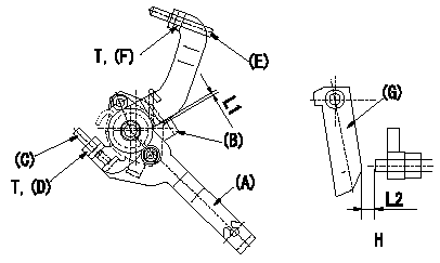
M-CSD adjustment
1. Fixing the M-CSD
(1)At roller holder advance angle a adjust the lever shaft ball pin so that it contacts the roller holder.
(2)At this time, adjust the position of the M-CSD lever (A) using adjusting screw (C) so that the clearance between the M-CSD lever (A) and the stopper (B) becomes L1. Then fix using nut (D).
TT
2. M-FICD adjustment
(1)Move the CSD lever (A) through its full stroke.
(2)Adjust screw (E) so that the control lever (G)'s position is b (the clearance between the control lever and the idling set screw is L2). Then fix using the nut (F).
TT
Pump speed NE
H = from idle to position b
----------
L1=0.5+2mm L2=4.8+-1mm a=0deg b=7deg T=6~9N-m(0.6~0.9kgf-m)
----------
L1=0.5+2mm L2=4.8+-1mm T=6~9N-m(0.6~0.9kgf-m) b=7deg
----------
L1=0.5+2mm L2=4.8+-1mm a=0deg b=7deg T=6~9N-m(0.6~0.9kgf-m)
----------
L1=0.5+2mm L2=4.8+-1mm T=6~9N-m(0.6~0.9kgf-m) b=7deg
Information:
Fuel System Information
Check the fuel level in the tank daily by observing the sight gauge, if equipped.
Fill the fuel tank at the end of each day of operation to drive out moist air and to prevent condensation. Maintain a fairly constant level in the tank (near the top) to avoid drawing moisture into the tank as the level decreases. Do not fill the tank to the top. Fuel expands as it gets warm and may overflow.Drain water and sediment from tank at the interval specified in the Maintenance Schedule.Do not fill fuel filters with fuel before installing them. Contaminated fuel will cause accelerated wear to fuel system parts.
Fuel Recommendations
Use only fuel as recommended in this section. The fuels recommended for use in Caterpillar engines are No.2-D diesel fuel and No.2 fuel oil, although No. 1 grades are acceptable. The following fuel specifications are some of the worldwide fuels which may meet the requirements. Caterpillar Diesel Engines are capable of burning a wide range of distillate fuels. The use of clean, stable blends of distillate fuel which meet the following requirements will provide quality engine service life. Sulfur
The percentage of sulfur in the fuel will affect the engine oil recommendations. Fuel sulfur is chemically changed during combustion to form both sulfurous and sulfuric acid. These acids chemically attack metal surfaces and cause corrosive wear.Certain additives used in lubricating oils contain alkaline compounds that are formulated to neutralize these acids. The measure of this reserve alkalinity in a lubricating oil is known as its Total Base Number (TBN). TBN values are essential to neutralize the acids from combustion gases and to minimize corrosive wear.Fuels containing 0.5% or less sulfur may be used with recommended crankcase oil drain intervals using API CF-4 performance oils. With sulfur above the 0.5% level, use API CF-4 performance oils with an ASTM D-2896 Total Base Number (TBN) of 10 times the fuel sulfur for normal oil drain intervals.Caterpillar recommends infrared analysis (in conjunction with wear metal analysis) of used oil in determining the effectiveness of oil TBN and acid neutralization. The Caterpillar dealer S O S program provides this information. Regular oil analysis (S O S) will provide information to monitor oil properties and engine wear metals to maintain successful engine protection and establish oil drain intervals.Periodically request fuel sulfur content information from your fuel supplier. Fuel sulfur content can change with each bulk delivery. ASTM D-2896 can normally be found at your local technological society, library or college. Any American Petroleum Institute (API) classification performance oil should have sufficient TBN for fuels with less than 0.5% sulfur. Fuels containing 0.5% or less sulfur may be used with recommended crankcase oil drain intervals using API CF-4 performance oils.Additives
Fuel additives are generally not recommended nor needed for the specified fuels listed. Cetane improvers can be used as necessary for the direct injection engine requirements. Biocides may be needed to eliminate microorganism growth in storage tanks. In cold conditions, treatment for entrained water may also
Have questions with 104748-0153?
Group cross 104748-0153 ZEXEL
Mazda
Dpico
104748-0153
INJECTION-PUMP ASSEMBLY
R2
R2