Information injection-pump assembly
ZEXEL
104748-0140
1047480140
MAZDA
RF0213800
rf0213800
Rating:
Cross reference number
ZEXEL
104748-0140
1047480140
MAZDA
RF0213800
rf0213800
Zexel num
Bosch num
Firm num
Name
Calibration Data:
Adjustment conditions
Test oil
1404 Test oil ISO4113orSAEJ967d
1404 Test oil ISO4113orSAEJ967d
Test oil temperature
degC
45
45
50
Nozzle
105000-2010
Bosch type code
NP-DN12SD12TT
Nozzle holder
105780-2080
Opening pressure
MPa
14.7
14.7
15.19
Opening pressure
kgf/cm2
150
150
155
Injection pipe
Inside diameter - outside diameter - length (mm) mm 2-6-840
Inside diameter - outside diameter - length (mm) mm 2-6-840
Transfer pump pressure
kPa
20
20
20
Transfer pump pressure
kgf/cm2
0.2
0.2
0.2
Direction of rotation (viewed from drive side)
Right R
Right R
Injection timing adjustment
Pump speed
r/min
1375
1375
1375
Average injection quantity
mm3/st.
35.8
35.3
36.3
Difference in delivery
mm3/st.
2.5
Basic
*
Injection timing adjustment_02
Pump speed
r/min
2600
2600
2600
Average injection quantity
mm3/st.
11
8
14
Injection timing adjustment_03
Pump speed
r/min
2500
2500
2500
Average injection quantity
mm3/st.
21.1
18.1
24.1
Injection timing adjustment_04
Pump speed
r/min
2325
2325
2325
Average injection quantity
mm3/st.
31.7
29.7
33.7
Injection timing adjustment_05
Pump speed
r/min
1375
1375
1375
Average injection quantity
mm3/st.
35.8
34.8
36.8
Injection timing adjustment_06
Pump speed
r/min
500
500
500
Average injection quantity
mm3/st.
27.9
25.9
29.9
Injection quantity adjustment
Pump speed
r/min
2500
2500
2500
Average injection quantity
mm3/st.
21.1
19.1
23.1
Basic
*
Injection quantity adjustment_02
Pump speed
r/min
2700
2700
2700
Average injection quantity
mm3/st.
4
Governor adjustment
Pump speed
r/min
350
350
350
Average injection quantity
mm3/st.
8
6
10
Difference in delivery
mm3/st.
2
Basic
*
Governor adjustment_02
Pump speed
r/min
350
350
350
Average injection quantity
mm3/st.
8
6
10
Governor adjustment_03
Pump speed
r/min
450
450
450
Average injection quantity
mm3/st.
3
Timer adjustment
Pump speed
r/min
100
100
100
Average injection quantity
mm3/st.
42
42
Basic
*
Speed control lever angle
Pump speed
r/min
350
350
350
Average injection quantity
mm3/st.
0
0
0
Remarks
Magnet OFF
Magnet OFF
0000000901
Pump speed
r/min
1375
1375
1375
Overflow quantity
cm3/min
410
278
542
Stop lever angle
Pump speed
r/min
1375
1375
1375
Pressure
kPa
460.5
431
490
Pressure
kgf/cm2
4.7
4.4
5
Basic
*
Stop lever angle_02
Pump speed
r/min
500
500
500
Pressure
kPa
215.5
186
245
Pressure
kgf/cm2
2.2
1.9
2.5
Stop lever angle_03
Pump speed
r/min
1375
1375
1375
Pressure
kPa
460.5
431
490
Pressure
kgf/cm2
4.7
4.4
5
Stop lever angle_04
Pump speed
r/min
2325
2325
2325
Pressure
kPa
706
677
735
Pressure
kgf/cm2
7.2
6.9
7.5
0000001101
Pump speed
r/min
1375
1375
1375
Timer stroke
mm
4.7
4.5
4.9
Basic
*
_02
Pump speed
r/min
1375
1375
1375
Timer stroke
mm
4.7
4.4
5
_03
Pump speed
r/min
2000
2000
2000
Timer stroke
mm
8
7.4
8.6
_04
Pump speed
r/min
2325
2325
2325
Timer stroke
mm
9.7
9.1
10.3
0000001201
Max. applied voltage
V
8
8
8
Test voltage
V
13
12
14
0000001401
Pump speed
r/min
1375
1375
1375
Average injection quantity
mm3/st.
28.2
27.2
29.2
Timer stroke TA
mm
4.1
3.9
4.3
Basic
*
_02
Pump speed
r/min
1375
1375
1375
Average injection quantity
mm3/st.
28
26.5
29.5
Timer stroke TA
mm
4.1
3.8
4.4
_03
Pump speed
r/min
1375
1375
1375
Average injection quantity
mm3/st.
16
14.5
17.5
Timer stroke TA
mm
2.9
2.2
3.6
Timing setting
K dimension
mm
3.3
3.2
3.4
KF dimension
mm
5.8
5.7
5.9
MS dimension
mm
1.5
1.4
1.6
Control lever angle alpha
deg.
30
26
34
Control lever angle beta
deg.
45
40
50
Test data Ex:
0000001801 M-CSD ADJUSTMENT
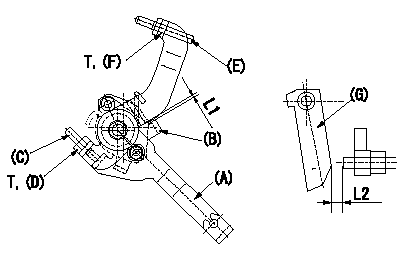
M-CSD adjustment
1. Fixing the M-CSD
(1)At roller holder advance angle a adjust the lever shaft ball pin so that it contacts the roller holder.
(2)At this time, adjust the position of the M-CSD lever (A) using adjusting screw (C) so that the clearance between the M-CSD lever (A) and the stopper (B) becomes L1. Then fix using nut (D).
2. M-FICD adjustment
(1)Move the CSD lever (A) through its full stroke.
(2)Adjust screw (E) so that the control lever (G)'s position is b (the clearance between the control lever and the idling set screw is L2). Then fix using the nut (F).
----------
L1=0.5+2mm L2=4.8+-1mm a=0deg b=7deg
----------
L1=0.5+2mm L2=4.8+-1mm T=-N-m(-kgf-m) b=7deg
----------
L1=0.5+2mm L2=4.8+-1mm a=0deg b=7deg
----------
L1=0.5+2mm L2=4.8+-1mm T=-N-m(-kgf-m) b=7deg
0000001901 MICROSWITCH ADJUSTMENT
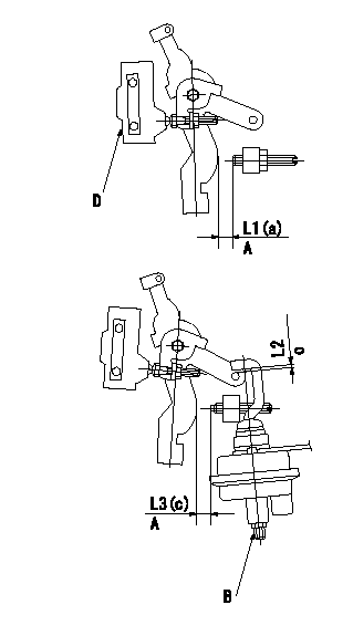
Microswitch adjustment
1. Set the control lever position at a (distance from the idling setscrew is L1).
2. Adjust the lever screw so that the microswitch turns ON and fix using the nut.
Adjustment of the V-FICD
1. V-FICD installation position adjustment
(1)Maintain the control lever position b.
(2)Adjust the position of the bracket so that the clearance between the control lever's roller and the actuator's hook at initial installation is L2. Then, fix using the nut.
2. V-FICD stroke adjustment
(1)Move the actuator through its full stroke.
(2)Adjust the adjusting screw so that the control lever clearance is c (the clearance between the control lever and the idling set screw is L3), then fix using the nut.
(3)Confirm full stroke at P1 {P2}.
A = from idle
B = adjusting screw
C = gap at installation
D = microswitch
----------
a=12.5deg b=0deg c=5deg L1=8.5+-1mm L2=2+2-1mm L3=3.4+-1mm
----------
a=12.5deg c=5deg L1=8.5+-1mm L2=2+2-1mm L3=3.4+-1mm
----------
a=12.5deg b=0deg c=5deg L1=8.5+-1mm L2=2+2-1mm L3=3.4+-1mm
----------
a=12.5deg c=5deg L1=8.5+-1mm L2=2+2-1mm L3=3.4+-1mm
Information:
Cleaning Air Filter Elements
The primary element (Caterpillar air filters) can be cleaned several times before replacement. The element, when cleaned, should be thoroughly checked for rips or tears in the filter material.Replace the primary element at least every year regardless of the number of operating hours the element has accumulated.
Do not clean filter elements by bumping or tapping.Do not use filter elements with damaged pleats, gaskets or seals. Engine damage could result.
Filter elements can be cleaned with air pressure, 205 kPa (30 psi) maximum, or water pressure, 280 kPa (40 psi) maximum, or detergent washing. Have spare elements on hand to use while cleaning used elements.* Direct air or water along the length of the pleats inside and outside of filter element. The element can be washed in warm water and nonsudsing household detergent, such as automatic dishwasher detergent. Rinse inside and outside the pleats. The filter should then be thoroughly air dried and inspected. * Inspect the filter elements after cleaning for any rips, tears or damage. Insert a light inside of the clean, dry element. Do not use a filter element with damaged pleats, gaskets or seals. Discard the element if damaged. * Wrap and store the clean filter elements in a clean, dry place.For more information on air cleaner element cleaning, refer to SEBF8062, Guideline for Reusable Parts-Cleaning and Inspection of Air Filters.Belts
Check/Adjust
Inspect the condition and adjustment of alternator and accessory drive belts. Examine all drive belts for wear and replace if they show any signs of wear. Loose or worn pulley grooves cause belt slippage and low accessory drive speed. If belts are too loose, they vibrate enough to cause unnecessary wear on the belts and pulleys and possibly slip enough to cause overheating.If belts are too tight, unnecessary stresses are placed upon the pulley bearings and belts which might shorten the life of both.If one belt in a set requires replacement, always install a new matched set of belts. Never replace just the worn belt. If only the worn belt is replaced, the new belt will carry all the load, as it will not be stretched as much as the older belts. All the belts will fail in rapid succession.Remove the belt guard. Inspect the condition and adjustment of alternator belts and accessory drive belts (if equipped).To check the belt tension, apply 110 Newton (25 lb) force, perpendicular to the belt, midway between the driving and driven pulley. Measure the belt deflection. Correctly adjusted belts will deflect 15 to 20 mm (9/16 to 7/8 inch).If the belt does not require replacement or adjustment, install the belt guard. If the belt requires adjustment or replacement, perform the following procedure to adjust the belt tension.
Typical belt assembly mounting bolt (1) and adjusting nuts (2).1. Loosen the mounting bolt (1) and the locknut on the adjusting bolt.2. Turn the adjusting nuts (2) to increase or decrease the belt tension.3. Tighten the adjusting bolt locknut. Tighten the mounting bolts. Refer to the Torque Specifications in