Information injection-pump assembly
BOSCH
9 460 610 143
9460610143
ZEXEL
104748-0133
1047480133
MAZDA
RF0113800C
rf0113800c
Rating:
Cross reference number
BOSCH
9 460 610 143
9460610143
ZEXEL
104748-0133
1047480133
MAZDA
RF0113800C
rf0113800c
Zexel num
Bosch num
Firm num
Name
Calibration Data:
Adjustment conditions
Test oil
1404 Test oil ISO4113orSAEJ967d
1404 Test oil ISO4113orSAEJ967d
Test oil temperature
degC
45
45
50
Nozzle
105000-2010
Bosch type code
NP-DN12SD12TT
Nozzle holder
105780-2080
Opening pressure
MPa
14.7
14.7
15.19
Opening pressure
kgf/cm2
150
150
155
Injection pipe
Inside diameter - outside diameter - length (mm) mm 2-6-840
Inside diameter - outside diameter - length (mm) mm 2-6-840
Transfer pump pressure
kPa
20
20
20
Transfer pump pressure
kgf/cm2
0.2
0.2
0.2
Direction of rotation (viewed from drive side)
Right R
Right R
Injection timing adjustment
Pump speed
r/min
1375
1375
1375
Average injection quantity
mm3/st.
36.1
35.6
36.6
Difference in delivery
mm3/st.
2.5
Basic
*
Injection timing adjustment_02
Pump speed
r/min
2500
2500
2500
Average injection quantity
mm3/st.
21.1
18.1
24.1
Injection timing adjustment_03
Pump speed
r/min
2325
2325
2325
Average injection quantity
mm3/st.
31.7
29.7
33.7
Injection timing adjustment_04
Pump speed
r/min
1375
1375
1375
Average injection quantity
mm3/st.
36.1
35.1
37.1
Injection timing adjustment_05
Pump speed
r/min
500
500
500
Average injection quantity
mm3/st.
29.5
27.5
31.5
Injection quantity adjustment
Pump speed
r/min
2500
2500
2500
Average injection quantity
mm3/st.
21.1
19.1
23.1
Basic
*
Injection quantity adjustment_02
Pump speed
r/min
2750
2750
2750
Average injection quantity
mm3/st.
4
Governor adjustment
Pump speed
r/min
350
350
350
Average injection quantity
mm3/st.
8
6
10
Difference in delivery
mm3/st.
2
Basic
*
Governor adjustment_02
Pump speed
r/min
350
350
350
Average injection quantity
mm3/st.
8
6
10
Governor adjustment_03
Pump speed
r/min
450
450
450
Average injection quantity
mm3/st.
4
Timer adjustment
Pump speed
r/min
100
100
100
Average injection quantity
mm3/st.
42
42
Basic
*
Speed control lever angle
Pump speed
r/min
350
350
350
Average injection quantity
mm3/st.
0
0
0
Remarks
Magnet OFF
Magnet OFF
0000000901
Pump speed
r/min
1375
1375
1375
Overflow quantity
cm3/min
410
278
542
Stop lever angle
Pump speed
r/min
1375
1375
1375
Pressure
kPa
460.5
431
490
Pressure
kgf/cm2
4.7
4.4
5
Basic
*
Stop lever angle_02
Pump speed
r/min
500
500
500
Pressure
kPa
215.5
186
245
Pressure
kgf/cm2
2.2
1.9
2.5
Stop lever angle_03
Pump speed
r/min
1375
1375
1375
Pressure
kPa
460.5
431
490
Pressure
kgf/cm2
4.7
4.4
5
Stop lever angle_04
Pump speed
r/min
2325
2325
2325
Pressure
kPa
706
677
735
Pressure
kgf/cm2
7.2
6.9
7.5
0000001101
Pump speed
r/min
1375
1375
1375
Timer stroke
mm
4.7
4.5
4.9
Basic
*
_02
Pump speed
r/min
1375
1375
1375
Timer stroke
mm
4.7
4.4
5
_03
Pump speed
r/min
2000
2000
2000
Timer stroke
mm
8
7.4
8.6
_04
Pump speed
r/min
2325
2325
2325
Timer stroke
mm
9.7
9.1
10.3
0000001201
Max. applied voltage
V
8
8
8
Test voltage
V
13
12
14
0000001401
Pump speed
r/min
1375
1375
1375
Average injection quantity
mm3/st.
28.2
27.2
29.2
Timer stroke TA
mm
4.1
3.9
4.3
Basic
*
_02
Pump speed
r/min
1375
1375
1375
Average injection quantity
mm3/st.
28.2
26.7
29.7
Timer stroke TA
mm
4.1
3.8
4.4
_03
Pump speed
r/min
1375
1375
1375
Average injection quantity
mm3/st.
16.1
14.6
17.6
Timer stroke TA
mm
2.9
2.2
3.6
Timing setting
K dimension
mm
3.3
3.2
3.4
KF dimension
mm
5.8
5.7
5.9
MS dimension
mm
1.5
1.4
1.6
Control lever angle alpha
deg.
30
26
34
Control lever angle beta
deg.
45
40
50
Test data Ex:
0000001801 M-CSD ADJUSTMENT
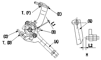
M-CSD adjustment
1. Fixing the M-CSD
(1)At roller holder advance angle a adjust the lever shaft ball pin so that it contacts the roller holder.
(2)At this time, adjust the position of the M-CSD lever (A) using adjusting screw (C) so that the clearance between the M-CSD lever (A) and the stopper (B) becomes L1. Then fix using nut (D).
TT
2. M-FICD adjustment
(1)Move the CSD lever (A) through its full stroke.
(2)Adjust screw (E) so that the control lever (G)'s position is b (the clearance between the control lever and the idling set screw is L2). Then fix using the nut (F).
TT
Pump speed NE
H = from idle to position b
----------
L1=0.5+2mm L2=4.8+-1mm a=0deg b=7deg T=6~9N-m(0.6~0.9kgf-m)
----------
L1=0.5+2mm L2=4.8+-1mm T=6~9N-m(0.6~0.9kgf-m) b=7deg
----------
L1=0.5+2mm L2=4.8+-1mm a=0deg b=7deg T=6~9N-m(0.6~0.9kgf-m)
----------
L1=0.5+2mm L2=4.8+-1mm T=6~9N-m(0.6~0.9kgf-m) b=7deg
Information:
Coolant is essential to control engine operating temperatures and make components last longer. Poorly maintained coolant can actually shorten component life by causing a chain reaction of heat problems. Excessive heat can cause: * Hot spots that crack steel, notably in cylinder heads* Bubble pockets that form on cylinder surfaces and result in liner pitting* Oil to degrade, leading to component damage* Lacquer and shellac build-up on precision hydraulic parts* Oil additives to break down and transmission clutches to slipS O S Coolant Analysis is the best way to monitor the condition of your coolant and your cooling system. The two-level program, based on samples you submit, shows the condition of coolant and the cooling system.Level I: Basic Coolant Maintenance Check
Checks for correct chemical balance for proper heat and corrosion control. Tests for: * glycol* SCA concentrations* pH* conductivityS O S Coolant Analysis reports results and makes recommendations, usually within 24 hours. Consult with your Caterpillar dealer for more information.The concentration of SCA should be checked regularly for over or under concentration. This should be done with the 4C-9301 Test Kit or the 8T-5296 Test Kit or S O S Coolant Analysis (Level I) at the Every 250 Hours interval.Further coolant analysis is recommended at twice a year or after every 1000 service hours.For example, suppose considerable deposits are found in the water jacket areas on the external cooling system, yet coolant additive concentrations were carefully maintained. Chances are that the coolant water had minerals which deposited on the engine over time.One way to verify the water condition, or to be sure of new water at fill time, is to have a coolant analysis conducted. Full water analysis can sometimes be obtained locally by contacting your local water utility company or an agricultural agent. Private laboratories are also available.Caterpillar recommends S O S Level II Coolant Analysis.Level II: Comprehensive Cooling System Analysis
Completely analyzes coolant and coolant effects on the cooling system. Level II Coolant Analysis provides: * full Level I analysis* visual properties inspection* metal corrosion and contaminant identification* identification of built-up impurities that point to corrosion and scaling problems BEFORE they lead to costly repairsLevel II Coolant Analysis provides a simple, clear report of results, and makes recommendations for the lowest cost corrective options.For more information on coolant analysis and how it can help you manage your equipment, see your Caterpillar dealer.