Information injection-pump assembly
ZEXEL
104748-0130
1047480130
MAZDA
RF0113800
rf0113800

Rating:
Cross reference number
ZEXEL
104748-0130
1047480130
MAZDA
RF0113800
rf0113800
Zexel num
Bosch num
Firm num
Name
Calibration Data:
Adjustment conditions
Test oil
1404 Test oil ISO4113orSAEJ967d
1404 Test oil ISO4113orSAEJ967d
Test oil temperature
degC
45
45
50
Nozzle
105000-2010
Bosch type code
NP-DN12SD12TT
Nozzle holder
105780-2080
Opening pressure
MPa
14.7
14.7
15.19
Opening pressure
kgf/cm2
150
150
155
Injection pipe
Inside diameter - outside diameter - length (mm) mm 2-6-840
Inside diameter - outside diameter - length (mm) mm 2-6-840
Transfer pump pressure
kPa
20
20
20
Transfer pump pressure
kgf/cm2
0.2
0.2
0.2
Direction of rotation (viewed from drive side)
Right R
Right R
Injection timing adjustment
Pump speed
r/min
1375
1375
1375
Average injection quantity
mm3/st.
35.8
35.3
36.3
Difference in delivery
mm3/st.
2.5
Basic
*
Injection timing adjustment_02
Pump speed
r/min
2600
2600
2600
Average injection quantity
mm3/st.
11
8
14
Injection timing adjustment_03
Pump speed
r/min
2500
2500
2500
Average injection quantity
mm3/st.
21.1
18.1
24.1
Injection timing adjustment_04
Pump speed
r/min
2325
2325
2325
Average injection quantity
mm3/st.
31.7
29.7
33.7
Injection timing adjustment_05
Pump speed
r/min
1375
1375
1375
Average injection quantity
mm3/st.
35.8
34.8
36.8
Injection timing adjustment_06
Pump speed
r/min
500
500
500
Average injection quantity
mm3/st.
27.9
25.9
29.9
Injection quantity adjustment
Pump speed
r/min
2500
2500
2500
Average injection quantity
mm3/st.
21.1
19.1
23.1
Basic
*
Injection quantity adjustment_02
Pump speed
r/min
2700
2700
2700
Average injection quantity
mm3/st.
4
Governor adjustment
Pump speed
r/min
350
350
350
Average injection quantity
mm3/st.
8
6
10
Difference in delivery
mm3/st.
2
Basic
*
Governor adjustment_02
Pump speed
r/min
350
350
350
Average injection quantity
mm3/st.
8
6
10
Governor adjustment_03
Pump speed
r/min
450
450
450
Average injection quantity
mm3/st.
3
Timer adjustment
Pump speed
r/min
100
100
100
Average injection quantity
mm3/st.
42
42
Basic
*
Speed control lever angle
Pump speed
r/min
350
350
350
Average injection quantity
mm3/st.
0
0
0
Remarks
Magnet OFF
Magnet OFF
0000000901
Pump speed
r/min
1375
1375
1375
Overflow quantity
cm3/min
410
278
542
Stop lever angle
Pump speed
r/min
1375
1375
1375
Pressure
kPa
460.5
431
490
Pressure
kgf/cm2
4.7
4.4
5
Basic
*
Stop lever angle_02
Pump speed
r/min
500
500
500
Pressure
kPa
215.5
186
245
Pressure
kgf/cm2
2.2
1.9
2.5
Stop lever angle_03
Pump speed
r/min
1375
1375
1375
Pressure
kPa
460.5
431
490
Pressure
kgf/cm2
4.7
4.4
5
Stop lever angle_04
Pump speed
r/min
2325
2325
2325
Pressure
kPa
706
677
735
Pressure
kgf/cm2
7.2
6.9
7.5
0000001101
Pump speed
r/min
1375
1375
1375
Timer stroke
mm
4.7
4.5
4.9
Basic
*
_02
Pump speed
r/min
1375
1375
1375
Timer stroke
mm
4.7
4.4
5
_03
Pump speed
r/min
2000
2000
2000
Timer stroke
mm
8
7.4
8.6
_04
Pump speed
r/min
2325
2325
2325
Timer stroke
mm
9.7
9.1
10.3
0000001201
Max. applied voltage
V
8
8
8
Test voltage
V
13
12
14
0000001401
Pump speed
r/min
1375
1375
1375
Average injection quantity
mm3/st.
28.2
27.2
29.2
Timer stroke TA
mm
4.1
3.9
4.3
Basic
*
_02
Pump speed
r/min
1375
1375
1375
Average injection quantity
mm3/st.
28
26.5
29.5
Timer stroke TA
mm
4.1
3.8
4.4
_03
Pump speed
r/min
1375
1375
1375
Average injection quantity
mm3/st.
16
14.5
17.5
Timer stroke TA
mm
2.9
2.2
3.6
Timing setting
K dimension
mm
3.3
3.2
3.4
KF dimension
mm
5.8
5.7
5.9
MS dimension
mm
1.5
1.4
1.6
Control lever angle alpha
deg.
30
26
34
Control lever angle beta
deg.
45
40
50
Test data Ex:
0000001801 M-CSD ADJUSTMENT
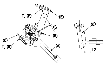
M-CSD adjustment
1. Fixing the M-CSD
(1)At roller holder advance angle a adjust the lever shaft ball pin so that it contacts the roller holder.
(2)At this time, adjust the position of the M-CSD lever (A) using adjusting screw (C) so that the clearance between the M-CSD lever (A) and the stopper (B) becomes L1. Then fix using nut (D).
2. M-FICD adjustment
(1)Move the CSD lever (A) through its full stroke.
(2)Adjust screw (E) so that the control lever (G)'s position is b (the clearance between the control lever and the idling set screw is L2). Then fix using the nut (F).
----------
L1=0.5+2mm L2=4.8+-1mm a=0deg b=7deg
----------
L1=0.5+2mm L2=4.8+-1mm T=-N-m(-kgf-m) b=7deg
----------
L1=0.5+2mm L2=4.8+-1mm a=0deg b=7deg
----------
L1=0.5+2mm L2=4.8+-1mm T=-N-m(-kgf-m) b=7deg
Information:
ELC cooling systems can withstand contamination of up to ten percent of conventional HD coolant/antifreeze. If the contamination exceeds ten percent of the total system capacity, perform either one of the following two procedures:* Drain the cooling system. Flush the system with clean water. Refill the system with ELC.* Maintain the cooling system as if the system is filled with conventional HD coolant/antifreeze.Commercial Extended Life Coolant
If Caterpillar extended life coolant is not used, select a commercial extended life coolant that meets the Caterpillar EC-1 specification. Do not use a product that is labeled as an extended life coolant but does not meet the Caterpillar EC-1 specification. Follow the coolant maintenance guidelines of the commercial extended life coolant supplier. In all cases, use distilled or deionized water or use water that has the properties listed in the Caterpillar Water Quality Limits chart.Caterpillar Diesel Engine Antifreeze/Coolant (DEAC)
For cooling systems using conventional HD coolant, Caterpillar recommends the use of Caterpillar Diesel Engine Antifreeze/Coolant (DEAC). DEAC is an alkaline type, single-phase, ethylene glycol-based antifreeze/coolant. DEAC contains inorganic corrosion inhibitors and anti-foaming agents.Contact your Caterpillar dealer for part numbers and available container sizes.Caterpillar DEAC is available premixed with distilled water in a 50/50 concentration. If DEAC concentrate is used, Caterpillar recommends mixing the concentrate with distilled or deionized water. If distilled or deionized water is not available, use water that has the properties listed in the Caterpillar Water Quality Limits chart.Caterpillar Supplemental Coolant Additive (SCA)
Caterpillar Supplemental Coolant Additive (SCA) is effective in preventing corrosion on all metals. Caterpillar SCA also prevents the formation of mineral deposits, prevents liner cavitation, and eliminates coolant foaming.Caterpillar DEAC is formulated with the correct level of Caterpillar SCA. Additional SCA is NOT needed when the cooling system is initially filled with DEAC.Contact your Caterpillar dealer for part numbers and available container sizes.Commercial Heavy Duty (HD) Coolant/Antifreeze and SCA
If Caterpillar DEAC is not used, select a low silicate commercial HD coolant/antifreeze that meets ASTM D5345 or D4985 specifications.When a commercial HD coolant/antifreeze is used, the cooling system should be treated with three to six percent Caterpillar SCA by volume. Refer to the Caterpillar SCA Requirements for Heavy Duty Coolant/Antifreeze chart. If Caterpillar SCA is not used, select a commercial SCA. The commercial SCA must provide a minimum of 1200 mg/L or 1200 ppm (70 grains/US gal) nitrites in the final coolant mixture. Follow the coolant maintenance guidelines of the commercial SCA supplier.HD coolant/antifreezes that meet ASTM D5345 or D4985 specifications DO require SCA treatment at initial fill, and on a maintenance basis.When mixing concentrated coolants, use distilled or deionized water or use water that has the properties listed in the Caterpillar Water Quality Limits chart.Heavy Duty Coolant/Antifreeze Cooling System Maintenance
Never operate an engine without thermostats in the cooling system. Thermostats maintain the engine coolant at the proper operating temperature. Cooling system problems can develop without thermostats.
Check the coolant/antifreeze solution (glycol content) frequently to ensure adequate anti-boil and anti-freeze protection. Caterpillar recommends the use of a refractometer for checking the