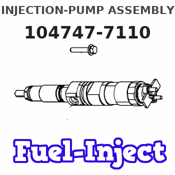
Information injection-pump assembly
ZEXEL
104747-7110
1047477110
KOMATSU
6273711140
6273711140
Rating:
Cross reference number
ZEXEL
104747-7110
1047477110
KOMATSU
6273711140
6273711140
Zexel num
Bosch num
Firm num
Name
104747-7110
6273711140 KOMATSU
INJECTION-PUMP ASSEMBLY
S4D95LWE-
S4D95LWE-
Calibration Data:
Adjustment conditions
Test oil
1404 Test oil ISO4113orSAEJ967d
1404 Test oil ISO4113orSAEJ967d
Test oil temperature
degC
45
45
50
Nozzle
105780-0060
Bosch type code
NP-DN0SD1510
Nozzle holder
105780-2150
Opening pressure
MPa
13
13
13.3
Opening pressure
kgf/cm2
133
133
136
Injection pipe
157805-7320
Injection pipe
Inside diameter - outside diameter - length (mm) mm 2-6-450
Inside diameter - outside diameter - length (mm) mm 2-6-450
Joint assembly
157641-4720
Tube assembly
157641-4020
Transfer pump pressure
kPa
20
20
20
Transfer pump pressure
kgf/cm2
0.2
0.2
0.2
Direction of rotation (viewed from drive side)
Right R
Right R
Injection timing adjustment
Pump speed
r/min
500
500
500
Boost pressure
kPa
0
0
0
Boost pressure
mmHg
0
0
0
Average injection quantity
mm3/st.
56.1
55.6
56.6
Basic
*
Oil temperature
degC
48
46
50
Remarks
NA
NA
Injection timing adjustment_02
Pump speed
r/min
800
800
800
Boost pressure
kPa
18.7
17.4
20
Boost pressure
mmHg
140
130
150
Average injection quantity
mm3/st.
64.1
63.6
64.6
Basic
*
Oil temperature
degC
50
48
52
Remarks
CBS
CBS
Injection timing adjustment_03
Pump speed
r/min
800
800
800
Boost pressure
kPa
40
38.7
41.3
Boost pressure
mmHg
300
290
310
Average injection quantity
mm3/st.
66.8
66.3
67.3
Difference in delivery
mm3/st.
5
Basic
*
Oil temperature
degC
50
48
52
Remarks
Full
Full
Injection timing adjustment_04
Pump speed
r/min
500
500
500
Boost pressure
kPa
0
0
0
Boost pressure
mmHg
0
0
0
Average injection quantity
mm3/st.
56.1
55.1
57.1
Basic
*
Oil temperature
degC
48
46
50
Remarks
NA
NA
Injection timing adjustment_05
Pump speed
r/min
800
800
800
Boost pressure
kPa
18.7
17.4
20
Boost pressure
mmHg
140
130
150
Average injection quantity
mm3/st.
64.1
63.1
65.1
Basic
*
Oil temperature
degC
50
48
52
Remarks
CBS
CBS
Injection timing adjustment_06
Pump speed
r/min
800
800
800
Boost pressure
kPa
40
38.7
41.3
Boost pressure
mmHg
300
290
310
Average injection quantity
mm3/st.
66.8
65.8
67.8
Difference in delivery
mm3/st.
5.5
Basic
*
Oil temperature
degC
50
48
52
Remarks
Full
Full
Injection timing adjustment_07
Pump speed
r/min
1300
1300
1300
Boost pressure
kPa
40
38.7
41.3
Boost pressure
mmHg
300
290
310
Average injection quantity
mm3/st.
58
53.5
62.5
Oil temperature
degC
50
48
52
Injection quantity adjustment
Pump speed
r/min
1425
1425
1425
Boost pressure
kPa
40
38.7
41.3
Boost pressure
mmHg
300
290
310
Average injection quantity
mm3/st.
31.3
28.3
34.3
Difference in delivery
mm3/st.
9
Basic
*
Oil temperature
degC
50
48
52
Injection quantity adjustment_02
Pump speed
r/min
1600
1600
1600
Boost pressure
kPa
40
38.7
41.3
Boost pressure
mmHg
300
290
310
Average injection quantity
mm3/st.
3
Oil temperature
degC
50
48
52
Injection quantity adjustment_03
Pump speed
r/min
1425
1425
1425
Boost pressure
kPa
40
38.7
41.3
Boost pressure
mmHg
300
290
310
Average injection quantity
mm3/st.
31.3
26.8
35.8
Basic
*
Oil temperature
degC
50
48
52
Governor adjustment
Pump speed
r/min
400
400
400
Boost pressure
kPa
0
0
0
Boost pressure
mmHg
0
0
0
Average injection quantity
mm3/st.
16.1
14.1
18.1
Difference in delivery
mm3/st.
3
Basic
*
Oil temperature
degC
48
46
50
Governor adjustment_02
Pump speed
r/min
350
350
350
Boost pressure
kPa
0
0
0
Boost pressure
mmHg
0
0
0
Average injection quantity
mm3/st.
30.5
23.5
37.5
Oil temperature
degC
48
46
50
Governor adjustment_03
Pump speed
r/min
400
400
400
Boost pressure
kPa
0
0
0
Boost pressure
mmHg
0
0
0
Average injection quantity
mm3/st.
16.1
13.6
18.6
Difference in delivery
mm3/st.
3.5
Basic
*
Oil temperature
degC
48
46
50
Timer adjustment
Pump speed
r/min
100
100
100
Boost pressure
kPa
0
0
0
Boost pressure
mmHg
0
0
0
Average injection quantity
mm3/st.
80
75
85
Basic
*
Oil temperature
degC
48
46
50
Remarks
IDLE
IDLE
Timer adjustment_02
Pump speed
r/min
100
100
100
Boost pressure
kPa
0
0
0
Boost pressure
mmHg
0
0
0
Average injection quantity
mm3/st.
80
75
85
Oil temperature
degC
48
46
50
Remarks
IDLE
IDLE
Speed control lever angle
Pump speed
r/min
400
400
400
Boost pressure
kPa
0
0
0
Boost pressure
mmHg
0
0
0
Average injection quantity
mm3/st.
0
0
0
Oil temperature
degC
48
46
50
Remarks
Magnet OFF at idling position
Magnet OFF at idling position
0000000901
Pump speed
r/min
1300
1300
1300
Boost pressure
kPa
40
38.7
41.3
Boost pressure
mmHg
300
290
310
Overflow quantity
cm3/min
430
300
560
Oil temperature
degC
50
48
52
Stop lever angle
Pump speed
r/min
1300
1300
1300
Boost pressure
kPa
40
38.7
41.3
Boost pressure
mmHg
300
290
310
Pressure
kPa
559
539
579
Pressure
kgf/cm2
5.7
5.5
5.9
Basic
*
Oil temperature
degC
50
48
52
Stop lever angle_02
Pump speed
r/min
800
800
800
Boost pressure
kPa
40
38.7
41.3
Boost pressure
mmHg
300
290
310
Pressure
kPa
422
373
471
Pressure
kgf/cm2
4.3
3.8
4.8
Oil temperature
degC
50
48
52
Stop lever angle_03
Pump speed
r/min
900
900
900
Boost pressure
kPa
40
38.7
41.3
Boost pressure
mmHg
300
290
310
Pressure
kPa
441
392
490
Pressure
kgf/cm2
4.5
4
5
Oil temperature
degC
50
48
52
Stop lever angle_04
Pump speed
r/min
1100
1100
1100
Boost pressure
kPa
40
38.7
41.3
Boost pressure
mmHg
300
290
310
Pressure
kPa
500
451
549
Pressure
kgf/cm2
5.1
4.6
5.6
Oil temperature
degC
50
48
52
Stop lever angle_05
Pump speed
r/min
1300
1300
1300
Boost pressure
kPa
40
38.7
41.3
Boost pressure
mmHg
300
290
310
Pressure
kPa
559
530
588
Pressure
kgf/cm2
5.7
5.4
6
Basic
*
Oil temperature
degC
50
48
52
0000001101
Pump speed
r/min
1300
1300
1300
Boost pressure
kPa
40
38.7
41.3
Boost pressure
mmHg
300
290
310
Timer stroke
mm
2.7
2.5
2.9
Basic
*
Oil temperature
degC
50
48
52
_02
Pump speed
r/min
800
800
800
Boost pressure
kPa
40
38.7
41.3
Boost pressure
mmHg
300
290
310
Timer stroke
mm
0.5
Oil temperature
degC
50
48
52
_03
Pump speed
r/min
1300
1300
1300
Boost pressure
kPa
40
38.7
41.3
Boost pressure
mmHg
300
290
310
Timer stroke
mm
2.7
2.4
3
Basic
*
Oil temperature
degC
50
48
52
0000001201
Max. applied voltage
V
8
8
8
Test voltage
V
13
12
14
0000001401
Pump speed
r/min
1300
1300
1300
Boost pressure
kPa
40
38.7
41.3
Boost pressure
mmHg
300
290
310
Average injection quantity
mm3/st.
46
45
47
Timer stroke TA
mm
2.1
1.9
2.3
Timer stroke variation dT
mm
0.6
0.6
0.6
Basic
*
Oil temperature
degC
50
48
52
_02
Pump speed
r/min
1300
1300
1300
Boost pressure
kPa
40
38.7
41.3
Boost pressure
mmHg
300
290
310
Average injection quantity
mm3/st.
46
44.5
47.5
Timer stroke TA
mm
2.1
1.8
2.4
Timer stroke variation dT
mm
0.6
0.6
0.6
Basic
*
Oil temperature
degC
50
48
52
_03
Pump speed
r/min
1300
1300
1300
Boost pressure
kPa
40
38.7
41.3
Boost pressure
mmHg
300
290
310
Average injection quantity
mm3/st.
38
36
40
Timer stroke TA
mm
1.2
0.7
1.7
Timer stroke variation dT
mm
1.5
1.5
1.5
Oil temperature
degC
50
48
52
Timing setting
K dimension
mm
3.3
3.2
3.4
KF dimension
mm
5.8
5.7
5.9
MS dimension
mm
2
1.9
2.1
Control lever angle alpha
deg.
16
12
20
Control lever angle beta
deg.
29
24
34
Test data Ex:
0000001601 BCS ADJUSTMENT
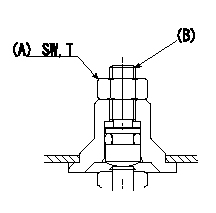
BCS adjustment procedure
1. At full boost pressure, set so that the full injection quantity is within the specifications (adjusting point).
2. Perform boost compensator intermediate operation point adjustment (pump speed N1, boost pressure P1).
3. When injection quantity at boost pressure P2 and pump speed N2 is not as specified, loosen nut (A) and adjust position of screw (B) so that injection quantity is as specified. The screw position should be within +-1 turn of initial position.
4. The nut tightening torque is T.
----------
N1=800r/min N2=500r/min P1=18.7kPa(140mmHg) P2=0kPa(0mmHg) T=6~9N-m(0.6~0.9kgf-m)
----------
SW=10mm T=6~9N-m(0.6~0.9kgf-m)
----------
N1=800r/min N2=500r/min P1=18.7kPa(140mmHg) P2=0kPa(0mmHg) T=6~9N-m(0.6~0.9kgf-m)
----------
SW=10mm T=6~9N-m(0.6~0.9kgf-m)
0000001801 W-CSD ADJUSTMENT
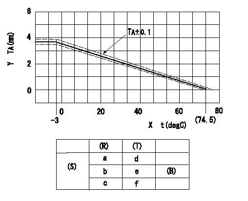
Adjustment of the W-CSD
Adjustment of the timer advance angle
1. Determine the timer advance angle using the graph (graph TA).
X:Temperature t (deg C)
Y:Timer stroke TA (mm)
(S) Cold advance
(R) Cooling water temperature (deg C)
(T) Timer piston stroke (mm)
(B) Standard point
----------
TA=-0.053t+3.881 -3<=t<=20 TA=-0.0517t+3.854 20<=t
----------
a=76.5++degC b=20degC c=-3degC d=0mm e=2.82+-0.4mm f=4.04+-0.6mm
----------
TA=-0.053t+3.881 -3<=t<=20 TA=-0.0517t+3.854 20<=t
----------
a=76.5++degC b=20degC c=-3degC d=0mm e=2.82+-0.4mm f=4.04+-0.6mm
0000001901 TAMPER PROOF
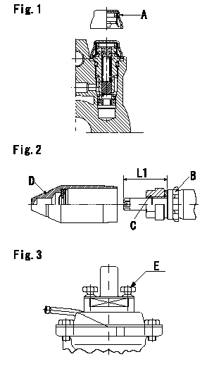
Tamperproof installation procedure
A:Cap
B:Rubber vibration damper
C:Nut
D:Cap
E:Position of break
L1:Inspection dimension
Fig. 1 Regulating valve seal
1) Insert the cap A horizontally (press fit).
2) After insertion (press-fitting), tighten the cap to torque T1, and confirm that it is not pulled out at load F1.
Fig.2 Full load adjusting screw
1) Confirm the position of the rubber vibration damper (B) and then tighten nut (C) to the torque T2.
Fig. 3 External-adjustment type cover governor seal
1) Target breaking torque T3
----------
L1=23~28mm F1=49N(5kgf) T1=4.9N-m(0.5kgf-m) T2=7~9N-m(0.7~0.9kgf-m) T3=2.94~4.41N-m(0.3~0.45kgf-m)
----------
L1=23~28mm
----------
L1=23~28mm F1=49N(5kgf) T1=4.9N-m(0.5kgf-m) T2=7~9N-m(0.7~0.9kgf-m) T3=2.94~4.41N-m(0.3~0.45kgf-m)
----------
L1=23~28mm
0000002001 STARTING I/Q ADJUSTMENT
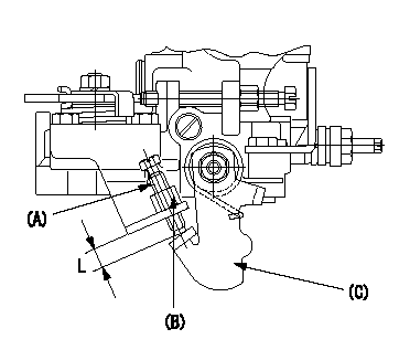
Starting Q decrease lever adjustment
Adjust using the screw (A) so that the standards are satisfied, then fix using the nut (B).
Screw (A) protrusion: L
(B) Nut (SW10, T1 after completing adjustment)
(C) Stop lever
----------
L=7.4~11.1mm T1=6~9N-m(0.6~0.9kgf-m)
----------
L=7.4~11.1mm
----------
L=7.4~11.1mm T1=6~9N-m(0.6~0.9kgf-m)
----------
L=7.4~11.1mm
Information:
Caterpillar's Scheduled Oil Sampling (S O S) is the best indicator for determining what is happening inside your engine.S O S is a diagnostic tool used to determine oil performance and component wear rates with a series of tests designed to identify and measure contamination such as soot, sulfur, etc. and degradation such as the presence of fuel, water and antifreeze in a sample of oil.The tests also determine the amount of wear metals present in the oil sample, which is compared to established Caterpillar norms to determine acceptability. To be effective as an indicator, S O S must be performed on a continuing basis. Intermittent sampling will not allow wear rate trend lines to be established.Obtain S O S samples at regularly scheduled intervals to monitor the condition and maintenance requirements of your engine. Each oil sample should be taken when the oil is warm and well mixed to ensure that the sample is representative of the oil in the engine crankcase and oil pan.Consult your Caterpillar dealer for complete information and assistance in establishing an S O S program for your engine(s). S O S AnalysisS O S is composed of three basic tests:* Wear Analysis* Chemical and Physical Tests* Oil Condition Analysis Wear Analysis is performed with an atomic absorption spectrophotometer to monitor component wear by identifying and measuring concentrations, in parts per million, of wear elements present in the oil. Based on known normal concentration data, maximum limits of wear elements are established. Impending failures can be identified when test results deviate from concentration levels established as acceptable, based on normal wear. Chemical and Physical Tests detect the presence of water, fuel and glycol (antifreeze) in the oil and determine whether or not their concentrations exceed established maximum limits. Oil Condition Analysis is evaluated with infrared analysis (IR). This test determines the presence and measures the amount of contaminants such as soot, sulfur products, oxidation, and nitration products in the oil. Infrared analysis can also assist in customizing (reducing, maintaining or extending) oil change intervals for particular conditions and applications.Infrared analysis should always be accompanied by wear element analysis and chemical and physical tests to assure accurate diagnosis. Infrared analysis must be used to determine oil change intervals. S O S must include Infrared (IR) in the analysis.The test results of the oil samples will then be used as a basis for determining the oil change interval for your engine, giving you the ultimate time between oil changes without the risk of engine damage.Refer to Caterpillar pamphlet Scheduled Oil Sampling, form PEDP7105 for information and benefits of S O S. Obtain SampleEach oil sample should be taken when the oil is warm and well mixed to ensure that the sample is representative of the oil in the crankcase.There are two methods recommended to obtain S O S samples from the 3176 engine crankcase. * Use the sampling valve, if installed on the engine, for samples.* Use a sampling gun inserted into the sump. Refer
Have questions with 104747-7110?
Group cross 104747-7110 ZEXEL
Komatsu
104747-7110
6273711140
INJECTION-PUMP ASSEMBLY
S4D95LWE-
S4D95LWE-