Information injection-pump assembly
BOSCH
F 01G 09W 0BW
f01g09w0bw
ZEXEL
104747-7101
1047477101
KOMATSU
6273711130
6273711130
Rating:
Components :
| 0. | INJECTION-PUMP ASSEMBLY | 104747-7101 |
| 1. | _ | |
| 2. | FUEL INJECTION PUMP | |
| 3. | NUMBER PLATE | |
| 4. | _ | |
| 5. | CAPSULE | |
| 6. | ADJUSTING DEVICE | |
| 7. | NOZZLE AND HOLDER ASSY | 105141-2520 |
| 8. | Nozzle and Holder | |
| 9. | Open Pre:MPa(Kqf/cm2) | 11.8(120) |
| 10. | NOZZLE-HOLDER | 105071-1450 |
| 11. | NOZZLE | 105000-1770 |
Scheme ###:
| 1/6. | [1] | 146601-1100 | PACKING RING |
| 6. | [1] | 146100-0220 | SUPPLY PUMP |
| 9. | [1] | 146103-0100 | COVER |
| 10. | [2] | 139104-0000 | FLAT-HEAD SCREW |
| 12. | [1] | 146200-0320 | DRIVE SHAFT |
| 12/1. | [1] | 146200-0300 | DRIVE SHAFT |
| 12/2. | [1] | 146201-0000 | WOODRUFF KEY |
| 12/3. | [2] | 146202-0100 | DAMPER |
| 12/4. | [1] | 146203-0000 | TOOTHED GEAR |
| 17. | [1] | 146204-0000 | PLAIN WASHER |
| 20. | [1] | 146210-3520 | ROLLER SET |
| 24. | [1] | 146303-0000 | BEARING PIN |
| 25. | [1] | 146304-0000 | BEARING PIN |
| 26. | [1] | 146305-0000 | CLAMPING BAND |
| 27. | [1] | 146205-0200 | SLOTTED WASHER |
| 29. | [1] | 146220-4820 | CAM PLATE |
| 30. | [1] | 146600-0800 | O-RING |
| 31. | [1] | 146311-5620 | PUMP PLUNGER |
| 32. | [1] | 146301-0000 | SLIDING PIECE |
| 34. | [1] | 146312-5600 | COMPRESSION SPRING |
| 35/1. | [1] | 146690-3200 | SHIM D11.5&9.4T0.1 |
| 35/1. | [1] | 146690-3300 | SHIM D11.5&9.4T0.2 |
| 35/1. | [1] | 146690-3400 | SHIM D11.5&9.4T0.25 |
| 35/1. | [1] | 146690-3500 | SHIM D11.5&9.4T1.0 |
| 35/1. | [1] | 146690-4100 | SHIM D11.5&9.4T2 |
| 35/1. | [1] | 146690-4200 | SHIM D11.5&9.4T0.5 |
| 35/1. | [1] | 146690-4300 | SHIM D11.5&9.4T0.75 |
| 36. | [1] | 146600-0800 | O-RING |
| 37. | [1] | 146310-4020 | COVER |
| 38. | [2] | 146620-5000 | BLEEDER SCREW |
| 39. | [1] | 146310-0100 | COVER |
| 40. | [2] | 146620-5000 | BLEEDER SCREW |
| 41. | [1] | 146312-1900 | COMPRESSION SPRING |
| 43. | [1] | 146230-0000 | SHIM |
| 44. | [1] | 146230-0100 | PLAIN WASHER |
| 45. | [1] | 146231-0001 | SLOTTED WASHER |
| 47. | [2] | 146233-0000 | SLOTTED WASHER |
| 48/1. | [1] | 146603-0000 | SHIM D17.0&5.2T0.50 |
| 48/1. | [1] | 146603-0100 | SHIM D17.0&5.2T0.80 |
| 48/1. | [1] | 146603-0200 | SHIM D17.0&5.2T1.00 |
| 48/1. | [1] | 146603-0300 | SHIM D17.0&5.2T1.20 |
| 48/1. | [1] | 146603-0400 | SHIM D17.0&5.2T1.50 |
| 48/1. | [1] | 146603-0500 | SHIM D17.0&5.2T1.80 |
| 48/1. | [1] | 146603-0600 | SHIM D17.0&5.2T2.00 |
| 48/1. | [1] | 146690-1400 | SHIM D17&5.2T0.9 |
| 48/1. | [1] | 146690-1500 | SHIM D17&5.2T1.1 |
| 48/1. | [1] | 146690-1600 | SHIM D17&5.2T1.3 |
| 48/1. | [1] | 146690-1700 | SHIM D17&5.2T1.4 |
| 48/1. | [1] | 146690-1800 | SHIM D17&5.2T1.6 |
| 48/1. | [1] | 146690-1900 | SHIM D17&5.2T1.7 |
| 48/1. | [1] | 146690-5800 | SHIM D17&5.2T2.1 |
| 48/1. | [1] | 146690-5900 | SHIM D17&5.2T2.2 |
| 48/1. | [1] | 146690-6000 | SHIM D17&5.2T2.3 |
| 48/1. | [1] | 146690-6100 | SHIM D17&5.2T2.4 |
| 48/1. | [1] | 146690-6200 | SHIM D17&5.2T2.5 |
| 48/1. | [1] | 146690-6300 | SHIM D17&5.2T2.6 |
| 48/1. | [1] | 146690-6400 | SHIM D17&5.2T2.7 |
| 48/1. | [1] | 146690-6500 | SHIM D17&5.2T2.8 |
| 48/1. | [1] | 146690-6600 | SHIM D17&5.2T2.9 |
| 48/1. | [1] | 146690-6700 | SHIM D17&5.2T3.0 |
| 48/1. | [1] | 146690-6800 | SHIM D17&5.2T3.1 |
| 48/1. | [1] | 146690-6900 | SHIM D17&5.2T3.2 |
| 48/1. | [1] | 146690-7000 | SHIM D17&5.2T3.3 |
| 48/1. | [1] | 146690-7100 | SHIM D17&5.2T3.4 |
| 48/1. | [1] | 146690-7200 | SHIM D17&5.2T0.4 |
| 48/1. | [1] | 146690-7300 | SHIM D17&5.2T0.6 |
| 48/1. | [1] | 146690-7400 | SHIM D17&5.2T0.7 |
| 48/1. | [1] | 146690-7500 | SHIM D17&5.2T1.9 |
| 48/1. | [1] | 146690-7800 | SHIM D17&5.2T0.2 |
| 49. | [2] | 146234-0600 | GUIDE PIN |
| 50. | [1] | 146403-9820 | HYDRAULIC HEAD |
| 50. | [1] | 146403-9820 | HYDRAULIC HEAD |
| 50. | [1] | 146403-9820 | HYDRAULIC HEAD |
| 51. | [1] | 146600-0000 | O-RING |
| 52/1. | [1] | 146420-0000 | SHIM D9.5&3.0T1.90 |
| 52/1. | [1] | 146420-0100 | SHIM D9.5&3.0T1.92 |
| 52/1. | [1] | 146420-0200 | SHIM D9.5&3.0T1.94 |
| 52/1. | [1] | 146420-0300 | SHIM D9.5&3.0T1.96 |
| 52/1. | [1] | 146420-0400 | SHIM D9.5&3.0T1.98 |
| 52/1. | [1] | 146420-0500 | SHIM D9.5&3.0T2.00 |
| 52/1. | [1] | 146420-0600 | SHIM D9.5&3.0T2.02 |
| 52/1. | [1] | 146420-0700 | SHIM D9.5&3.0T2.04 |
| 52/1. | [1] | 146420-0800 | SHIM D9.5&3.0T2.06 |
| 52/1. | [1] | 146420-0900 | SHIM D9.5&3.0T2.08 |
| 52/1. | [1] | 146420-1000 | SHIM D9.5&3.0T2.10 |
| 52/1. | [1] | 146420-1100 | SHIM D9.5&3.0T2.12 |
| 52/1. | [1] | 146420-1200 | SHIM D9.5&3.0T2.14 |
| 52/1. | [1] | 146420-1300 | SHIM D9.5&3.0T2.16 |
| 52/1. | [1] | 146420-1400 | SHIM D9.5&3.0T2.18 |
| 52/1. | [1] | 146420-1500 | SHIM D9.5&3.0T2.20 |
| 52/1. | [1] | 146420-1600 | SHIM D9.5&3.0T2.22 |
| 52/1. | [1] | 146420-1700 | SHIM D9.5&3.0T2.24 |
| 52/1. | [1] | 146420-1800 | SHIM D9.5&3.0T2.26 |
| 52/1. | [1] | 146420-1900 | SHIM D9.5&3.0T2.28 |
| 52/1. | [1] | 146420-2000 | SHIM D9.5&3.0T2.30 |
| 52/1. | [1] | 146420-2100 | SHIM D9.5&3.0T2.32 |
| 52/1. | [1] | 146420-2200 | SHIM D9.5&3.0T2.34 |
| 52/1. | [1] | 146420-2300 | SHIM D9.5&3.0T2.36 |
| 52/1. | [1] | 146420-2400 | SHIM D9.5&3.0T2.38 |
| 52/1. | [1] | 146420-2500 | SHIM D9.5&3.0T2.40 |
| 52/1. | [1] | 146420-2600 | SHIM D9.5&3.0T2.42 |
| 52/1. | [1] | 146420-2700 | SHIM D9.5&3.0T2.44 |
| 52/1. | [1] | 146420-2800 | SHIM D9.5&3.0T2.46 |
| 52/1. | [1] | 146420-2900 | SHIM D9.5&3.0T2.48 |
| 52/1. | [1] | 146420-3000 | SHIM D9.5&3.0T2.50 |
| 52/1. | [1] | 146420-3100 | SHIM D9.5&3.0T2.52 |
| 52/1. | [1] | 146420-3200 | SHIM D9.5&3.0T2.54 |
| 52/1. | [1] | 146420-3300 | SHIM D9.5&3.0T2.56 |
| 52/1. | [1] | 146420-3400 | SHIM D9.5&3.0T2.58 |
| 52/1. | [1] | 146420-3500 | SHIM D9.5&3.0T2.60 |
| 52/1. | [1] | 146420-3600 | SHIM D9.5&3.0T2.62 |
| 52/1. | [1] | 146420-3700 | SHIM D9.5&3.0T2.64 |
| 52/1. | [1] | 146420-3800 | SHIM D9.5&3.0T2.66 |
| 52/1. | [1] | 146420-3900 | SHIM D9.5&3.0T2.68 |
| 52/1. | [1] | 146420-4000 | SHIM D9.5&3.0T2.70 |
| 52/1. | [1] | 146420-4100 | SHIM D9.5&3.0T2.72 |
| 52/1. | [1] | 146420-4200 | SHIM D9.5&3.0T2.74 |
| 52/1. | [1] | 146420-4300 | SHIM D9.5&3.0T2.76 |
| 52/1. | [1] | 146420-4400 | SHIM D9.5&3.0T2.78 |
| 52/1. | [1] | 146420-4500 | SHIM D9.5&3.0T2.80 |
| 52/1. | [1] | 146420-4600 | SHIM D9.5&3.0T2.82 |
| 52/1. | [1] | 146420-4700 | SHIM D9.5&3.0T2.84 |
| 52/1. | [1] | 146420-4800 | SHIM D9.5&3.0T2.86 |
| 52/1. | [1] | 146420-4900 | SHIM D9.5&3.0T2.88 |
| 52/1. | [1] | 146420-5000 | SHIM D9.5&3.0T2.90 |
| 52/1. | [1] | 146420-5100 | SHIM D9.5&3.0T1.74 |
| 52/1. | [1] | 146420-5200 | SHIM D9.5&3.0T1.76 |
| 52/1. | [1] | 146420-5300 | SHIM D9.5&3.0T1.78 |
| 52/1. | [1] | 146420-5400 | SHIM D9.5&3.0T1.80 |
| 52/1. | [1] | 146420-5500 | SHIM D9.5&3.0T1.82 |
| 52/1. | [1] | 146420-5600 | SHIM D9.5&3.0T1.84 |
| 52/1. | [1] | 146420-5700 | SHIM D9.5&3.0T1.86 |
| 52/1. | [1] | 146420-5800 | SHIM D9.5&3.0T1.88 |
| 54. | [4] | 146433-0100 | GASKET |
| 55. | [4] | 146430-8220 | DELIVERY-VALVE ASSEMBLY VE82 |
| 56. | [4] | 146432-0000 | COMPRESSION SPRING |
| 58. | [4] | 146440-2720 | FITTING |
| 60. | [3] | 139106-0100 | FLAT-HEAD SCREW |
| 67. | [1] | 146822-3520 | GOVERNOR COVER |
| 67/1. | [1] | 146508-1022 | GOVERNOR COVER |
| 67/2. | [1] | 146515-0220 | CONTROL SHAFT |
| 67/3. | [1] | 146600-0100 | O-RING |
| 67/4. | [2] | 139310-0200 | PLAIN WASHER |
| 67/4. | [2] | 139310-0200 | PLAIN WASHER |
| 67/5. | [1] | 146530-0000 | CONTROL LEVER |
| 67/5B. | [1] | 146530-0100 | CONTROL LEVER STAMP 001 |
| 67/5C. | [1] | 146832-1500 | CONTROL LEVER |
| 67/5D. | [1] | 146832-1600 | CONTROL LEVER |
| 67/6. | [2] | 014110-6440 | LOCKING WASHER D12.2&6.1T1.5 |
| 67/6. | [2] | 014110-6440 | LOCKING WASHER D12.2&6.1T1.5 |
| 67/7. | [1] | 013020-6040 | UNION NUT |
| 67/8. | [1] | 146515-1820 | LEVER SHAFT |
| 67/9. | [1] | 146587-4500 | COILED SPRING |
| 67/10. | [1] | 146600-0200 | O-RING |
| 67/11. | [1] | 146602-0100 | PLAIN WASHER |
| 67/12. | [1] | 146540-5600 | CONTROL LEVER |
| 67/12B. | [1] | 146540-5700 | CONTROL LEVER |
| 67/12C. | [1] | 146540-5800 | CONTROL LEVER |
| 67/12D. | [1] | 146540-5900 | CONTROL LEVER |
| 67/13. | [1] | 146621-1700 | UNION NUT |
| 67/14. | [1] | 146621-1700 | UNION NUT |
| 67/15. | [1] | 146526-2800 | BLEEDER SCREW |
| 67/16. | [1] | 146526-2800 | BLEEDER SCREW |
| 67/18. | [1] | 146587-2000 | COILED SPRING |
| 67/19. | [1] | 146541-0000 | ANGLE PIECE |
| 67/23. | [1] | 146936-6520 | BRACKET |
| 67/24. | [2] | 139006-4500 | BLEEDER SCREW |
| 67/25. | [1] | 013020-6040 | UNION NUT |
| 67/78. | [1] | 146600-4400 | SEAL RING |
| 67/200. | [1] | 139308-0300 | PLAIN WASHER |
| 67/201. | [1] | 146545-4600 | THREADED PIN L=24MM |
| 67/201B. | [1] | 146545-4700 | THREADED PIN L=26MM |
| 67/201C. | [1] | 146545-4800 | THREADED PIN L=28MM |
| 67/201D. | [1] | 146545-5000 | THREADED PIN |
| 67/202. | [1] | 146598-5000 | UNION NUT |
| 67/203. | [1] | 146600-1200 | O-RING |
| 67/204. | [1] | 146545-4500 | DAMPER |
| 95. | [1] | 146891-3420 | FULCRUM LEVER |
| 104. | [2] | 146568-0000 | SLOTTED SPRING PIN |
| 105. | [2] | 026508-1140 | GASKET D11.4&8.2T1.0 |
| 106. | [2] | 146588-0500 | COILED SPRING |
| 107. | [1] | 146569-0300 | UNION NUT |
| 108. | [1] | 146570-0420 | GOVERNOR SHAFT |
| 109. | [1] | 146600-0400 | O-RING |
| 110/1. | [1] | 146571-0000 | SHIM D20.2&8.3T1.05 |
| 110/1. | [1] | 146571-0100 | SHIM D20.2&8.3T1.25 |
| 110/1. | [1] | 146571-0200 | SHIM D20.2&8.3T1.45 |
| 110/1. | [1] | 146571-0300 | SHIM D20.2&8.3T1.65 |
| 110/1. | [1] | 146571-0400 | SHIM D20.2&8.3T1.85 |
| 110/1. | [1] | 146571-0500 | SHIM D20.2&8.3T1.15 |
| 110/1. | [1] | 146571-0600 | SHIM D20.2&8.3T1.35 |
| 110/1. | [1] | 146571-0700 | SHIM D20.2&8.3T1.55 |
| 110/1. | [1] | 146571-0800 | SHIM D20.2&8.3T1.75 |
| 111. | [1] | 146602-0600 | PLAIN WASHER |
| 112. | [1] | 146572-0020 | FLYWEIGHT ASSEMBLY |
| 114. | [1] | 146602-2600 | PLAIN WASHER |
| 115. | [1] | 146976-3500 | SLIDING SLEEVE |
| 116. | [1] | 146576-0400 | CAP |
| 117/1. | [1] | 146877-0820 | PLUG L=5.0 |
| 117/1. | [1] | 146877-0920 | PLUG L=5.1 |
| 117/1. | [1] | 146877-1020 | PLUG L=5.2 |
| 117/1. | [1] | 146877-1120 | PLUG L=5.3 |
| 117/1. | [1] | 146877-1220 | PLUG L=5.4 |
| 117/1. | [1] | 146877-1320 | PLUG L=5.5 |
| 117/1. | [1] | 146877-1420 | PLUG L=5.6 |
| 117/1. | [1] | 146877-1520 | PLUG L=5.7 |
| 117/1. | [1] | 146877-1620 | PLUG L=5.8 |
| 117/1. | [1] | 146877-1720 | PLUG L=5.9 |
| 117/1. | [1] | 146877-1820 | PLUG L=6.0 |
| 117/1. | [1] | 146877-1920 | PLUG L=6.1 |
| 117/1. | [1] | 146877-2020 | PLUG L=6.2 |
| 117/1. | [1] | 146877-2120 | PLUG L=6.3 |
| 117/1. | [1] | 146877-2220 | PLUG L=6.4 |
| 117/1. | [1] | 146877-2320 | PLUG L=6.5 |
| 117/1. | [1] | 146877-2420 | PLUG L=6.6 |
| 117/1. | [1] | 146877-2520 | PLUG L=6.7 |
| 117/1. | [1] | 146877-2620 | PLUG L=6.8 |
| 117/1. | [1] | 146877-2720 | PLUG L=6.9 |
| 117/1. | [1] | 146877-2820 | PLUG L=7.0 |
| 117/1. | [1] | 146877-2920 | PLUG L=7.1 |
| 117/1. | [1] | 146877-3020 | PLUG L=7.2 |
| 117/1. | [1] | 146877-3120 | PLUG L=7.3 |
| 117/1. | [1] | 146877-3220 | PLUG L=7.4 |
| 117/1. | [1] | 146877-3320 | PLUG L=7.5 |
| 117/1. | [1] | 146877-3420 | PLUG L=7.6 |
| 117/1. | [1] | 146877-3520 | PLUG L=7.7 |
| 117/1. | [1] | 146877-3620 | PLUG L=7.8 |
| 117/1. | [1] | 146877-3720 | PLUG L=7.9 |
| 117/1. | [1] | 146877-3820 | PLUG L=8.0 |
| 117/1. | [1] | 146877-3920 | PLUG L=8.1 |
| 117/1. | [1] | 146877-4020 | PLUG L=8.2 |
| 117/1. | [1] | 146877-4120 | PLUG L=8.3 |
| 117/1. | [1] | 146877-4220 | PLUG L=8.4 |
| 120. | [1] | 146879-3120 | RETAINING PIN |
| 122. | [1] | 146580-2800 | GOVERNOR SPRING |
| 123. | [4] | 139106-0200 | FLAT-HEAD SCREW |
| 130. | [1] | 146421-0020 | CAPSULE |
| 130/2. | [1] | 026508-1140 | GASKET D11.4&8.2T1.0 |
| 130/3. | [1] | 146422-0000 | BLEEDER SCREW |
| 130/4. | [1] | 146600-0500 | O-RING |
| 133. | [1] | 146600-0600 | O-RING |
| 134. | [1] | 146600-0700 | O-RING |
| 135. | [1] | 146110-0920 | CONTROL VALVE |
| 135/5. | [1] | 146114-0000 | SPRING WASHER |
| 136. | [1] | 146120-0120 | OVER FLOW VALVE |
| 137. | [2] | 139512-0500 | GASKET |
| 200. | [1] | 146206-0100 | COILED SPRING |
| 205. | [1] | 029470-4030 | WOODRUFF KEY |
| 232. | [1] | 146931-3200 | BRACKET STAMP 132 |
| 234. | [1] | 139006-4800 | BLEEDER SCREW |
| 237. | [1] | 146620-0200 | HEX-SOCKET-HEAD CAP SCREW |
| 240. | [1] | 146650-1220 | PULLING ELECTROMAGNET |
| 240/8. | [1] | 146600-1700 | O-RING |
| 242. | [1] | 146662-1420 | WIRE |
| 243. | [1] | 146621-4901 | UNION NUT |
| 245. | [3] | 139512-0500 | GASKET |
| 246. | [1] | 146125-0700 | EYE BOLT |
| 248. | [1] | 146614-0200 | SPACER BUSHING |
| 251. | [1] | 146125-0101 | FILTER |
| 252. | [1] | 146125-0200 | COILED SPRING |
| 280. | [1] | 146361-6620 | START ADVANCE ASSY |
| 281. | [1] | 146600-0800 | O-RING |
| 282. | [2] | 010206-1240 | HEX-SOCKET-HEAD CAP SCREW |
| 286. | [1] | 020106-3040 | BLEEDER SCREW |
| 287. | [1] | 014010-6140 | PLAIN WASHER D13&6.5T1.0 |
| 343. | [1] | 146598-8320 | CAP |
| 800S. | [1] | 146020-3220 | PUMP HOUSING |
| 800S/1/6. | [1] | 146601-1100 | PACKING RING |
| 804S. | [1] | 146232-0720 | COMPRESSION SPRING |
| 805S. | [1] | 146574-0320 | PARTS SET |
| 810S. | [1] | 146600-1120 | REPAIR SET |
| 821S. | [1] | 146210-5720 | ROLLER SET |
| 825S. | [1] | 146598-8120 | CAP |
| 835S. | [1] | 146598-7320 | CAP |
| 836S/1. | [1] | 146598-0600 | CAP L18 |
| 836S/1. | [1] | 146598-0700 | CAP L21 |
| 836S/1. | [1] | 146598-0800 | CAP L24 |
| 836S/1. | [1] | 146598-0900 | CAP L27 |
| 837S. | [1] | 146598-7310 | CAP |
| 906. | [1] | 146985-2800 | NAMEPLATE |
Include in #2:
104747-7101
as INJECTION-PUMP ASSEMBLY
Cross reference number
BOSCH
F 01G 09W 0BW
f01g09w0bw
ZEXEL
104747-7101
1047477101
KOMATSU
6273711130
6273711130
Zexel num
Bosch num
Firm num
Name
104747-7101
F 01G 09W 0BW
6273711130 KOMATSU
INJECTION-PUMP ASSEMBLY
S4D95LWE-
S4D95LWE-
Calibration Data:
Adjustment conditions
Test oil
1404 Test oil ISO4113orSAEJ967d
1404 Test oil ISO4113orSAEJ967d
Test oil temperature
degC
45
45
50
Nozzle
105780-0060
Bosch type code
NP-DN0SD1510
Nozzle holder
105780-2150
Opening pressure
MPa
13
13
13.3
Opening pressure
kgf/cm2
133
133
136
Injection pipe
157805-7320
Injection pipe
Inside diameter - outside diameter - length (mm) mm 2-6-450
Inside diameter - outside diameter - length (mm) mm 2-6-450
Joint assembly
157641-4720
Tube assembly
157641-4020
Transfer pump pressure
kPa
20
20
20
Transfer pump pressure
kgf/cm2
0.2
0.2
0.2
Direction of rotation (viewed from drive side)
Right R
Right R
Injection timing adjustment
Pump speed
r/min
800
800
800
Average injection quantity
mm3/st.
65.3
64.8
65.8
Difference in delivery
mm3/st.
5
Basic
*
Oil temperature
degC
50
48
52
Injection timing adjustment_02
Pump speed
r/min
450
450
450
Average injection quantity
mm3/st.
52.1
48.1
56.1
Oil temperature
degC
48
46
50
Injection timing adjustment_03
Pump speed
r/min
800
800
800
Average injection quantity
mm3/st.
65.3
64.3
66.3
Difference in delivery
mm3/st.
5.5
Basic
*
Oil temperature
degC
50
48
52
Injection timing adjustment_04
Pump speed
r/min
900
900
900
Average injection quantity
mm3/st.
63.3
59.8
66.8
Oil temperature
degC
50
48
52
Injection timing adjustment_05
Pump speed
r/min
1135
1135
1135
Average injection quantity
mm3/st.
57.1
53.1
61.1
Oil temperature
degC
50
48
52
Injection quantity adjustment
Pump speed
r/min
1260
1260
1260
Average injection quantity
mm3/st.
12.1
9.1
15.1
Difference in delivery
mm3/st.
3.5
Basic
*
Oil temperature
degC
50
48
52
Injection quantity adjustment_02
Pump speed
r/min
1425
1425
1425
Average injection quantity
mm3/st.
3
Oil temperature
degC
50
48
52
Injection quantity adjustment_03
Pump speed
r/min
1260
1260
1260
Average injection quantity
mm3/st.
12.1
7.6
16.6
Basic
*
Oil temperature
degC
50
48
52
Governor adjustment
Pump speed
r/min
450
450
450
Average injection quantity
mm3/st.
9.9
7.9
11.9
Difference in delivery
mm3/st.
2
Basic
*
Oil temperature
degC
48
46
50
Governor adjustment_02
Pump speed
r/min
450
450
450
Average injection quantity
mm3/st.
9.9
7.4
12.4
Difference in delivery
mm3/st.
2.5
Basic
*
Oil temperature
degC
48
46
50
Timer adjustment
Pump speed
r/min
100
100
100
Average injection quantity
mm3/st.
80
75
85
Basic
*
Oil temperature
degC
48
46
50
Remarks
IDLE
IDLE
Timer adjustment_02
Pump speed
r/min
100
100
100
Average injection quantity
mm3/st.
80
75
85
Oil temperature
degC
48
46
50
Remarks
IDLE
IDLE
Speed control lever angle
Pump speed
r/min
450
450
450
Average injection quantity
mm3/st.
0
0
0
Oil temperature
degC
48
46
50
Remarks
Magnet OFF at idling position
Magnet OFF at idling position
0000000901
Pump speed
r/min
1135
1135
1135
Overflow quantity
cm3/min
410
280
540
Oil temperature
degC
50
48
52
Stop lever angle
Pump speed
r/min
1135
1135
1135
Pressure
kPa
510
490
530
Pressure
kgf/cm2
5.2
5
5.4
Basic
*
Oil temperature
degC
50
48
52
Stop lever angle_02
Pump speed
r/min
900
900
900
Pressure
kPa
441
392
490
Pressure
kgf/cm2
4.5
4
5
Oil temperature
degC
50
48
52
Stop lever angle_03
Pump speed
r/min
1100
1100
1100
Pressure
kPa
500
451
549
Pressure
kgf/cm2
5.1
4.6
5.6
Oil temperature
degC
50
48
52
Stop lever angle_04
Pump speed
r/min
1135
1135
1135
Pressure
kPa
510
481
539
Pressure
kgf/cm2
5.2
4.9
5.5
Basic
*
Oil temperature
degC
50
48
52
0000001101
Pump speed
r/min
1135
1135
1135
Timer stroke
mm
1.8
1.6
2
Basic
*
Oil temperature
degC
50
48
52
_02
Pump speed
r/min
900
900
900
Timer stroke
mm
0.5
0
1
Oil temperature
degC
50
48
52
_03
Pump speed
r/min
1135
1135
1135
Timer stroke
mm
1.8
1.5
2.1
Basic
*
Oil temperature
degC
50
48
52
0000001201
Max. applied voltage
V
8
8
8
Test voltage
V
13
12
14
0000001401
Pump speed
r/min
1135
1135
1135
Average injection quantity
mm3/st.
47.5
46.5
48.5
Timer stroke TA
mm
1.3
1.1
1.5
Timer stroke variation dT
mm
0.5
0.5
0.5
Basic
*
Oil temperature
degC
50
48
52
_02
Pump speed
r/min
1135
1135
1135
Average injection quantity
mm3/st.
47.5
46
49
Timer stroke TA
mm
1.3
1
1.6
Timer stroke variation dT
mm
0.5
0.5
0.5
Basic
*
Oil temperature
degC
50
48
52
_03
Pump speed
r/min
1135
1135
1135
Average injection quantity
mm3/st.
38
36
40
Timer stroke TA
mm
0.8
0.3
1.3
Timer stroke variation dT
mm
1
1
1
Oil temperature
degC
50
48
52
Timing setting
K dimension
mm
3.3
3.2
3.4
KF dimension
mm
5.8
5.7
5.9
MS dimension
mm
2
1.9
2.1
Control lever angle alpha
deg.
16
12
20
Control lever angle beta
deg.
29
24
34
Test data Ex:
0000001801 W-CSD ADJUSTMENT
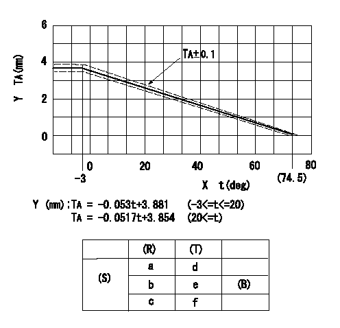
Adjustment of the W-CSD
X:Temperature t (deg C)
Y:Timer stroke TA (mm)
(S) Cold advance
(R) Cooling water temperature (deg C)
(T) Timer piston stroke (mm)
(B) Standard point
----------
----------
a=76.5++degC b=20degC c=-3degC d=0mm e=2.82+-0.4mm f=4.04+-0.6mm
----------
----------
a=76.5++degC b=20degC c=-3degC d=0mm e=2.82+-0.4mm f=4.04+-0.6mm
0000001901 STARTING I/Q ADJUSTMENT
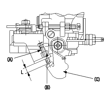
Starting Q decrease lever adjustment
Adjust using the screw (A) so that the standards are satisfied, then fix using the nut (B).
(B) Nut (SW10, T1 after completing adjustment)
(C) Stop lever
----------
T1=6~9N-m(0.6~0.9kgf-m)
----------
L=7.4~11.1mm
----------
T1=6~9N-m(0.6~0.9kgf-m)
----------
L=7.4~11.1mm
0000002001 TAMPER PROOF
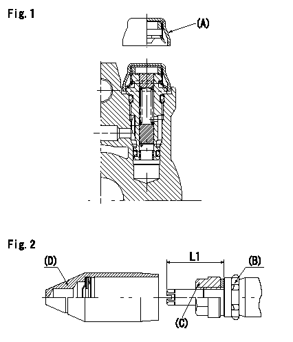
Tamperproof installation procedure
A:Cap
B:Rubber vibration damper
C:Nut
D:Cap
L1:Inspection dimension
Fig. 1 Regulating valve seal
1) Insert the cap A horizontally (press fit).
2) After insertion (press-fitting), tighten the cap to torque T1, and confirm that it is not pulled out at load F1.
Fig.2 Full load adjusting screw
1) Confirm the position of the rubber vibration damper (B) and then tighten nut (C) to the torque T2.
----------
L1=23~28mm F1=49N(5kgf) T1=4.9N-m(0.5kgf-m) T2=7~9N-m(0.7~0.9kgf-m)
----------
L1=23~28mm
----------
L1=23~28mm F1=49N(5kgf) T1=4.9N-m(0.5kgf-m) T2=7~9N-m(0.7~0.9kgf-m)
----------
L1=23~28mm
Information:
Adjustment of the fuel system outside Caterpillar specified limits will not improve fuel efficiency and could result in damage to the engine.
If you feel you have a vehicle performance problem, first consider the impact of vehicle efficiency and operating characteristics (vehicle speed, design, etc.), on power demand before questioning engine performance.In the case of poor fuel economy, the engine is not likely to be the cause without the presence of excessive exhaust smoke and/or a significant loss of power.If you feel you have a valid engine performance problem, contact an authorized Caterpillar dealer for assistance. If your engine is under warranty, then the Caterpillar warranty or extended service coverage (if purchased) will cover the cost of resolving a valid engine performance deficiency. Refer to the Warranty Section in this publication and your Caterpillar dealer for details.However, if the engine is not found at fault, all costs incurred will be the responsibility of the owner.Performance Analysis Report (PAR)
PAR complements a good preventive maintenance program. PAR analysis can monitor the condition of your engine and to determine if your engine is operating at peak efficiency.PAR reflects the results of various tests normally conducted by your Caterpillar dealer for the purpose of:* confirming your engine is operating efficiently and within specification.* identifying potential problems.* determining components or systems that should be adjusted, replaced, etc.Approximately eighty to 85% of your truck engine's total operation and maintenance cost is the cost of fuel. Therefore, substantial cost reductions can be achieved by keeping your engine operating at peak efficiency. Fuel consumption and performance of your engine is affected by vehicle specifications, how it is operated and condition of the engine. Each plays an important part in minimizing your total owner and operating cost.Do not attempt to use PAR until the first engine oil change. This allows for sufficient break-in of the engine, drive train and tires. Fuel rate and turbocharger boost will be measured under load at five engine speeds and compared to factory specifications. Fuel rate and boost are the primary indicators of your engine's performance and the analysis of this data will help pinpoint potential problems faster.Wheel horsepower (kW) will also be recorded during the initial PAR test to establish your truck's exact wheel horsepower (kW) over its full operating range. This power can then be compared to the power of subsequent PAR tests. Power available at the wheels is not only the result of the condition of the engine, but also the transmission, drive axle(s), brakes, tires and engine drive accessories.Consult your Caterpillar dealer for complete information and assistance in establishing a PAR program for your engine.Refer to Form LEDT4211, PEDP0026 and/or Performance Troubleshooting Manual, Form SENR4249 or your Caterpillar dealer for more information on PAR.Contact your nearest Caterpillar dealer for information on PAR and the location of the nearest, approved dynamometer.
Have questions with 104747-7101?
Group cross 104747-7101 ZEXEL
Komatsu
104747-7101
F 01G 09W 0BW
6273711130
INJECTION-PUMP ASSEMBLY
S4D95LWE-
S4D95LWE-