Information injection-pump assembly
ZEXEL
104747-7090
1047477090
KOMATSU
6273711220
6273711220
Rating:
Cross reference number
ZEXEL
104747-7090
1047477090
KOMATSU
6273711220
6273711220
Zexel num
Bosch num
Firm num
Name
104747-7090
6273711220 KOMATSU
INJECTION-PUMP ASSEMBLY
P162/CUMM
P162/CUMM
Calibration Data:
Adjustment conditions
Test oil
1404 Test oil ISO4113orSAEJ967d
1404 Test oil ISO4113orSAEJ967d
Test oil temperature
degC
45
45
50
Nozzle
105780-0060
Bosch type code
NP-DN0SD1510
Nozzle holder
105780-2150
Opening pressure
MPa
13
13
13.3
Opening pressure
kgf/cm2
133
133
136
Injection pipe
157805-7320
Injection pipe
Inside diameter - outside diameter - length (mm) mm 2-6-450
Inside diameter - outside diameter - length (mm) mm 2-6-450
Joint assembly
157641-4720
Tube assembly
157641-4020
Transfer pump pressure
kPa
20
20
20
Transfer pump pressure
kgf/cm2
0.2
0.2
0.2
Direction of rotation (viewed from drive side)
Right R
Right R
Injection timing adjustment
Pump speed
r/min
900
900
900
Average injection quantity
mm3/st.
67.2
66.7
67.7
Difference in delivery
mm3/st.
5
Basic
*
Oil temperature
degC
50
48
52
Injection timing adjustment_02
Pump speed
r/min
500
500
500
Average injection quantity
mm3/st.
57.8
53.3
62.3
Oil temperature
degC
48
46
50
Injection timing adjustment_03
Pump speed
r/min
800
800
800
Average injection quantity
mm3/st.
68.3
64.3
72.3
Oil temperature
degC
50
48
52
Injection timing adjustment_04
Pump speed
r/min
900
900
900
Average injection quantity
mm3/st.
67.2
65.7
68.7
Difference in delivery
mm3/st.
5.5
Basic
*
Oil temperature
degC
50
48
52
Injection timing adjustment_05
Pump speed
r/min
1050
1050
1050
Average injection quantity
mm3/st.
62.4
58.4
66.4
Oil temperature
degC
50
48
52
Injection quantity adjustment
Pump speed
r/min
1175
1175
1175
Average injection quantity
mm3/st.
33.8
30.8
36.8
Difference in delivery
mm3/st.
7
Basic
*
Oil temperature
degC
50
48
52
Injection quantity adjustment_02
Pump speed
r/min
1375
1375
1375
Average injection quantity
mm3/st.
3
Oil temperature
degC
50
48
52
Injection quantity adjustment_03
Pump speed
r/min
1175
1175
1175
Average injection quantity
mm3/st.
33.8
29.3
38.3
Basic
*
Oil temperature
degC
50
48
52
Governor adjustment
Pump speed
r/min
400
400
400
Average injection quantity
mm3/st.
8.6
6.6
10.6
Difference in delivery
mm3/st.
2
Basic
*
Oil temperature
degC
48
46
50
Governor adjustment_02
Pump speed
r/min
400
400
400
Average injection quantity
mm3/st.
8.6
6.1
11.1
Difference in delivery
mm3/st.
2.5
Basic
*
Oil temperature
degC
48
46
50
Timer adjustment
Pump speed
r/min
100
100
100
Average injection quantity
mm3/st.
80
75
85
Basic
*
Oil temperature
degC
48
46
50
Remarks
IDLE
IDLE
Timer adjustment_02
Pump speed
r/min
100
100
100
Average injection quantity
mm3/st.
80
75
85
Oil temperature
degC
48
46
50
Remarks
IDLE
IDLE
Speed control lever angle
Pump speed
r/min
400
400
400
Average injection quantity
mm3/st.
0
0
0
Oil temperature
degC
48
46
50
Remarks
Magnet OFF at idling position
Magnet OFF at idling position
0000000901
Pump speed
r/min
1050
1050
1050
Overflow quantity
cm3/min
410
280
540
Oil temperature
degC
50
48
52
Stop lever angle
Pump speed
r/min
1050
1050
1050
Pressure
kPa
510
490
530
Pressure
kgf/cm2
5.2
5
5.4
Basic
*
Oil temperature
degC
50
48
52
Stop lever angle_02
Pump speed
r/min
900
900
900
Pressure
kPa
451
402
500
Pressure
kgf/cm2
4.6
4.1
5.1
Oil temperature
degC
50
48
52
Stop lever angle_03
Pump speed
r/min
1000
1000
1000
Pressure
kPa
490
441
539
Pressure
kgf/cm2
5
4.5
5.5
Oil temperature
degC
50
48
52
Stop lever angle_04
Pump speed
r/min
1050
1050
1050
Pressure
kPa
510
481
539
Pressure
kgf/cm2
5.2
4.9
5.5
Basic
*
Oil temperature
degC
50
48
52
0000001101
Pump speed
r/min
1050
1050
1050
Timer stroke
mm
1.6
1.4
1.8
Basic
*
Oil temperature
degC
50
48
52
_02
Pump speed
r/min
900
900
900
Timer stroke
mm
0.4
0
0.9
Oil temperature
degC
50
48
52
_03
Pump speed
r/min
1050
1050
1050
Timer stroke
mm
1.6
1.3
1.9
Basic
*
Oil temperature
degC
50
48
52
0000001201
Max. applied voltage
V
16
16
16
Test voltage
V
25
24
26
0000001401
Pump speed
r/min
1050
1050
1050
Average injection quantity
mm3/st.
50
49
51
Timer stroke TA
mm
1
0.8
1.2
Timer stroke variation dT
mm
0.6
0.6
0.6
Basic
*
Oil temperature
degC
50
48
52
_02
Pump speed
r/min
1050
1050
1050
Average injection quantity
mm3/st.
50
48.5
51.5
Timer stroke TA
mm
1
0.7
1.3
Timer stroke variation dT
mm
0.6
0.6
0.6
Basic
*
Oil temperature
degC
50
48
52
_03
Pump speed
r/min
1050
1050
1050
Average injection quantity
mm3/st.
40
38
42
Timer stroke TA
mm
0.4
0
0.9
Timer stroke variation dT
mm
1.2
1.2
1.2
Oil temperature
degC
50
48
52
Timing setting
K dimension
mm
3.3
3.2
3.4
KF dimension
mm
5.8
5.7
5.9
MS dimension
mm
2
1.9
2.1
Control lever angle alpha
deg.
16
12
20
Control lever angle beta
deg.
33
28
38
Test data Ex:
0000001801 W-CSD ADJUSTMENT
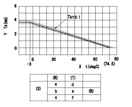
Adjustment of the W-CSD
Adjustment of the timer advance angle
1. Determine the timer advance angle using the graph (graph TA).
X:Temperature t (deg C)
Y:Timer stroke TA (mm)
(S) Cold advance
(R) Cooling water temperature (deg C)
(T) Timer piston stroke (mm)
(B) Standard point
----------
TA=-0.053t+3.881 -3degC<=t<=20degC TA=-0.0517t+3.854 20degC<=t
----------
a=76.5++degC b=20degC c=-3degC d=0mm e=2.82+-0.4mm f=4.04+-0.6mm
----------
TA=-0.053t+3.881 -3degC<=t<=20degC TA=-0.0517t+3.854 20degC<=t
----------
a=76.5++degC b=20degC c=-3degC d=0mm e=2.82+-0.4mm f=4.04+-0.6mm
0000001901 STARTING I/Q ADJUSTMENT
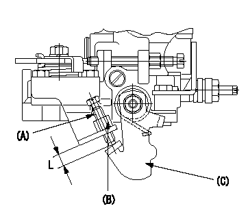
Starting Q decrease lever adjustment
Adjust using the screw (A) so that the standards are satisfied, then fix using the nut (B).
Screw (A) protrusion: L
(B) Nut (SW10, T1 after completing adjustment)
(C) Stop lever
----------
L=7.4~11.1mm T1=6~9N-m(0.6~0.9kgf-m)
----------
L=7.4~11.1mm
----------
L=7.4~11.1mm T1=6~9N-m(0.6~0.9kgf-m)
----------
L=7.4~11.1mm
0000002001 TAMPER PROOF
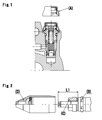
Tamperproof installation procedure
A:Cap
B:Rubber vibration damper
C:Nut
D:Cap
L1:Inspection dimension
Fig. 1 Regulating valve seal
1) Insert the cap A horizontally (press fit).
2) After insertion (press-fitting), tighten the cap to torque T1, and confirm that it is not pulled out at load F1.
Fig.2 Full load adjusting screw
1) Confirm the position of the rubber vibration damper (B) and then tighten nut (C) to the torque T2.
----------
L1=23~28mm F1=49N(5kgf) T1=4.9N-m(0.5kgf-m) T2=7~9N-m(0.7~0.9kgf-m)
----------
L1=23~28mm
----------
L1=23~28mm F1=49N(5kgf) T1=4.9N-m(0.5kgf-m) T2=7~9N-m(0.7~0.9kgf-m)
----------
L1=23~28mm
Information:
Caterpillar Diesel Truck Engines can operate effectively in cold weather, however, engine operation in cold weather is dependent on the type of fuel used and how well the fuel moves through fuel related components. The purpose of this section is to explain some of the problems and steps that can be taken to minimize fuel problems during cold weather operation when the engine area is colder than 40°F (5°C).Fuel and the Effect from Cold Weather
The two types of diesel fuel available for your truck engine are typically grades No. 1 and No. 2. Although No. 2 diesel fuel is the most commonly used fuel, No. 1 diesel fuel or a blend of No. 1 and No. 2, is the fuel that is best suited for cold weather operation.During cold weather operation, it may be necessary for you to use No. 2 diesel fuel since quantities of No. 1 diesel fuel are limited and generally are only available during the winter months and in the colder climates.There are three major differences between No. 1 and No. 2 diesel fuel. No. 1 diesel fuel has a lower cloud point, a lower pour point and has a lower BTU (kJ) (heat content) rating per unit volume of fuel than the average No. 2 diesel fuel.When using No. 1 diesel fuel, you may notice a drop in power and fuel efficiency, but should not experience any other operating effects.The cloud point is the temperature at which a cloud or haze of wax crystals will begin to form in the fuel and cause fuel filters to plug. The pour point is the temperature which diesel fuel will begin to thicken and be more resistant to flow through fuel pumps and lines.Be aware of these fuel values when purchasing your diesel fuel and anticipate the average outside (ambient) temperature for the area your engine will be operating. Engines fueled in one climate may not operate satisfactorily if moved to another because of problems that result from cold weather.Before troubleshooting for low power or poor performance in winter months, check the type of fuel being used.The use of starting aids, engine oil pan heaters, engine coolant heaters, fuel heaters and fuel line insulation also provide a means of minimizing starting and fuel problems in cold weather when No. 2 diesel fuel is used.Fuel Related Components in Cold Weather
The 3176 electronic control module is fuel cooled. Fuel is routed from the tank, to a primary fuel filter, through the transfer pump, then through cored passages in the electronic control module housing, on to the secondary fuel filter, and finally to the injection pump.Inlet fuel temperature to the transfer pump must never exceed 149°F (65°C). Fuel temperatures in excess of this temperature reduce the life of the electronics, reduce the life of the transfer pump check valves, and reduce engine power availability.Fuel Tanks
Fuel tanks should contain some provision for draining water and sediment from the bottom of the tanks.Some fuel tanks use supply pipes that allow water
Have questions with 104747-7090?
Group cross 104747-7090 ZEXEL
Komatsu
104747-7090
6273711220
INJECTION-PUMP ASSEMBLY
P162/CUMM
P162/CUMM