Information injection-pump assembly
ZEXEL
104747-7080
1047477080
KOMATSU
6273711120
6273711120
Rating:
Cross reference number
ZEXEL
104747-7080
1047477080
KOMATSU
6273711120
6273711120
Zexel num
Bosch num
Firm num
Name
104747-7080
6273711120 KOMATSU
INJECTION-PUMP ASSEMBLY
P162/CUMM
P162/CUMM
Calibration Data:
Adjustment conditions
Test oil
1404 Test oil ISO4113orSAEJ967d
1404 Test oil ISO4113orSAEJ967d
Test oil temperature
degC
45
45
50
Nozzle
105780-0060
Bosch type code
NP-DN0SD1510
Nozzle holder
105780-2150
Opening pressure
MPa
13
13
13.3
Opening pressure
kgf/cm2
133
133
136
Injection pipe
157805-7320
Injection pipe
Inside diameter - outside diameter - length (mm) mm 2-6-450
Inside diameter - outside diameter - length (mm) mm 2-6-450
Joint assembly
157641-4720
Tube assembly
157641-4020
Transfer pump pressure
kPa
20
20
20
Transfer pump pressure
kgf/cm2
0.2
0.2
0.2
Direction of rotation (viewed from drive side)
Right R
Right R
Injection timing adjustment
Pump speed
r/min
900
900
900
Average injection quantity
mm3/st.
67.2
66.7
67.7
Difference in delivery
mm3/st.
5
Basic
*
Oil temperature
degC
50
48
52
Injection timing adjustment_02
Pump speed
r/min
500
500
500
Average injection quantity
mm3/st.
57.8
53.3
62.3
Oil temperature
degC
48
46
50
Injection timing adjustment_03
Pump speed
r/min
800
800
800
Average injection quantity
mm3/st.
68.3
64.3
72.3
Oil temperature
degC
50
48
52
Injection timing adjustment_04
Pump speed
r/min
900
900
900
Average injection quantity
mm3/st.
67.2
65.7
68.7
Difference in delivery
mm3/st.
5.5
Basic
*
Oil temperature
degC
50
48
52
Injection timing adjustment_05
Pump speed
r/min
1050
1050
1050
Average injection quantity
mm3/st.
62.4
58.4
66.4
Oil temperature
degC
50
48
52
Injection quantity adjustment
Pump speed
r/min
1175
1175
1175
Average injection quantity
mm3/st.
33.8
30.8
36.8
Difference in delivery
mm3/st.
7
Basic
*
Oil temperature
degC
50
48
52
Injection quantity adjustment_02
Pump speed
r/min
1375
1375
1375
Average injection quantity
mm3/st.
3
Oil temperature
degC
50
48
52
Injection quantity adjustment_03
Pump speed
r/min
1175
1175
1175
Average injection quantity
mm3/st.
33.8
29.3
38.3
Basic
*
Oil temperature
degC
50
48
52
Governor adjustment
Pump speed
r/min
400
400
400
Average injection quantity
mm3/st.
8.6
6.6
10.6
Difference in delivery
mm3/st.
2
Basic
*
Oil temperature
degC
48
46
50
Governor adjustment_02
Pump speed
r/min
400
400
400
Average injection quantity
mm3/st.
8.6
6.1
11.1
Difference in delivery
mm3/st.
2.5
Basic
*
Oil temperature
degC
48
46
50
Timer adjustment
Pump speed
r/min
100
100
100
Average injection quantity
mm3/st.
80
75
85
Basic
*
Oil temperature
degC
48
46
50
Remarks
IDLE
IDLE
Timer adjustment_02
Pump speed
r/min
100
100
100
Average injection quantity
mm3/st.
80
75
85
Oil temperature
degC
48
46
50
Remarks
IDLE
IDLE
Speed control lever angle
Pump speed
r/min
400
400
400
Average injection quantity
mm3/st.
0
0
0
Oil temperature
degC
48
46
50
Remarks
Magnet OFF at idling position
Magnet OFF at idling position
0000000901
Pump speed
r/min
1050
1050
1050
Overflow quantity
cm3/min
410
280
540
Oil temperature
degC
50
48
52
Stop lever angle
Pump speed
r/min
1050
1050
1050
Pressure
kPa
510
490
530
Pressure
kgf/cm2
5.2
5
5.4
Basic
*
Oil temperature
degC
50
48
52
Stop lever angle_02
Pump speed
r/min
900
900
900
Pressure
kPa
451
402
500
Pressure
kgf/cm2
4.6
4.1
5.1
Oil temperature
degC
50
48
52
Stop lever angle_03
Pump speed
r/min
1000
1000
1000
Pressure
kPa
490
441
539
Pressure
kgf/cm2
5
4.5
5.5
Oil temperature
degC
50
48
52
Stop lever angle_04
Pump speed
r/min
1050
1050
1050
Pressure
kPa
510
481
539
Pressure
kgf/cm2
5.2
4.9
5.5
Basic
*
Oil temperature
degC
50
48
52
0000001101
Pump speed
r/min
1050
1050
1050
Timer stroke
mm
1.6
1.4
1.8
Basic
*
Oil temperature
degC
50
48
52
_02
Pump speed
r/min
900
900
900
Timer stroke
mm
0.4
0
0.9
Oil temperature
degC
50
48
52
_03
Pump speed
r/min
1050
1050
1050
Timer stroke
mm
1.6
1.3
1.9
Basic
*
Oil temperature
degC
50
48
52
0000001201
Max. applied voltage
V
8
8
8
Test voltage
V
13
12
14
0000001401
Pump speed
r/min
1050
1050
1050
Average injection quantity
mm3/st.
50
49
51
Timer stroke TA
mm
1
0.8
1.2
Timer stroke variation dT
mm
0.6
0.6
0.6
Basic
*
Oil temperature
degC
50
48
52
_02
Pump speed
r/min
1050
1050
1050
Average injection quantity
mm3/st.
50
48.5
51.5
Timer stroke TA
mm
1
0.7
1.3
Timer stroke variation dT
mm
0.6
0.6
0.6
Basic
*
Oil temperature
degC
50
48
52
_03
Pump speed
r/min
1050
1050
1050
Average injection quantity
mm3/st.
40
38
42
Timer stroke TA
mm
0.4
0
0.9
Timer stroke variation dT
mm
1.2
1.2
1.2
Oil temperature
degC
50
48
52
Timing setting
K dimension
mm
3.3
3.2
3.4
KF dimension
mm
5.8
5.7
5.9
MS dimension
mm
2
1.9
2.1
Control lever angle alpha
deg.
16
12
20
Control lever angle beta
deg.
33
28
38
Test data Ex:
0000001801 W-CSD ADJUSTMENT
Adjustment of the W-CSD
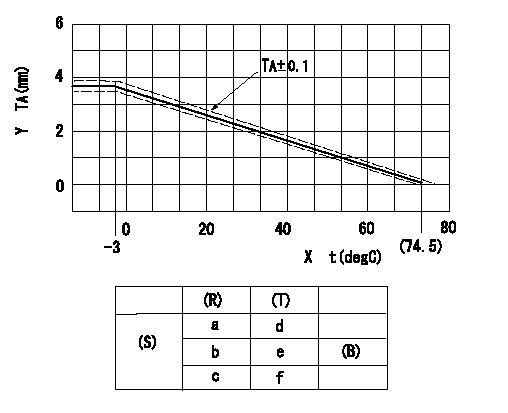
Adjustment of the timer advance angle
1. Determine the timer advance angle using the graph (graph TA).
X:Temperature t (deg C)
Y:Timer stroke TA (mm)
(S) Cold advance
(R) Cooling water temperature (deg C)
(T) Timer piston stroke (mm)
(B) Standard point
----------
TA=-0.053t+3.881 -3degC<=t<=20degC TA=-0.0517t+3.854 20degC<=t
----------
a=76.5++degC b=20degC c=-3degC d=0mm e=2.82+-0.4mm f=4.04+-0.6mm
----------
TA=-0.053t+3.881 -3degC<=t<=20degC TA=-0.0517t+3.854 20degC<=t
----------
a=76.5++degC b=20degC c=-3degC d=0mm e=2.82+-0.4mm f=4.04+-0.6mm
0000001901 STARTING I/Q ADJUSTMENT
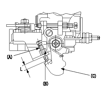
Starting Q decrease lever adjustment
Adjust using the screw (A) so that the standards are satisfied, then fix using the nut (B).
Screw (A) protrusion: L
(B) Nut (SW10, T1 after completing adjustment)
(C) Stop lever
----------
L=7.4~11.1mm T1=6~9N-m(0.6~0.9kgf-m)
----------
L=7.4~11.1mm
----------
L=7.4~11.1mm T1=6~9N-m(0.6~0.9kgf-m)
----------
L=7.4~11.1mm
0000002001 TAMPER PROOF
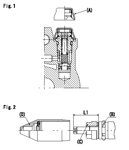
Tamperproof installation procedure
A:Cap
B:Rubber vibration damper
C:Nut
D:Cap
L1:Inspection dimension
Fig. 1 Regulating valve seal
1) Insert the cap A horizontally (press fit).
2) After insertion (press-fitting), tighten the cap to torque T1, and confirm that it is not pulled out at load F1.
Fig.2 Full load adjusting screw
1) Confirm the position of the rubber vibration damper (B) and then tighten nut (C) to the torque T2.
----------
L1=23~28mm F1=49N(5kgf) T1=4.9N-m(0.5kgf-m) T2=7~9N-m(0.7~0.9kgf-m)
----------
L1=23~28mm
----------
L1=23~28mm F1=49N(5kgf) T1=4.9N-m(0.5kgf-m) T2=7~9N-m(0.7~0.9kgf-m)
----------
L1=23~28mm
Information:
Driver Techniques
The manner in which a vehicle is driven can have a dramatic effect on fuel consumption. Operators can maximize fuel economy and engine life by practicing the techniques of using minimum power and low engine rpm. The following tips can optimize fuel economy by making maximum use of the potential efficiency of the engine and vehicle.The 3176 can be programmed to ensure that the engine and vehicle are operated within specific limits for maximum fuel economy. (Refer to topic, Customer Specified Parameters, in this publication for information.)Caterpillar engines are designed to operate at lower engine rpm (speed) and have demonstrated excellent fuel savings and longer service life when operated in this manner.Starting Out
This truck engine does not require long warm-up times that waste fuel. Below 63°F (17°C), the 3176 system automatically idles at 1000 rpm. It takes just a few minutes in the summer and a bit longer in the winter to warm up the mechanical engine, and for the 3176 engine to reduce engine rpm to the programmed low idle rpm.A load can be applied to the engine after normal oil pressure is reached and the water temperature gauge begins to rise. To get the vehicle in motion, use a gear that will result in a smooth, easy start without increasing engine speed above low idle or slipping the clutch. Engage the clutch smoothly. Interrupted and jerky clutch engagement put stress on the drive train and wastes fuel.Keep engine rpm (speed) at a minimum. Use just enough rpm to pick up the next gear. This technique is called progressive shifting. It can improve fuel consumption and will not harm the engine.Progressive Shifting
Drive line efficiency is best in the low to mid rpm range (1100 to 1600 rpm) of the engine due to reduced frictional losses of the engine, transmission and rear axles. When accelerating under normal level road conditions, the engine should be operated in this most efficient rpm range by using only enough power to pick up the next higher gear. This technique of upshifting at the lowest possible rpm is called progressive shifting.Progressive shifting also reduces the time to accelerate to the desired vehicle speed. Top gear is reached sooner because engine rpm does not have to fall off as far to synchronize the gears of the transmission. The key to progressive shifting is to use minimum rpm, minimum power and upshift early while accelerating the truck.The 3176 can be programmed to limit engine acceleration above pre-programmed engine rpm settings. This feature encourages the operator to practice progressive shifting techniques.Refer to Driving Techniques for Maximum Fuel Economy, form LEDT5092 for more information.Cruising Speed
It's a simple fact that the faster a vehicle is driven, the more fuel it will consume. A few miles per hour (kilometers per hour) can make a significant difference in fuel economy.Increasing cruising speed from 55 to 65 mph (88 to 104 km/h) will increase fuel consumption of a typical class 8 truck approximately 1.0 mpg (0.4 km/L). A practice of
Have questions with 104747-7080?
Group cross 104747-7080 ZEXEL
Komatsu
104747-7080
6273711120
INJECTION-PUMP ASSEMBLY
P162/CUMM
P162/CUMM