Information injection-pump assembly
ZEXEL
104747-7070
1047477070
KOMATSU
6273711210
6273711210
Rating:
Cross reference number
ZEXEL
104747-7070
1047477070
KOMATSU
6273711210
6273711210
Zexel num
Bosch num
Firm num
Name
104747-7070
6273711210 KOMATSU
INJECTION-PUMP ASSEMBLY
P162/CUMM
P162/CUMM
Calibration Data:
Adjustment conditions
Test oil
1404 Test oil ISO4113orSAEJ967d
1404 Test oil ISO4113orSAEJ967d
Test oil temperature
degC
45
45
50
Nozzle
105780-0060
Bosch type code
NP-DN0SD1510
Nozzle holder
105780-2150
Opening pressure
MPa
13
13
13.3
Opening pressure
kgf/cm2
133
133
136
Injection pipe
157805-7320
Injection pipe
Inside diameter - outside diameter - length (mm) mm 2-6-450
Inside diameter - outside diameter - length (mm) mm 2-6-450
Joint assembly
157641-4720
Tube assembly
157641-4020
Transfer pump pressure
kPa
20
20
20
Transfer pump pressure
kgf/cm2
0.2
0.2
0.2
Direction of rotation (viewed from drive side)
Right R
Right R
Injection timing adjustment
Pump speed
r/min
900
900
900
Average injection quantity
mm3/st.
61.8
61.3
62.3
Difference in delivery
mm3/st.
5
Basic
*
Oil temperature
degC
50
48
52
Injection timing adjustment_02
Pump speed
r/min
500
500
500
Average injection quantity
mm3/st.
52.6
48.1
57.1
Oil temperature
degC
48
46
50
Injection timing adjustment_03
Pump speed
r/min
800
800
800
Average injection quantity
mm3/st.
62.6
58.6
66.6
Oil temperature
degC
50
48
52
Injection timing adjustment_04
Pump speed
r/min
900
900
900
Average injection quantity
mm3/st.
61.8
60.3
63.3
Difference in delivery
mm3/st.
5.5
Basic
*
Oil temperature
degC
50
48
52
Injection timing adjustment_05
Pump speed
r/min
1100
1100
1100
Average injection quantity
mm3/st.
56.6
52.6
60.6
Oil temperature
degC
50
48
52
Injection quantity adjustment
Pump speed
r/min
1225
1225
1225
Average injection quantity
mm3/st.
10.7
7.7
13.7
Difference in delivery
mm3/st.
3
Basic
*
Oil temperature
degC
50
48
52
Injection quantity adjustment_02
Pump speed
r/min
1400
1400
1400
Average injection quantity
mm3/st.
3
Oil temperature
degC
50
48
52
Injection quantity adjustment_03
Pump speed
r/min
1225
1225
1225
Average injection quantity
mm3/st.
10.7
6.2
15.2
Basic
*
Oil temperature
degC
50
48
52
Governor adjustment
Pump speed
r/min
400
400
400
Average injection quantity
mm3/st.
8.6
6.6
10.6
Difference in delivery
mm3/st.
2
Basic
*
Oil temperature
degC
48
46
50
Governor adjustment_02
Pump speed
r/min
400
400
400
Average injection quantity
mm3/st.
8.6
6.1
11.1
Difference in delivery
mm3/st.
2.5
Basic
*
Oil temperature
degC
48
46
50
Timer adjustment
Pump speed
r/min
100
100
100
Average injection quantity
mm3/st.
80
75
85
Basic
*
Oil temperature
degC
48
46
50
Remarks
IDLE
IDLE
Timer adjustment_02
Pump speed
r/min
100
100
100
Average injection quantity
mm3/st.
80
75
85
Oil temperature
degC
48
46
50
Remarks
IDLE
IDLE
Speed control lever angle
Pump speed
r/min
400
400
400
Average injection quantity
mm3/st.
0
0
0
Oil temperature
degC
48
46
50
Remarks
Magnet OFF at idling position
Magnet OFF at idling position
0000000901
Pump speed
r/min
1100
1100
1100
Overflow quantity
cm3/min
415
285
545
Oil temperature
degC
50
48
52
Stop lever angle
Pump speed
r/min
1100
1100
1100
Pressure
kPa
520
500
540
Pressure
kgf/cm2
5.3
5.1
5.5
Basic
*
Oil temperature
degC
50
48
52
Stop lever angle_02
Pump speed
r/min
900
900
900
Pressure
kPa
411
362
460
Pressure
kgf/cm2
4.5
4
5
Oil temperature
degC
50
48
52
Stop lever angle_03
Pump speed
r/min
1000
1000
1000
Pressure
kPa
481
432
530
Pressure
kgf/cm2
4.9
4.4
5.4
Oil temperature
degC
50
48
52
Stop lever angle_04
Pump speed
r/min
1100
1100
1100
Pressure
kPa
520
491
549
Pressure
kgf/cm2
5.3
5
5.6
Basic
*
Oil temperature
degC
50
48
52
0000001101
Pump speed
r/min
1100
1100
1100
Timer stroke
mm
1.3
1.1
1.5
Basic
*
Oil temperature
degC
50
48
52
_02
Pump speed
r/min
900
900
900
Timer stroke
mm
0.5
Oil temperature
degC
50
48
52
_03
Pump speed
r/min
1100
1100
1100
Timer stroke
mm
1.3
1
1.6
Basic
*
Oil temperature
degC
50
48
52
0000001201
Max. applied voltage
V
16
16
16
Test voltage
V
25
24
26
Timing setting
K dimension
mm
3.3
3.2
3.4
KF dimension
mm
5.8
5.7
5.9
MS dimension
mm
2
1.9
2.1
Control lever angle alpha
deg.
16
12
20
Control lever angle beta
deg.
30
25
35
Test data Ex:
0000001801 STARTING I/Q ADJUSTMENT
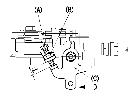
Starting Q decrease lever adjustment
Adjust using the screw (A) so that the standards are satisfied, then fix using the nut (B).
Screw B protrusion: L
A = starting Q adjusting bolt
B = starting Q adjusting nut (Tightening torque T)
C = starting Q adjusting lever
D = adjust with the lever pushed in the direction of the arrow.
----------
L=6.3~10.7mm T=6~9Nm(0.6~0.9kgfm)
----------
L=6.3~10.7mm
----------
L=6.3~10.7mm T=6~9Nm(0.6~0.9kgfm)
----------
L=6.3~10.7mm
0000001901 W-CSD ADJUSTMENT
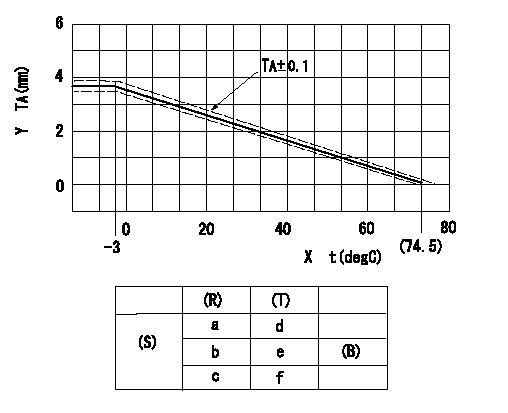
Adjustment of the W-CSD
Adjustment of the timer advance angle
1. Determine the timer advance angle using the graph (graph TA).
X:Temperature t (deg C)
Y:Timer stroke TA (mm)
(S) Cold advance
(R) Cooling water temperature (deg C)
(T) Timer piston stroke (mm)
(B) Standard point
----------
TA=-0.053t+3.881 -3degC<=t<=20degC TA=-0.0517t+3.854 20degC<=t
----------
a=76.5++degC b=20degC c=-3degC d=0mm e=2.82+-0.4mm f=4.04+-0.6mm
----------
TA=-0.053t+3.881 -3degC<=t<=20degC TA=-0.0517t+3.854 20degC<=t
----------
a=76.5++degC b=20degC c=-3degC d=0mm e=2.82+-0.4mm f=4.04+-0.6mm
0000002001 TAMPER PROOF
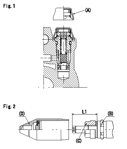
Tamperproof installation procedure
A:Cap
B:Rubber vibration damper
C:Nut
D:Cap
L1:Inspection dimension
Fig. 1 Regulating valve seal
1) Insert the cap A horizontally (press fit).
2) After insertion (press-fitting), tighten the cap to torque T1, and confirm that it is not pulled out at load F1.
Fig.2 Full load adjusting screw
1) Confirm the position of the rubber vibration damper (B) and then tighten nut (C) to the torque T2.
----------
L1=23~28mm F1=49N(5kgf) T1=4.9N-m(0.5kgf-m) T2=7~9N-m(0.7~0.9kgf-m)
----------
L1=23~28mm
----------
L1=23~28mm F1=49N(5kgf) T1=4.9N-m(0.5kgf-m) T2=7~9N-m(0.7~0.9kgf-m)
----------
L1=23~28mm
Information:
Under the Hood Inspection
For maximum service life of your truck engine, make a thorough under the hood inspection before starting the engine. Look for such items as oil or coolant leaks, loose bolts, worn belts and trash build-up. Remove trash build-up and have repairs made as needed.Perform required Daily maintenance before starting the engine.
Each time any significant quantity of oil (or other fluid) is spilled on or near the engine it should be cleaned up. Accumulated grease and oil on an engine is a fire hazard. Remove this debris with steam cleaning or high pressure water at PM Level 2 or every 6000 hours.Wipe clean all fittings, caps and plugs before servicing.
Starting the Engine
Do not store starting fluid containers in the cab. Failure to do so, could result in an explosion and/or fire and possible personal injury.If equipped with an electrically or fuel ignited manifold heater, DO NOT use ether.
Startability will be improved at temperatures below +32°F (0°C) by the use of a starting aid (ether) or use of a cylinder block coolant heater or other means to heat the crankcase oil. This will help alleviate white smoke and misfire during cold weather start-up.Use ether when temperatures are below 32°F (0°C) for cold weather starting purposes only.
When using starting fluid, follow the manufacturer's instructions carefully, use it sparingly and spray it ONLY WHILE CRANKING THE ENGINE. Excessive ether can cause piston and ring damage.Use ether for cold starting purposes only.
If the engine fails to start within 30 seconds, release the starter switch and wait two minutes to allow the starter motor to cool before using it again.Start the engine using the following procedure:1. Place the transmission in NEUTRAL and disengage the flywheel clutch (if equipped) to remove the transmission drag and prevent movement of the truck.Depressing the clutch in cold weather can mean the difference between starting and not starting. Depressing the clutch in warm weather produces faster starts and reduces battery drain.2. Turn the ignition switch to the ON position and push the crank button or turn the ignition switch to the START position.3. Crank the engine. If the engine fails to start in 30 seconds, release the starting (ignition) switch and wait two minutes to allow the starter motor to cool before using it again.
Do not increase engine speed until the oil pressure gauge indicates normal. Oil pressure should raise within 15 seconds after the engine starts.If oil pressure is not indicated on gauge within 15 seconds, do not drive the truck. Stop the engine, investigate and correct the cause.
4. Allow the engine to idle three to five minutes, or until the water temperature gauge has begun to rise. Check all gauges during the warm-up period.5. Check fuel level gauge. Do not fill fuel tank to top. Fuel expands as it gets warm and may overflow.Starting With Jumper Cables
When boost starting an engine, follow the instructions to properly start the engine. This engine may be equipped with a 12 or 24 volt starting system. Use only
Have questions with 104747-7070?
Group cross 104747-7070 ZEXEL
Komatsu
104747-7070
6273711210
INJECTION-PUMP ASSEMBLY
P162/CUMM
P162/CUMM