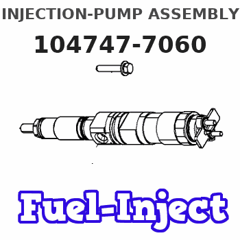
Information injection-pump assembly
ZEXEL
104747-7060
1047477060
KOMATSU
6273711110
6273711110
Rating:
Cross reference number
ZEXEL
104747-7060
1047477060
KOMATSU
6273711110
6273711110
Zexel num
Bosch num
Firm num
Name
104747-7060
6273711110 KOMATSU
INJECTION-PUMP ASSEMBLY
P162/CUMM
P162/CUMM
Calibration Data:
Adjustment conditions
Test oil
1404 Test oil ISO4113orSAEJ967d
1404 Test oil ISO4113orSAEJ967d
Test oil temperature
degC
45
45
50
Nozzle
105780-0060
Bosch type code
NP-DN0SD1510
Nozzle holder
105780-2150
Opening pressure
MPa
13
13
13.3
Opening pressure
kgf/cm2
133
133
136
Injection pipe
157805-7320
Injection pipe
Inside diameter - outside diameter - length (mm) mm 2-6-450
Inside diameter - outside diameter - length (mm) mm 2-6-450
Joint assembly
157641-4720
Tube assembly
157641-4020
Transfer pump pressure
kPa
20
20
20
Transfer pump pressure
kgf/cm2
0.2
0.2
0.2
Direction of rotation (viewed from drive side)
Right R
Right R
Injection timing adjustment
Pump speed
r/min
900
900
900
Average injection quantity
mm3/st.
61.8
61.3
62.3
Difference in delivery
mm3/st.
5
Basic
*
Oil temperature
degC
50
48
52
Injection timing adjustment_02
Pump speed
r/min
500
500
500
Average injection quantity
mm3/st.
52.6
48.1
57.1
Oil temperature
degC
48
46
50
Injection timing adjustment_03
Pump speed
r/min
800
800
800
Average injection quantity
mm3/st.
62.6
58.6
66.6
Oil temperature
degC
50
48
52
Injection timing adjustment_04
Pump speed
r/min
900
900
900
Average injection quantity
mm3/st.
61.8
60.3
63.3
Difference in delivery
mm3/st.
5.5
Basic
*
Oil temperature
degC
50
48
52
Injection timing adjustment_05
Pump speed
r/min
1100
1100
1100
Average injection quantity
mm3/st.
56.6
52.6
60.6
Oil temperature
degC
50
48
52
Injection quantity adjustment
Pump speed
r/min
1225
1225
1225
Average injection quantity
mm3/st.
10.7
7.7
13.7
Difference in delivery
mm3/st.
3
Basic
*
Oil temperature
degC
50
48
52
Injection quantity adjustment_02
Pump speed
r/min
1400
1400
1400
Average injection quantity
mm3/st.
3
Oil temperature
degC
50
48
52
Injection quantity adjustment_03
Pump speed
r/min
1225
1225
1225
Average injection quantity
mm3/st.
10.7
6.2
15.2
Basic
*
Oil temperature
degC
50
48
52
Governor adjustment
Pump speed
r/min
400
400
400
Average injection quantity
mm3/st.
8.6
6.6
10.6
Difference in delivery
mm3/st.
2
Basic
*
Oil temperature
degC
48
46
50
Governor adjustment_02
Pump speed
r/min
400
400
400
Average injection quantity
mm3/st.
8.6
6.1
11.1
Difference in delivery
mm3/st.
2.5
Basic
*
Oil temperature
degC
48
46
50
Timer adjustment
Pump speed
r/min
100
100
100
Average injection quantity
mm3/st.
80
75
85
Basic
*
Oil temperature
degC
48
46
50
Remarks
IDLE
IDLE
Timer adjustment_02
Pump speed
r/min
100
100
100
Average injection quantity
mm3/st.
80
75
85
Oil temperature
degC
48
46
50
Remarks
IDLE
IDLE
Speed control lever angle
Pump speed
r/min
400
400
400
Average injection quantity
mm3/st.
0
0
0
Oil temperature
degC
48
46
50
Remarks
Magnet OFF at idling position
Magnet OFF at idling position
0000000901
Pump speed
r/min
1100
1100
1100
Overflow quantity
cm3/min
415
285
545
Oil temperature
degC
50
48
52
Stop lever angle
Pump speed
r/min
1100
1100
1100
Pressure
kPa
520
500
540
Pressure
kgf/cm2
5.3
5.1
5.5
Basic
*
Oil temperature
degC
50
48
52
Stop lever angle_02
Pump speed
r/min
900
900
900
Pressure
kPa
441
392
490
Pressure
kgf/cm2
4.5
4
5
Oil temperature
degC
50
48
52
Stop lever angle_03
Pump speed
r/min
1000
1000
1000
Pressure
kPa
481
432
530
Pressure
kgf/cm2
4.9
4.4
5.4
Oil temperature
degC
50
48
52
Stop lever angle_04
Pump speed
r/min
1100
1100
1100
Pressure
kPa
520
491
549
Pressure
kgf/cm2
5.3
5
5.6
Basic
*
Oil temperature
degC
50
48
52
0000001101
Pump speed
r/min
1100
1100
1100
Timer stroke
mm
1.3
1.1
1.5
Basic
*
Oil temperature
degC
50
48
52
_02
Pump speed
r/min
900
900
900
Timer stroke
mm
0.5
Oil temperature
degC
50
48
52
_03
Pump speed
r/min
1100
1100
1100
Timer stroke
mm
1.3
1
1.6
Basic
*
Oil temperature
degC
50
48
52
0000001201
Max. applied voltage
V
8
8
8
Test voltage
V
13
12
14
Timing setting
K dimension
mm
3.3
3.2
3.4
KF dimension
mm
5.8
5.7
5.9
MS dimension
mm
2
1.9
2.1
Control lever angle alpha
deg.
16
12
20
Control lever angle beta
deg.
30
25
35
Test data Ex:
0000001801 STARTING I/Q ADJUSTMENT
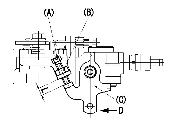
Starting Q decrease lever adjustment
Adjust using the screw (A) so that the standards are satisfied, then fix using the nut (B).
Screw B protrusion: L
A = starting Q adjusting bolt
B = starting Q adjusting nut (Tightening torque T)
C = starting Q adjusting lever
D = adjust with the lever pushed in the direction of the arrow.
----------
L=6.3~10.7mm T=6~9Nm(0.6~0.9kgfm)
----------
L=6.3~10.7mm
----------
L=6.3~10.7mm T=6~9Nm(0.6~0.9kgfm)
----------
L=6.3~10.7mm
0000001901 W-CSD ADJUSTMENT
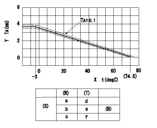
Adjustment of the W-CSD
Adjustment of the timer advance angle
1. Determine the timer advance angle using the graph (graph TA).
X:Temperature t (deg C)
Y:Timer stroke TA (mm)
(S) Cold advance
(R) Cooling water temperature (deg C)
(T) Timer piston stroke (mm)
(B) Standard point
----------
TA=-0.053t+3.881 -3degC<=t<=20degC TA=-0.0517t+3.854 20degC<=t
----------
a=76.5++degC b=20degC c=-3degC d=0mm e=2.82+-0.4mm f=4.04+-0.6mm
----------
TA=-0.053t+3.881 -3degC<=t<=20degC TA=-0.0517t+3.854 20degC<=t
----------
a=76.5++degC b=20degC c=-3degC d=0mm e=2.82+-0.4mm f=4.04+-0.6mm
0000002001 TAMPER PROOF
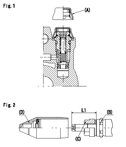
Tamperproof installation procedure
A:Cap
B:Rubber vibration damper
C:Nut
D:Cap
L1:Inspection dimension
Fig. 1 Regulating valve seal
1) Insert the cap A horizontally (press fit).
2) After insertion (press-fitting), tighten the cap to torque T1, and confirm that it is not pulled out at load F1.
Fig.2 Full load adjusting screw
1) Confirm the position of the rubber vibration damper (B) and then tighten nut (C) to the torque T2.
----------
L1=23~28mm F1=49N(5kgf) T1=4.9N-m(0.5kgf-m) T2=7~9N-m(0.7~0.9kgf-m)
----------
L1=23~28mm
----------
L1=23~28mm F1=49N(5kgf) T1=4.9N-m(0.5kgf-m) T2=7~9N-m(0.7~0.9kgf-m)
----------
L1=23~28mm
Information:
PTO Mode Speed Limit (PTO)- Maximum vehicle speed at which the PTO Governor will function (between 0 and 15 mph [0 and 24 km/h]). If vehicle speed signal exceeds the programmed value, the control will exit the PTO Mode. PTO Mode RPM Limit (PTO RPM)- Maximum engine rpm attainable in the PTO Mode. The rpm limits are between 600 and 2300 rpm. PTO Engine Speed Ramp Rate- Engine rpm (speed) rate of increase. This parameter determines ACCEL, DECEL and RESUME PTO Engine rates of increase/decrease. The programmable limits are between 50 rpm/second and 500 rpm/second. Low Gears #1 RPM Limit (LoGr #1)- Engine speed is limited below Low Gear #1 Turn Off Speed. The engine will hesitate at this speed then allow slow acceleration up to Top Engine Limit (TEL). This is to encourage shifting to the next higher gear. The limits are between 1100 and 2300 rpm. Low Gears #1 Turn Off (Lo Gr Off)- The vehicle speed at which LoGr #1 RPM Limit is no longer in effect (turns off between 3 and 30 mph [5 and 48 km/h]). This parameter must be matched with Low Gear #1 RPM Limit to the specific drive train for best performance. Low Gears #2 RPM Limit (LoGr #2)- Similar to Low Gears #1 RPM Limit and typically programmed at a slightly higher rpm. The limits are between 1100 and 2300 rpm. Low Gears #2 Turn Off (LoGr TO)- Similar to Low Gears #1 Turn Off and typically programmed at a slightly higher rpm. The limits are between 5 and 50 mph [8 and 80 km/h]). High Gears RPM Limit (HiGr RPM)- The rpm limit when the vehicle speed is above High Gear Turn On Speed. This is a "hard" limit; the engine will not power above this limit to encourage shifting up into overdrive or top gear. The limits are between 1300 and 2300 rpm. High Gear Turn On Speed (HiGr On)- Vehicle speed where High Gear RPM Limit turns on. This parameter must be matched to the specific drive train for best performance. The limits are between 30 and 127 mph (48 and 204 km/h). Top Engine Limit (TEL)- Maximum allowable engine rpm when the engine is under load. The engine will still achieve Rated rpm (speed) under no load conditions. This parameter is dependent upon Rating Number, with some Rating Numbers allowing no or little variation. The limits are between 1600 and 3000 rpm. Low Engine Idle rpm- Minimum programmed engine rpm (between 600 and 750 rpm). Vehicle Speed Limit- Top vehicle speed the ECM will permit. The ECM will shut off fuel above this speed. The limits are between 30 and 127 mph (48 and 204 km/h and/or gear limit of vehicle. Engine RPM at Vehicle Speed Limit (Eng RPM at VSL)- The maximum rpm that the engine will operate when the vehicle speed signal reaches VSL, or when the ECM detects a vehicle speed signal problem (the ECM will limit engine to this rpm
Have questions with 104747-7060?
Group cross 104747-7060 ZEXEL
Komatsu
104747-7060
6273711110
INJECTION-PUMP ASSEMBLY
P162/CUMM
P162/CUMM