Information injection-pump assembly
ZEXEL
104747-7030
1047477030
KOMATSU
6272711220
6272711220
Rating:
Cross reference number
ZEXEL
104747-7030
1047477030
KOMATSU
6272711220
6272711220
Zexel num
Bosch num
Firm num
Name
104747-7030
6272711220 KOMATSU
INJECTION-PUMP ASSEMBLY
P161/CUMM
P161/CUMM
Calibration Data:
Adjustment conditions
Test oil
1404 Test oil ISO4113orSAEJ967d
1404 Test oil ISO4113orSAEJ967d
Test oil temperature
degC
45
45
50
Nozzle
105780-0060
Bosch type code
NP-DN0SD1510
Nozzle holder
105780-2150
Opening pressure
MPa
13
13
13.3
Opening pressure
kgf/cm2
133
133
136
Injection pipe
157805-7320
Injection pipe
Inside diameter - outside diameter - length (mm) mm 2-6-450
Inside diameter - outside diameter - length (mm) mm 2-6-450
Joint assembly
157641-4720
Tube assembly
157641-4020
Transfer pump pressure
kPa
20
20
20
Transfer pump pressure
kgf/cm2
0.2
0.2
0.2
Direction of rotation (viewed from drive side)
Right R
Right R
Injection timing adjustment
Pump speed
r/min
900
900
900
Average injection quantity
mm3/st.
56.2
55.7
56.7
Difference in delivery
mm3/st.
4.5
Basic
*
Oil temperature
degC
50
48
52
Injection timing adjustment_02
Pump speed
r/min
500
500
500
Average injection quantity
mm3/st.
52.3
47.8
56.8
Oil temperature
degC
48
46
50
Injection timing adjustment_03
Pump speed
r/min
800
800
800
Average injection quantity
mm3/st.
57.5
53.5
61.5
Oil temperature
degC
50
48
52
Injection timing adjustment_04
Pump speed
r/min
900
900
900
Average injection quantity
mm3/st.
56.2
54.7
57.7
Difference in delivery
mm3/st.
5
Basic
*
Oil temperature
degC
50
48
52
Injection timing adjustment_05
Pump speed
r/min
1100
1100
1100
Average injection quantity
mm3/st.
51.5
47.5
55.5
Oil temperature
degC
50
48
52
Injection quantity adjustment
Pump speed
r/min
1225
1225
1225
Average injection quantity
mm3/st.
11.9
8.9
14.9
Difference in delivery
mm3/st.
3.5
Basic
*
Oil temperature
degC
50
48
52
Injection quantity adjustment_02
Pump speed
r/min
1400
1400
1400
Average injection quantity
mm3/st.
3
Oil temperature
degC
50
48
52
Injection quantity adjustment_03
Pump speed
r/min
1225
1225
1225
Average injection quantity
mm3/st.
11.9
7.4
16.4
Basic
*
Oil temperature
degC
50
48
52
Governor adjustment
Pump speed
r/min
400
400
400
Average injection quantity
mm3/st.
8.6
6.6
10.6
Difference in delivery
mm3/st.
2
Basic
*
Oil temperature
degC
48
46
50
Governor adjustment_02
Pump speed
r/min
400
400
400
Average injection quantity
mm3/st.
8.6
6.1
11.1
Difference in delivery
mm3/st.
2.5
Basic
*
Oil temperature
degC
48
46
50
Timer adjustment
Pump speed
r/min
100
100
100
Average injection quantity
mm3/st.
80
75
85
Basic
*
Oil temperature
degC
48
46
50
Remarks
IDLE
IDLE
Timer adjustment_02
Pump speed
r/min
100
100
100
Average injection quantity
mm3/st.
80
75
85
Oil temperature
degC
48
46
50
Remarks
IDLE
IDLE
Speed control lever angle
Pump speed
r/min
400
400
400
Average injection quantity
mm3/st.
0
0
0
Oil temperature
degC
48
46
50
Remarks
Magnet OFF at idling position
Magnet OFF at idling position
0000000901
Pump speed
r/min
1100
1100
1100
Overflow quantity
cm3/min
400
270
530
Oil temperature
degC
50
48
52
Stop lever angle
Pump speed
r/min
1100
1100
1100
Pressure
kPa
500
480
520
Pressure
kgf/cm2
5.1
4.9
5.3
Basic
*
Oil temperature
degC
50
48
52
Stop lever angle_02
Pump speed
r/min
700
700
700
Pressure
kPa
392
343
441
Pressure
kgf/cm2
4
3.5
4.5
Oil temperature
degC
50
48
52
Stop lever angle_03
Pump speed
r/min
800
800
800
Pressure
kPa
422
373
471
Pressure
kgf/cm2
4.3
3.8
4.8
Oil temperature
degC
50
48
52
Stop lever angle_04
Pump speed
r/min
1100
1100
1100
Pressure
kPa
500
471
529
Pressure
kgf/cm2
5.1
4.8
5.4
Basic
*
Oil temperature
degC
50
48
52
0000001101
Pump speed
r/min
1100
1100
1100
Timer stroke
mm
2.8
2.6
3
Basic
*
Oil temperature
degC
50
48
52
_02
Pump speed
r/min
800
800
800
Timer stroke
mm
1.1
0.6
1.6
Oil temperature
degC
50
48
52
_03
Pump speed
r/min
1100
1100
1100
Timer stroke
mm
2.8
2.5
3.1
Basic
*
Oil temperature
degC
50
48
52
0000001201
Max. applied voltage
V
16
16
16
Test voltage
V
25
24
26
0000001401
Pump speed
r/min
1100
1100
1100
Average injection quantity
mm3/st.
40
39
41
Timer stroke TA
mm
2
1.8
2.2
Timer stroke variation dT
mm
0.8
0.8
0.8
Basic
*
Oil temperature
degC
50
48
52
_02
Pump speed
r/min
1100
1100
1100
Average injection quantity
mm3/st.
40
38.5
41.5
Timer stroke TA
mm
2
1.7
2.3
Timer stroke variation dT
mm
0.8
0.8
0.8
Basic
*
Oil temperature
degC
50
48
52
_03
Pump speed
r/min
1100
1100
1100
Average injection quantity
mm3/st.
30
28
32
Timer stroke TA
mm
1.1
0.6
1.6
Timer stroke variation dT
mm
1.7
1.7
1.7
Oil temperature
degC
50
48
52
Timing setting
K dimension
mm
3.3
3.2
3.4
KF dimension
mm
5.8
5.7
5.9
MS dimension
mm
2
1.9
2.1
Control lever angle alpha
deg.
16
12
20
Control lever angle beta
deg.
30
25
35
Test data Ex:
0000001801 W-CSD ADJUSTMENT
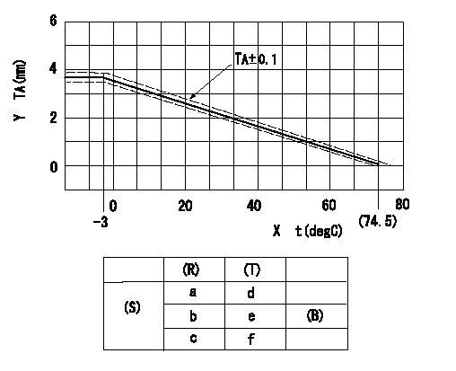
Adjustment of the W-CSD
Adjustment of the timer advance angle
1. Determine the timer advance angle using the graph (graph TA).
X:Temperature t (deg C)
Y:Timer stroke TA (mm)
(S) Cold advance
(R) Cooling water temperature (deg C)
(T) Timer piston stroke (mm)
(B) Standard point
----------
TA=-0.053t+3.881 -3degC<=t<=20degC TA=-0.0517t+3.854 20degC<=t
----------
a=76.5++degC b=20degC c=-3degC d=0mm e=2.82+-0.4mm f=4.04+-0.6mm
----------
TA=-0.053t+3.881 -3degC<=t<=20degC TA=-0.0517t+3.854 20degC<=t
----------
a=76.5++degC b=20degC c=-3degC d=0mm e=2.82+-0.4mm f=4.04+-0.6mm
0000001901 STARTING I/Q ADJUSTMENT
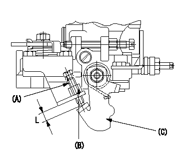
Starting Q decrease lever adjustment
Adjust using the screw (A) so that the standards are satisfied, then fix using the nut (B).
Screw (A) protrusion: L
(B) Nut (SW10, T1 after completing adjustment)
(C) Stop lever
----------
L=7.4~11.1mm T1=6~9N-m(0.6~0.9kgf-m)
----------
L=7.4~11.1mm
----------
L=7.4~11.1mm T1=6~9N-m(0.6~0.9kgf-m)
----------
L=7.4~11.1mm
0000002001 TAMPER PROOF
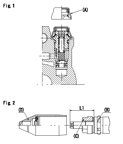
Tamperproof installation procedure
A:Cap
B:Rubber vibration damper
C:Nut
D:Cap
L1:Inspection dimension
Fig. 1 Regulating valve seal
1) Insert the cap A horizontally (press fit).
2) After insertion (press-fitting), tighten the cap to torque T1, and confirm that it is not pulled out at load F1.
Fig.2 Full load adjusting screw
1) Confirm the position of the rubber vibration damper (B) and then tighten nut (C) to the torque T2.
----------
L1=23~28mm F1=49N(5kgf) T1=4.9N-m(0.5kgf-m) T2=7~9N-m(0.7~0.9kgf-m)
----------
L1=23~28mm
----------
L1=23~28mm F1=49N(5kgf) T1=4.9N-m(0.5kgf-m) T2=7~9N-m(0.7~0.9kgf-m)
----------
L1=23~28mm
Information:
Torque for Standard Bolts, Nuts and Taperlock Studs
The following charts give general torques for bolts, nuts and taperlock studs of SAE Grade 5 or better quality.
Torques for Bolts and Nuts With Standard Threads
Torques for Taperlock Studs
Use these standard torque values for all fasteners unless otherwise specified in this publication or in the Service Manual.Torque for Metric Fasteners
This product uses 10.9 Grade metric fasteners.
Be very careful never to mix metric with customary (standard) fasteners. Mismatched or incorrect fasteners will cause engine damage or malfunction and may even result in personal injury.Original fasteners removed from the engine should be saved for reassembly whenever possible. If new fasteners are needed, they must be of the same size and grade as the ones that are being replaced.The material strength identification is usually shown on the bolt head by numbers (8.8, 10.9, etc.). Use these standard torque values unless otherwise specified in this publication or the Service Manual.The following charts give general torques for bolts and nuts with Metric Threads of SAE Grade 8.8 or better quality.
Torques for Bolts and Nuts with Metric Threads
Torque for Standard Hose Clamps-Worm Drive Band Type
The following chart gives the torques for initial installation of hose clamps on new hose and for reassembly or tightening of hose clamps on existing hose.
Torque for Constant Torque Hose Clamps
A constant torque hose clamp can be used in place of any standard hose clamp. Make sure the constant torque hose clamp is the same size as the standard clamp. Due to extreme temperature changes, hose will heat set. Heat setting causes hose clamps to loosen. Loose hose clamps can result in leaks. There have been reports of component failures caused by hose clamps loosening. The new, constant torque hose clamp will help prevent these failures.Each installation application can be different depending on the type of hose, fitting material and anticipated expansion or contraction of the hose and fittings. A torque wrench should be used for proper installation of the new, constant torque hose clamps. Constant torque hose clamps should be installed as follows:* To allow for maximum expansion, install clamps at 50 lb in (5.7 N m).* To allow for equal expansion and contraction, install clamps at 90 lb in (10.2 N m).* To allow for maximum contraction, install clamps at 125 lb in (14.1 N m).
Have questions with 104747-7030?
Group cross 104747-7030 ZEXEL
Komatsu
104747-7030
6272711220
INJECTION-PUMP ASSEMBLY
P161/CUMM
P161/CUMM