Information injection-pump assembly
ZEXEL
104747-7010
1047477010
KOMATSU
6272711210
6272711210

Rating:
Cross reference number
ZEXEL
104747-7010
1047477010
KOMATSU
6272711210
6272711210
Zexel num
Bosch num
Firm num
Name
104747-7010
6272711210 KOMATSU
INJECTION-PUMP ASSEMBLY
P161/CUMM
P161/CUMM
Calibration Data:
Adjustment conditions
Test oil
1404 Test oil ISO4113orSAEJ967d
1404 Test oil ISO4113orSAEJ967d
Test oil temperature
degC
45
45
50
Nozzle
105780-0060
Bosch type code
NP-DN0SD1510
Nozzle holder
105780-2150
Opening pressure
MPa
13
13
13.3
Opening pressure
kgf/cm2
133
133
136
Injection pipe
157805-7320
Injection pipe
Inside diameter - outside diameter - length (mm) mm 2-6-450
Inside diameter - outside diameter - length (mm) mm 2-6-450
Joint assembly
157641-4720
Tube assembly
157641-4020
Transfer pump pressure
kPa
20
20
20
Transfer pump pressure
kgf/cm2
0.2
0.2
0.2
Direction of rotation (viewed from drive side)
Right R
Right R
Injection timing adjustment
Pump speed
r/min
900
900
900
Average injection quantity
mm3/st.
60.2
59.7
60.7
Difference in delivery
mm3/st.
4.5
Basic
*
Oil temperature
degC
50
48
52
Injection timing adjustment_02
Pump speed
r/min
500
500
500
Average injection quantity
mm3/st.
53.6
49.1
58.1
Oil temperature
degC
48
46
50
Injection timing adjustment_03
Pump speed
r/min
800
800
800
Average injection quantity
mm3/st.
61.3
57.3
65.3
Oil temperature
degC
50
48
52
Injection timing adjustment_04
Pump speed
r/min
900
900
900
Average injection quantity
mm3/st.
60.2
58.7
61.7
Difference in delivery
mm3/st.
5
Basic
*
Oil temperature
degC
50
48
52
Injection timing adjustment_05
Pump speed
r/min
1300
1300
1300
Average injection quantity
mm3/st.
49.5
45.5
53.5
Oil temperature
degC
50
48
52
Injection quantity adjustment
Pump speed
r/min
1425
1425
1425
Average injection quantity
mm3/st.
16
13
19
Difference in delivery
mm3/st.
4.5
Basic
*
Oil temperature
degC
50
48
52
Injection quantity adjustment_02
Pump speed
r/min
1600
1600
1600
Average injection quantity
mm3/st.
3
Oil temperature
degC
50
48
52
Injection quantity adjustment_03
Pump speed
r/min
1425
1425
1425
Average injection quantity
mm3/st.
16
11.5
20.5
Basic
*
Oil temperature
degC
50
48
52
Governor adjustment
Pump speed
r/min
400
400
400
Average injection quantity
mm3/st.
8.6
6.6
10.6
Difference in delivery
mm3/st.
2
Basic
*
Oil temperature
degC
48
46
50
Governor adjustment_02
Pump speed
r/min
400
400
400
Average injection quantity
mm3/st.
8.6
6.1
11.1
Difference in delivery
mm3/st.
2.5
Basic
*
Oil temperature
degC
48
46
50
Timer adjustment
Pump speed
r/min
100
100
100
Average injection quantity
mm3/st.
80
75
85
Basic
*
Oil temperature
degC
48
46
50
Remarks
IDLE
IDLE
Timer adjustment_02
Pump speed
r/min
100
100
100
Average injection quantity
mm3/st.
80
75
85
Oil temperature
degC
48
46
50
Remarks
IDLE
IDLE
Speed control lever angle
Pump speed
r/min
400
400
400
Average injection quantity
mm3/st.
0
0
0
Oil temperature
degC
48
46
50
Remarks
Magnet OFF at idling position
Magnet OFF at idling position
0000000901
Pump speed
r/min
1300
1300
1300
Overflow quantity
cm3/min
430
300
560
Oil temperature
degC
50
48
52
Stop lever angle
Pump speed
r/min
1300
1300
1300
Pressure
kPa
559
539
579
Pressure
kgf/cm2
5.7
5.5
5.9
Basic
*
Oil temperature
degC
50
48
52
Stop lever angle_02
Pump speed
r/min
800
800
800
Pressure
kPa
422
373
471
Pressure
kgf/cm2
4.3
3.8
4.8
Oil temperature
degC
50
48
52
Stop lever angle_03
Pump speed
r/min
1100
1100
1100
Pressure
kPa
500
451
549
Pressure
kgf/cm2
5.1
4.6
5.6
Oil temperature
degC
50
48
52
Stop lever angle_04
Pump speed
r/min
1300
1300
1300
Pressure
kPa
559
530
588
Pressure
kgf/cm2
5.7
5.4
6
Basic
*
Oil temperature
degC
50
48
52
0000001101
Pump speed
r/min
1300
1300
1300
Timer stroke
mm
4.4
4.2
4.6
Basic
*
Oil temperature
degC
50
48
52
_02
Pump speed
r/min
800
800
800
Timer stroke
mm
1.6
1.1
2.1
Oil temperature
degC
50
48
52
_03
Pump speed
r/min
1300
1300
1300
Timer stroke
mm
4.4
4.1
4.7
Basic
*
Oil temperature
degC
50
48
52
0000001201
Max. applied voltage
V
16
16
16
Test voltage
V
25
24
26
0000001401
Pump speed
r/min
1300
1300
1300
Average injection quantity
mm3/st.
39
38
40
Timer stroke TA
mm
3.6
3.4
3.8
Timer stroke variation dT
mm
0.8
0.8
0.8
Basic
*
Oil temperature
degC
50
48
52
_02
Pump speed
r/min
1300
1300
1300
Average injection quantity
mm3/st.
39
37.5
40.5
Timer stroke TA
mm
3.6
3.3
3.9
Timer stroke variation dT
mm
0.8
0.8
0.8
Basic
*
Oil temperature
degC
50
48
52
_03
Pump speed
r/min
1300
1300
1300
Average injection quantity
mm3/st.
30
28
32
Timer stroke TA
mm
2.7
2.2
3.2
Timer stroke variation dT
mm
1.7
1.7
1.7
Oil temperature
degC
50
48
52
Timing setting
K dimension
mm
3.3
3.2
3.4
KF dimension
mm
5.8
5.7
5.9
MS dimension
mm
2
1.9
2.1
Control lever angle alpha
deg.
16
12
20
Control lever angle beta
deg.
33
28
38
Test data Ex:
0000001801 W-CSD ADJUSTMENT
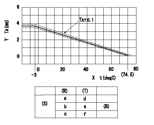
Adjustment of the W-CSD
Adjustment of the timer advance angle
1. Determine the timer advance angle using the graph (graph TA).
X:Temperature t (deg C)
Y:Timer stroke TA (mm)
(S) Cold advance
(R) Cooling water temperature (deg C)
(T) Timer piston stroke (mm)
(B) Standard point
----------
TA=-0.053t+3.881 -3degC<=t<=20degC TA=-0.0517t+3.854 20degC<=t
----------
a=76.5++degC b=20degC c=-3degC d=0mm e=2.82+-0.4mm f=4.04+-0.6mm
----------
TA=-0.053t+3.881 -3degC<=t<=20degC TA=-0.0517t+3.854 20degC<=t
----------
a=76.5++degC b=20degC c=-3degC d=0mm e=2.82+-0.4mm f=4.04+-0.6mm
0000001901 STARTING I/Q ADJUSTMENT
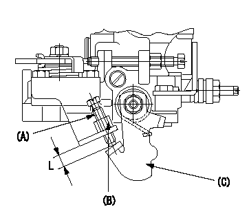
Starting Q decrease lever adjustment
Adjust using the screw (A) so that the standards are satisfied, then fix using the nut (B).
Screw (A) protrusion: L
(B) Nut (SW10, T1 after completing adjustment)
(C) Stop lever
----------
L=7.4~11.1mm T1=6~9N-m(0.6~0.9kgf-m)
----------
L=7.4~11.1mm
----------
L=7.4~11.1mm T1=6~9N-m(0.6~0.9kgf-m)
----------
L=7.4~11.1mm
0000002001 TAMPER PROOF
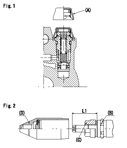
Tamperproof installation procedure
A:Cap
B:Rubber vibration damper
C:Nut
D:Cap
L1:Inspection dimension
Fig. 1 Regulating valve seal
1) Insert the cap A horizontally (press fit).
2) After insertion (press-fitting), tighten the cap to torque T1, and confirm that it is not pulled out at load F1.
Fig.2 Full load adjusting screw
1) Confirm the position of the rubber vibration damper (B) and then tighten nut (C) to the torque T2.
----------
L1=23~28mm F1=49N(5kgf) T1=4.9N-m(0.5kgf-m) T2=7~9N-m(0.7~0.9kgf-m)
----------
L1=23~28mm
----------
L1=23~28mm F1=49N(5kgf) T1=4.9N-m(0.5kgf-m) T2=7~9N-m(0.7~0.9kgf-m)
----------
L1=23~28mm
Information:
3176 ATAAC Truck Engine Model Views
Oil Filter (1), Coolant Conditioner Element (2), Thermostat Housing (3), Oil Filter (4) and Turbocharger (5).
Fuel Filter and Priming Pump (6), Electronic Governor and Personality Module (7), Crankcase Breather (8), Grounding Stud (9).Engine Information
The Caterpillar 3176 ATAAC Diesel Truck engine is an 629 cu.in. (10.3 L) displacement, 4.9 in. (125 mm) bore, 5.5 in. (140 mm) stroke, four stroke cycle, 6 cylinder engine. The firing order is 1-5-3-6-2-4 and the direction of rotation is counterclockwise, as viewed from the flywheel. The 3176 is an electronically controlled, mechanically actuated unit injector diesel engine. Timing advance is achieved by precise control of injector firing. Engine speed is controlled by adjusting the firing duration. A speed timing sensor provides information to the fuel cooled ECM (Electronic Control Module) for detection of cylinder position and engine speed.The 3176 electronic engine control system was designed to provide electronic governing, automatic air-fuel ratio control, torque rise shaping, injection timing control and system diagnostics.Additional benefits such as improved cold starting capability, tamper resistance, diagnostics, cruise control, vehicle speed limiting, progressive shift engine speed control, PTO governor and American Trucking Association (ATA) data link and an Engine Monitoring Package (if equipped) provide for additional engine fuel economy, driver comfort and serviceability.The fuel system is a mechanically actuated, electronically controlled unit injector combining the pumping, electronic fuel metering and injecting elements in a single unit to produce higher injection pressures (22,000 psi [151 600 kPa]). High injection pressures help to reduce fuel consumption and particulate emissions.The use of this type of unit injector provides total electronic control of injection timing. The injection timing is varied as a function of engine operating conditions. This optimizes the engine's performance for starting, emissions, noise, fuel consumption and driveability.The 3176 has built-in diagnostics to assure that all components are functioning and operating properly. In the event of a system component deviation from programmed limits, the operator will be alerted to the condition by a dashboard mounted CHECK ENGINE/DIAGNOSTIC lamp.A Caterpillar service tool may be used to read the numerical code of the faulty component. Intermittent faults are logged and stored in the system memory. Refer to Engine Diagnostics section of this publication for alternative methods.The cooling system consists of a gear driven centrifugal pump, with one thermostat which regulates the engine coolant water temperature, a plate type oil cooler and a radiator incorporating a shunt system.The 3176 does not have a cylinder block water cooling system. Instead, the cast water manifold in the spacer deck distributes 65% of the coolant volume to each of the cylinder liners and the remaining 35% flows directly to the cylinder head.The engine lubricating oil, which is both cooled and filtered, is supplied by a gear-type pump. Bypass valves provide unrestricted flow of lubrication oil to the engine parts when oil viscosity is high, or if either the oil cooler or the oil filter elements (paper cartridge) should become plugged.Engine efficiency, efficiency of emission controls and engine performance depend on adherence
Have questions with 104747-7010?
Group cross 104747-7010 ZEXEL
Komatsu
104747-7010
6272711210
INJECTION-PUMP ASSEMBLY
P161/CUMM
P161/CUMM