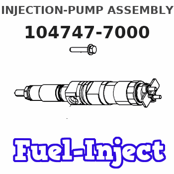
Information injection-pump assembly
ZEXEL
104747-7000
1047477000
KOMATSU
6272711110
6272711110
Rating:
Compare Prices: .
As an associate, we earn commssions on qualifying purchases through the links below

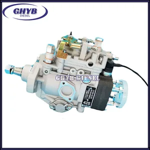
Car fuel pump assembly, Diesel Fuel Injection Pump 104747-7000 NP-VE4/10F1300RNP2625 6272-71-1110 Compatible For CUMMINS
ZTUVUNVA The design of the oil outlet is exquisite and reasonable, which avoids carbon deposition at the oil outlet and effectively prolongs the service life. || Reduce fuel consumption, improve jitter and accelerate smoothly. || The oil meter is accurate, which can solve the problems of abnormal oil consumption, misfire and no power. || Solve problems such as abnormal fuel meter data. || Sufficient oil return flow ensures stable pressure and sufficient cooling of the fuel system.
ZTUVUNVA The design of the oil outlet is exquisite and reasonable, which avoids carbon deposition at the oil outlet and effectively prolongs the service life. || Reduce fuel consumption, improve jitter and accelerate smoothly. || The oil meter is accurate, which can solve the problems of abnormal oil consumption, misfire and no power. || Solve problems such as abnormal fuel meter data. || Sufficient oil return flow ensures stable pressure and sufficient cooling of the fuel system.
Diesel Fuel Injection Pump 104747-7000 NP-VE4/10F1300RNP2625 6272-71-1110 Compatible For CUMMINS
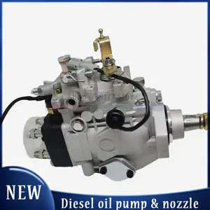
VSQQGPSV Through high-precision pressure, fuel can be fully atomized, promoting complete combustion and improving fuel economy. || High precision manufacturing processes ensure the accuracy of fuel metering and injection. || Excellent design minimizes noise and vibration during operation, providing you with a quieter and more comfortable driving experience. || A good fuel injection pump is crucial for engine power, fuel efficiency, and fuel economy. || Diesel Fuel Injection Pump 104747-7000 NP-VE4/10F1300RNP2625 6272-71-1110 Compatible For CUMMINS
VSQQGPSV Through high-precision pressure, fuel can be fully atomized, promoting complete combustion and improving fuel economy. || High precision manufacturing processes ensure the accuracy of fuel metering and injection. || Excellent design minimizes noise and vibration during operation, providing you with a quieter and more comfortable driving experience. || A good fuel injection pump is crucial for engine power, fuel efficiency, and fuel economy. || Diesel Fuel Injection Pump 104747-7000 NP-VE4/10F1300RNP2625 6272-71-1110 Compatible For CUMMINS

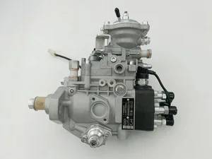
Diesel Fuel Injection Pump 104647-7000 NP-VE4/10F1300RNP2625 6272-71-1110 Compatible For CUMMINS
CFNCFJGJ [Part number] : 104647-7000 6272-71-1110 || [Easy installation] : Standard interface, easy installation, plug and play, no professional skills, easy installation. || [Durable and reliable] : After multiple tests, long life, excellent quality, and stable work in extreme environments. || [Efficient and stable] : With the support of advanced technology, fuel supply is efficient and stable, ensuring the smooth flow of vehicles. || [High quality] : The use of high-quality materials and smart design, strict testing and verification, to ensure long-term stability and high reliability.
CFNCFJGJ [Part number] : 104647-7000 6272-71-1110 || [Easy installation] : Standard interface, easy installation, plug and play, no professional skills, easy installation. || [Durable and reliable] : After multiple tests, long life, excellent quality, and stable work in extreme environments. || [Efficient and stable] : With the support of advanced technology, fuel supply is efficient and stable, ensuring the smooth flow of vehicles. || [High quality] : The use of high-quality materials and smart design, strict testing and verification, to ensure long-term stability and high reliability.
You can express buy:
USD 416.31
19-05-2025
19-05-2025
Diesel Fuel Injection Pump 104647-7000 NP-VE4/10F1300RNP2625 6272-71-1110 For CUMMINS
USD 653.93
13-05-2025
13-05-2025
Diesel Fuel VE Pumps 104647-7000 NP-VE4/10F1300RNP2625 6272-71-1110 For CUMMINS P161
USD 480.43
19-05-2025
19-05-2025
Diesel Fuel VE Pumps 104647-7000 NP-VE4/10F1300RNP2625 6272-71-1110 For CUMMINS P161
Images:
USD 416.9

[14-Jun-2025]
USD 405.71

[14-Jun-2025]
USD 414.49

[19-May-2025]
Cross reference number
ZEXEL
104747-7000
1047477000
KOMATSU
6272711110
6272711110
Zexel num
Bosch num
Firm num
Name
104747-7000
6272711110 KOMATSU
INJECTION-PUMP ASSEMBLY
P161/CUMM
P161/CUMM
Calibration Data:
Adjustment conditions
Test oil
1404 Test oil ISO4113orSAEJ967d
1404 Test oil ISO4113orSAEJ967d
Test oil temperature
degC
45
45
50
Nozzle
105780-0060
Bosch type code
NP-DN0SD1510
Nozzle holder
105780-2150
Opening pressure
MPa
13
13
13.3
Opening pressure
kgf/cm2
133
133
136
Injection pipe
157805-7320
Injection pipe
Inside diameter - outside diameter - length (mm) mm 2-6-450
Inside diameter - outside diameter - length (mm) mm 2-6-450
Joint assembly
157641-4720
Tube assembly
157641-4020
Transfer pump pressure
kPa
20
20
20
Transfer pump pressure
kgf/cm2
0.2
0.2
0.2
Direction of rotation (viewed from drive side)
Right R
Right R
Injection timing adjustment
Pump speed
r/min
900
900
900
Average injection quantity
mm3/st.
60.2
59.7
60.7
Difference in delivery
mm3/st.
4.5
Basic
*
Oil temperature
degC
50
48
52
Injection timing adjustment_02
Pump speed
r/min
500
500
500
Average injection quantity
mm3/st.
53.6
49.1
58.1
Oil temperature
degC
48
46
50
Injection timing adjustment_03
Pump speed
r/min
800
800
800
Average injection quantity
mm3/st.
61.3
57.3
65.3
Oil temperature
degC
50
48
52
Injection timing adjustment_04
Pump speed
r/min
900
900
900
Average injection quantity
mm3/st.
60.2
58.7
61.7
Difference in delivery
mm3/st.
5
Basic
*
Oil temperature
degC
50
48
52
Injection timing adjustment_05
Pump speed
r/min
1300
1300
1300
Average injection quantity
mm3/st.
49.5
45.5
53.5
Oil temperature
degC
50
48
52
Injection quantity adjustment
Pump speed
r/min
1425
1425
1425
Average injection quantity
mm3/st.
16
13
19
Difference in delivery
mm3/st.
4.5
Basic
*
Oil temperature
degC
50
48
52
Injection quantity adjustment_02
Pump speed
r/min
1600
1600
1600
Average injection quantity
mm3/st.
3
Oil temperature
degC
50
48
52
Injection quantity adjustment_03
Pump speed
r/min
1425
1425
1425
Average injection quantity
mm3/st.
16
11.5
20.5
Basic
*
Oil temperature
degC
50
48
52
Governor adjustment
Pump speed
r/min
400
400
400
Average injection quantity
mm3/st.
8.6
6.6
10.6
Difference in delivery
mm3/st.
2
Basic
*
Oil temperature
degC
48
46
50
Governor adjustment_02
Pump speed
r/min
400
400
400
Average injection quantity
mm3/st.
8.6
6.1
11.1
Difference in delivery
mm3/st.
2.5
Basic
*
Oil temperature
degC
48
46
50
Timer adjustment
Pump speed
r/min
100
100
100
Average injection quantity
mm3/st.
80
75
85
Basic
*
Oil temperature
degC
48
46
50
Remarks
IDLE
IDLE
Timer adjustment_02
Pump speed
r/min
100
100
100
Average injection quantity
mm3/st.
80
75
85
Oil temperature
degC
48
46
50
Remarks
IDLE
IDLE
Speed control lever angle
Pump speed
r/min
400
400
400
Average injection quantity
mm3/st.
0
0
0
Oil temperature
degC
48
46
50
Remarks
Magnet OFF at idling position
Magnet OFF at idling position
0000000901
Pump speed
r/min
1300
1300
1300
Overflow quantity
cm3/min
430
300
560
Oil temperature
degC
50
48
52
Stop lever angle
Pump speed
r/min
1300
1300
1300
Pressure
kPa
559
539
579
Pressure
kgf/cm2
5.7
5.5
5.9
Basic
*
Oil temperature
degC
50
48
52
Stop lever angle_02
Pump speed
r/min
800
800
800
Pressure
kPa
422
373
471
Pressure
kgf/cm2
4.3
3.8
4.8
Oil temperature
degC
50
48
52
Stop lever angle_03
Pump speed
r/min
1100
1100
1100
Pressure
kPa
500
451
549
Pressure
kgf/cm2
5.1
4.6
5.6
Oil temperature
degC
50
48
52
Stop lever angle_04
Pump speed
r/min
1300
1300
1300
Pressure
kPa
559
530
588
Pressure
kgf/cm2
5.7
5.4
6
Basic
*
Oil temperature
degC
50
48
52
0000001101
Pump speed
r/min
1300
1300
1300
Timer stroke
mm
4.4
4.2
4.6
Basic
*
Oil temperature
degC
50
48
52
_02
Pump speed
r/min
800
800
800
Timer stroke
mm
1.6
1.1
2.1
Oil temperature
degC
50
48
52
_03
Pump speed
r/min
1300
1300
1300
Timer stroke
mm
4.4
4.1
4.7
Basic
*
Oil temperature
degC
50
48
52
0000001201
Max. applied voltage
V
8
8
8
Test voltage
V
13
12
14
0000001401
Pump speed
r/min
1300
1300
1300
Average injection quantity
mm3/st.
39
38
40
Timer stroke TA
mm
3.6
3.4
3.8
Timer stroke variation dT
mm
0.8
0.8
0.8
Basic
*
Oil temperature
degC
50
48
52
_02
Pump speed
r/min
1300
1300
1300
Average injection quantity
mm3/st.
39
37.5
40.5
Timer stroke TA
mm
3.6
3.3
3.9
Timer stroke variation dT
mm
0.8
0.8
0.8
Basic
*
Oil temperature
degC
50
48
52
_03
Pump speed
r/min
1300
1300
1300
Average injection quantity
mm3/st.
30
28
32
Timer stroke TA
mm
2.7
2.2
3.2
Timer stroke variation dT
mm
1.7
1.7
1.7
Oil temperature
degC
50
48
52
Timing setting
K dimension
mm
3.3
3.2
3.4
KF dimension
mm
5.8
5.7
5.9
MS dimension
mm
2
1.9
2.1
Control lever angle alpha
deg.
16
12
20
Control lever angle beta
deg.
33
28
38
Test data Ex:
0000001801 W-CSD ADJUSTMENT
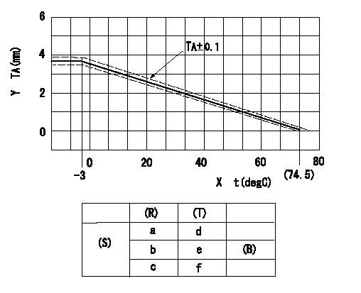
Adjustment of the W-CSD
Adjustment of the timer advance angle
1. Determine the timer advance angle using the graph (graph TA).
X:Temperature t (deg C)
Y:Timer stroke TA (mm)
(S) Cold advance
(R) Cooling water temperature (deg C)
(T) Timer piston stroke (mm)
(B) Standard point
----------
TA=-0.053t+3.881 -3degC<=t<=20degC TA=-0.0517t+3.854 20degC<=t
----------
a=76.5++degC b=20degC c=-3degC d=0mm e=2.82+-0.4mm f=4.04+-0.6mm
----------
TA=-0.053t+3.881 -3degC<=t<=20degC TA=-0.0517t+3.854 20degC<=t
----------
a=76.5++degC b=20degC c=-3degC d=0mm e=2.82+-0.4mm f=4.04+-0.6mm
0000001901 STARTING I/Q ADJUSTMENT
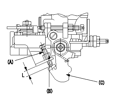
Starting Q decrease lever adjustment
Adjust using the screw (A) so that the standards are satisfied, then fix using the nut (B).
Screw (A) protrusion: L
(B) Nut (SW10, T1 after completing adjustment)
(C) Stop lever
----------
L=7.4~11.1mm T1=6~9N-m(0.6~0.9kgf-m)
----------
L=7.4~11.1mm
----------
L=7.4~11.1mm T1=6~9N-m(0.6~0.9kgf-m)
----------
L=7.4~11.1mm
0000002001 TAMPER PROOF
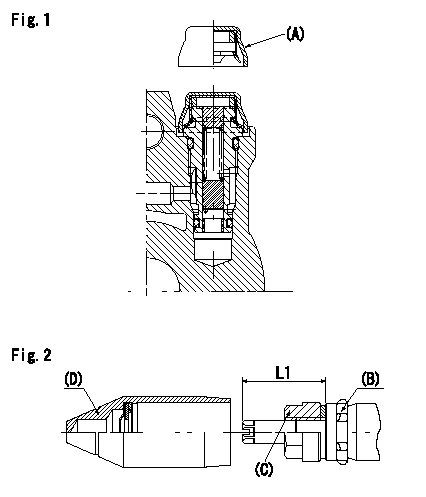
Tamperproof installation procedure
A:Cap
B:Rubber vibration damper
C:Nut
D:Cap
L1:Inspection dimension
Fig. 1 Regulating valve seal
1) Insert the cap A horizontally (press fit).
2) After insertion (press-fitting), tighten the cap to torque T1, and confirm that it is not pulled out at load F1.
Fig.2 Full load adjusting screw
1) Confirm the position of the rubber vibration damper (B) and then tighten nut (C) to the torque T2.
----------
L1=23~28mm F1=49N(5kgf) T1=4.9N-m(0.5kgf-m) T2=7~9N-m(0.7~0.9kgf-m)
----------
L1=23~28mm
----------
L1=23~28mm F1=49N(5kgf) T1=4.9N-m(0.5kgf-m) T2=7~9N-m(0.7~0.9kgf-m)
----------
L1=23~28mm
Information:
Burn Prevention
Do not touch any part of an operating engine. Allow the engine to cool before any repair or maintenance is performed on the engine.Relieve all pressure in air, oil, fuel or cooling systems before any lines, fittings or related items are disconnected or removed.Coolant
To prevent personal injury, do not step up on engine to remove the filler cap, if applicable. Use an adequate ladder.At operating temperature, the engine coolant is hot and under pressure. The radiator and all lines to heaters or the engine contain hot water. When pressure is relieved rapidly, this hot water can turn into steam.Allow cooling system components to cool before draining. Any contact with hot water or steam can cause severe burns.Check the coolant level only after the engine has been stopped and the filler cap is cool enough to remove with your bare hand. Remove the cooling system filler cap slowly to relieve pressure.Cooling system supplemental additive contains alkali. To prevent personal injury, avoid contact with the skin and eyes and do not drink.Oils
Hot oil and components can cause personal injury. Do not allow hot oil or components to contact the skin.Batteries
Battery electrolyte contains acid and can cause injury. Avoid contact with the skin and eyes. Wash hands after touching batteries and connectors. Use of gloves is recommended. Always wear protective glasses when working with batteries.Batteries give off flammable fumes which can explode. Always thaw a frozen battery before jump starting. Frozen batteries can explode. Do not smoke when observing the battery electrolyte levels.Fire or Explosion Prevention
Determine whether the engine will be operated in an environment in which combustible gases could be drawn through the air inlet system. These gases could cause the engine to overspeed, which in turn could seriously damage the engine and result in bodily injury or property damage.If your application involves the presence of combustible gases, consult your Caterpillar dealer to obtain additional information concerning protection devices suitable for the application involved.Inhaling freon gas through a lit cigarette or other smoking method, or inhaling fumes released from a flame contacting freon could cause bodily harm or death. Do not smoke when servicing, charging or working around air conditioners or where freon gas may be present.All fuels, most lubricants and some coolant mixtures are flammable. Diesel fuel is flammable. Gasoline is flammable. The mixture of diesel and gasoline fumes are extremely explosive.Do not smoke while refueling or in a refueling area.Do not smoke in areas where batteries are charged, or where flammable materials are stored.Keep all fuels and lubricants stored in properly marked containers and away from all unauthorized persons.Store all oily rags or other flammable material in a protective container, in a safe place.Do not weld or flame cut on pipes or tubes that contain flammable fluids. Clean them thoroughly with nonflammable solvent before welding or flame cutting on them.Remove all flammable materials such as fuel, oil and other debris before they accumulate on the truck engine.Do not expose the engine to flames, burning brush, etc., if
Have questions with 104747-7000?
Group cross 104747-7000 ZEXEL
Komatsu
104747-7000
6272711110
INJECTION-PUMP ASSEMBLY
P161/CUMM
P161/CUMM