Information injection-pump assembly
ZEXEL
104746-6601
1047466601

Rating:
Cross reference number
ZEXEL
104746-6601
1047466601
Zexel num
Bosch num
Firm num
Name
104746-6601
INJECTION-PUMP ASSEMBLY
Calibration Data:
Adjustment conditions
Test oil
1404 Test oil ISO4113orSAEJ967d
1404 Test oil ISO4113orSAEJ967d
Test oil temperature
degC
45
45
50
Nozzle
105780-0060
Bosch type code
NP-DN0SD1510
Nozzle holder
105780-2150
Opening pressure
MPa
13
13
13.3
Opening pressure
kgf/cm2
133
133
136
Injection pipe
157805-7320
Injection pipe
Inside diameter - outside diameter - length (mm) mm 2-6-450
Inside diameter - outside diameter - length (mm) mm 2-6-450
Joint assembly
157641-4720
Tube assembly
157641-4020
Transfer pump pressure
kPa
20
20
20
Transfer pump pressure
kgf/cm2
0.2
0.2
0.2
Direction of rotation (viewed from drive side)
Left L
Left L
Timer measuring device installation position
Low pressure side LOW PRESSURE SIDE
Low pressure side LOW PRESSURE SIDE
Injection timing adjustment
Pump speed
r/min
500
500
500
Boost pressure
kPa
0
0
0
Boost pressure
mmHg
0
0
0
Average injection quantity
mm3/st.
60.5
60
61
Difference in delivery
mm3/st.
5
Basic
*
Oil temperature
degC
48
46
50
Remarks
NA
NA
Injection timing adjustment_02
Pump speed
r/min
800
800
800
Boost pressure
kPa
52
50.7
53.3
Boost pressure
mmHg
390
380
400
Average injection quantity
mm3/st.
67.4
66.9
67.9
Difference in delivery
mm3/st.
5.5
Basic
*
Oil temperature
degC
50
48
52
Remarks
CBS
CBS
Injection timing adjustment_03
Pump speed
r/min
800
800
800
Boost pressure
kPa
80
78.7
81.3
Boost pressure
mmHg
600
590
610
Average injection quantity
mm3/st.
76.8
76.3
77.3
Difference in delivery
mm3/st.
6
Basic
*
Oil temperature
degC
50
48
52
Remarks
Full
Full
Injection timing adjustment_04
Pump speed
r/min
500
500
500
Boost pressure
kPa
0
0
0
Boost pressure
mmHg
0
0
0
Average injection quantity
mm3/st.
60.5
59.5
61.5
Difference in delivery
mm3/st.
5
Basic
*
Oil temperature
degC
48
46
50
Remarks
NA
NA
Injection timing adjustment_05
Pump speed
r/min
800
800
800
Boost pressure
kPa
52
50.7
53.3
Boost pressure
mmHg
390
380
400
Average injection quantity
mm3/st.
67.4
66.4
68.4
Difference in delivery
mm3/st.
5.5
Basic
*
Oil temperature
degC
50
48
52
Remarks
CBS
CBS
Injection timing adjustment_06
Pump speed
r/min
800
800
800
Boost pressure
kPa
80
78.7
81.3
Boost pressure
mmHg
600
590
610
Average injection quantity
mm3/st.
76.8
75.8
77.8
Difference in delivery
mm3/st.
6
Basic
*
Oil temperature
degC
50
48
52
Remarks
Full
Full
Injection timing adjustment_07
Pump speed
r/min
1000
1000
1000
Boost pressure
kPa
80
78.7
81.3
Boost pressure
mmHg
600
590
610
Average injection quantity
mm3/st.
83.8
77.3
90.3
Oil temperature
degC
50
48
52
Injection timing adjustment_08
Pump speed
r/min
1250
1250
1250
Boost pressure
kPa
80
78.7
81.3
Boost pressure
mmHg
600
590
610
Average injection quantity
mm3/st.
91.5
85
98
Oil temperature
degC
50
48
52
Injection timing adjustment_09
Pump speed
r/min
1700
1700
1700
Boost pressure
kPa
80
78.7
81.3
Boost pressure
mmHg
600
590
610
Average injection quantity
mm3/st.
105.7
99.2
112.2
Oil temperature
degC
50
48
52
Injection quantity adjustment
Pump speed
r/min
2075
2075
2075
Boost pressure
kPa
80
78.7
81.3
Boost pressure
mmHg
600
590
610
Average injection quantity
mm3/st.
34
31
37
Difference in delivery
mm3/st.
7
Basic
*
Oil temperature
degC
52
50
54
Injection quantity adjustment_02
Pump speed
r/min
2300
2300
2300
Boost pressure
kPa
80
78.7
81.3
Boost pressure
mmHg
600
590
610
Average injection quantity
mm3/st.
3
Oil temperature
degC
52
50
54
Injection quantity adjustment_03
Pump speed
r/min
2075
2075
2075
Boost pressure
kPa
80
78.7
81.3
Boost pressure
mmHg
600
590
610
Average injection quantity
mm3/st.
34
31
37
Difference in delivery
mm3/st.
7
Basic
*
Oil temperature
degC
52
50
54
Governor adjustment
Pump speed
r/min
375
375
375
Boost pressure
kPa
0
0
0
Boost pressure
mmHg
0
0
0
Average injection quantity
mm3/st.
13.9
11.9
15.9
Difference in delivery
mm3/st.
2
Basic
*
Oil temperature
degC
48
46
50
Governor adjustment_02
Pump speed
r/min
375
375
375
Boost pressure
kPa
0
0
0
Boost pressure
mmHg
0
0
0
Average injection quantity
mm3/st.
13.9
11.9
15.9
Difference in delivery
mm3/st.
2
Basic
*
Oil temperature
degC
48
46
50
Timer adjustment
Pump speed
r/min
100
100
100
Boost pressure
kPa
0
0
0
Boost pressure
mmHg
0
0
0
Average injection quantity
mm3/st.
60
60
100
Basic
*
Oil temperature
degC
48
46
50
Remarks
Full
Full
Timer adjustment_02
Pump speed
r/min
100
100
100
Boost pressure
kPa
0
0
0
Boost pressure
mmHg
0
0
0
Average injection quantity
mm3/st.
60
60
100
Oil temperature
degC
48
46
50
Remarks
Full
Full
Speed control lever angle
Pump speed
r/min
375
375
375
Boost pressure
kPa
0
0
0
Boost pressure
mmHg
0
0
0
Average injection quantity
mm3/st.
0
0
0
Oil temperature
degC
48
46
50
Remarks
Magnet OFF at idling position
Magnet OFF at idling position
0000000901
Pump speed
r/min
1350
1350
1350
Boost pressure
kPa
80
78.7
81.3
Boost pressure
mmHg
600
590
610
Overflow quantity
cm3/min
1080
850
1310
Oil temperature
degC
50
48
52
Stop lever angle
Pump speed
r/min
1350
1350
1350
Boost pressure
kPa
80
78.7
81.3
Boost pressure
mmHg
600
590
610
Pressure
kPa
471
442
500
Pressure
kgf/cm2
4.8
4.5
5.1
Basic
*
Oil temperature
degC
50
48
52
Stop lever angle_02
Pump speed
r/min
1020
1020
1020
Boost pressure
kPa
80
78.7
81.3
Boost pressure
mmHg
600
590
610
Pressure
kPa
353
314
392
Pressure
kgf/cm2
3.6
3.2
4
Oil temperature
degC
50
48
52
Stop lever angle_03
Pump speed
r/min
1250
1250
1250
Boost pressure
kPa
80
78.7
81.3
Boost pressure
mmHg
600
590
610
Pressure
kPa
432
393
471
Pressure
kgf/cm2
4.4
4
4.8
Oil temperature
degC
50
48
52
Stop lever angle_04
Pump speed
r/min
1350
1350
1350
Boost pressure
kPa
80
78.7
81.3
Boost pressure
mmHg
600
590
610
Pressure
kPa
471
442
500
Pressure
kgf/cm2
4.8
4.5
5.1
Basic
*
Oil temperature
degC
50
48
52
Stop lever angle_05
Pump speed
r/min
1500
1500
1500
Boost pressure
kPa
80
78.7
81.3
Boost pressure
mmHg
600
590
610
Pressure
kPa
510
471
549
Pressure
kgf/cm2
5.2
4.8
5.6
Oil temperature
degC
50
48
52
Stop lever angle_06
Pump speed
r/min
1800
1800
1800
Boost pressure
kPa
80
78.7
81.3
Boost pressure
mmHg
600
590
610
Pressure
kPa
628
589
667
Pressure
kgf/cm2
6.4
6
6.8
Oil temperature
degC
50
48
52
0000001101
Pump speed
r/min
1350
1350
1350
Boost pressure
kPa
80
78.7
81.3
Boost pressure
mmHg
600
590
610
Timer stroke
mm
1.8
1.6
2
Basic
*
Oil temperature
degC
50
48
52
_02
Pump speed
r/min
1020
1020
1020
Boost pressure
kPa
80
78.7
81.3
Boost pressure
mmHg
600
590
610
Timer stroke
mm
0.5
Oil temperature
degC
50
48
52
_03
Pump speed
r/min
1350
1350
1350
Boost pressure
kPa
80
78.7
81.3
Boost pressure
mmHg
600
590
610
Timer stroke
mm
1.8
1.6
2
Basic
*
Oil temperature
degC
50
48
52
_04
Pump speed
r/min
1500
1500
1500
Boost pressure
kPa
80
78.7
81.3
Boost pressure
mmHg
600
590
610
Timer stroke
mm
3
2.6
3.4
Oil temperature
degC
50
48
52
_05
Pump speed
r/min
1800
1800
1800
Boost pressure
kPa
80
78.7
81.3
Boost pressure
mmHg
600
590
610
Timer stroke
mm
4.5
4.2
4.9
Oil temperature
degC
50
48
52
0000001201
Max. applied voltage
V
8
8
8
Test voltage
V
13
12
14
Timing setting
K dimension
mm
3.6
3.5
3.7
KF dimension
mm
7.76
7.66
7.86
MS dimension
mm
0.8
0.7
0.9
BCS stroke
mm
2.6
2.4
2.8
Pre-stroke
mm
0.2
0.18
0.22
Control lever angle alpha
deg.
18
14
22
Control lever angle beta
deg.
37
32
42
Test data Ex:
0000001601 BOOST COMPENSATOR ADJUSTMENT

BCS adjustment procedure
1. At full boost pressure, set so that the full injection quantity is within the specifications (adjusting point).
2. Perform boost compensator intermediate operation point adjustment (pump speed N1, boost pressure P1).
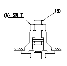
3. When injection quantity at boost pressure P2 and pump speed N2 is not as specified, loosen nut (A) and adjust position of screw (B) so that injection quantity is as specified. The screw position should be within +-1 turn of initial position.
4. The nut tightening torque is T.
----------
N1=800r/min N2=500r/min P1=52.0kPa(390mmHg) P2=0kPa(0mmHg) T=6~9N-m(0.6~0.9kgf-m)
----------
SW=10mm T=6~9N-m(0.6~0.9kgf-m)
----------
N1=800r/min N2=500r/min P1=52.0kPa(390mmHg) P2=0kPa(0mmHg) T=6~9N-m(0.6~0.9kgf-m)
----------
SW=10mm T=6~9N-m(0.6~0.9kgf-m)
0000001801 POTENTIOMETER ADJUSTMENT

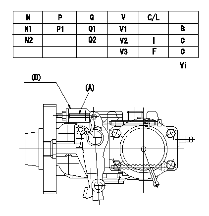
Potentiometer adjusting specifications (oval)
N:Pump speed
Q:Injection quantity
P:Boost pressure
V:Output voltage
C/L: control lever position
I:Idle
F:Full lever position
B:Adjusting point
C:Checking point
D:Bracket (shape may differ)
Adjusting method (applied voltage Vi, dummy bolt method)
1. Hold the dummy bolt (A) against the control lever at position N = N1 and Q = Q1 and fix using the lock nut.
2. At potentiometer adjustment, with the control lever contacting the dummy bolt, adjust the potentiometer so that the output voltage is V1.
3. After completing adjustment, remove the dummy bolt (A) and confirm that the potentiometer output voltage is within the adjustment specifications when the control lever is in the idle position.
(A): Dummy bolt and nut part number 146526-3300 (bolt) corresponding to 42 (mm).
Corresponding to 013020-6040 (nut)
----------
N1=1080r/min Q1=27.5+-1.0mm3/st V1=3.56+-0.03V Vi=10V
----------
N1=1080r/min N2=375r/min P1=0kPa(0mmHg) Q1=27.5+-1.0mm3/st Q2=13.9+-2.0mm3/st V1=3.56+-0.03V V2=(0.93+-0.45V) V3=(7.10+-0.83V) Vi=10V
----------
N1=1080r/min Q1=27.5+-1.0mm3/st V1=3.56+-0.03V Vi=10V
----------
N1=1080r/min N2=375r/min P1=0kPa(0mmHg) Q1=27.5+-1.0mm3/st Q2=13.9+-2.0mm3/st V1=3.56+-0.03V V2=(0.93+-0.45V) V3=(7.10+-0.83V) Vi=10V
Information:
Caterpillar Diesel Truck Engines can operate effectively in cold weather, however, engine operation in cold weather is dependent on the type of fuel used and how well the fuel moves through fuel related components. The purpose of this section is to explain some of the problems and steps that can be taken to minimize fuel problems during cold weather operation when the engine area is colder than 5°C (40°F).Fuel And The Effect From Cold Weather
The two types of diesel fuel available for your engine are typically grades No. 1 and No. 2. Although No. 2 diesel fuel is the most commonly used fuel, No. 1 diesel fuel or a blend of No. 1 and No.2, is the fuel that is best suited for cold weather operation.During cold weather operation, it may be necessary for you to use No. 2 diesel fuel since quantities of No. 1 diesel fuel are limited and generally are only available during the winter months and in the colder climates.There are two major differences between No. 1 and No. 2 diesel fuel. No. 1 diesel fuel has a lower cloud point and a lower pour point.The cloud point is the temperature at which a cloud or haze of wax crystals will begin to form in the fuel and cause fuel filters to plug. The pour point is the temperature which diesel fuel will begin to thicken and be more resistant to flow through fuel pumps and lines.Be aware of these fuel values when purchasing your diesel fuel and anticipate the average outside (ambient) temperature for the area your engine will be operating. Engines fueled in one climate may not operate satisfactorily if moved to another because of problems that result from cold weather. The average No. 1 diesel fuel has a lower kJ (BTU) (heat content) rating per unit volume of fuel than the average No. 2 diesel fuel. When using No. 1 diesel fuel, you may notice a drop in power and fuel efficiency, but should not experience any other operating effects.Before troubleshooting for low power or poor performance in winter months, check the type of fuel being used.The use of starting aids, engine oil pan heaters, engine coolant heaters, fuel heaters and fuel line insulation also provide a means of minimizing starting and fuel problems in cold weather when No. 2 diesel fuel is used.Fuel Related Components In Cold Weather
PEEC Fuel Cooling
Fuel Cooled PEEC ECMThe PEEC electronic control module is fuel cooled. Fuel is routed from the tank, to a primary fuel filter, through the transfer pump, then through cored passages in the electronic control module housing, on to the secondary fuel filter, and finally to the injection pump.Inlet fuel temperature to the transfer pump must never exceed 149°F (65°C). Fuel temperatures in excess of this temperature reduce the life of the electronics, reduce the life of the transfer pump check valves, and reduce engine power availability.Fuel Heaters
Fuel heaters prevent plugging of the fuel filters in cold weather due to waxing. Non-thermostatically
Have questions with 104746-6601?
Group cross 104746-6601 ZEXEL
Isuzu
104746-6601
INJECTION-PUMP ASSEMBLY