Information injection-pump assembly
ZEXEL
104746-6591
1047466591
ISUZU
8971918611
8971918611
Rating:
Cross reference number
ZEXEL
104746-6591
1047466591
ISUZU
8971918611
8971918611
Zexel num
Bosch num
Firm num
Name
Calibration Data:
Adjustment conditions
Test oil
1404 Test oil ISO4113orSAEJ967d
1404 Test oil ISO4113orSAEJ967d
Test oil temperature
degC
45
45
50
Nozzle
105780-0060
Bosch type code
NP-DN0SD1510
Nozzle holder
105780-2150
Opening pressure
MPa
13
13
13.3
Opening pressure
kgf/cm2
133
133
136
Injection pipe
157805-7320
Injection pipe
Inside diameter - outside diameter - length (mm) mm 2-6-450
Inside diameter - outside diameter - length (mm) mm 2-6-450
Joint assembly
157641-4720
Tube assembly
157641-4020
Transfer pump pressure
kPa
20
20
20
Transfer pump pressure
kgf/cm2
0.2
0.2
0.2
Direction of rotation (viewed from drive side)
Left L
Left L
Injection timing adjustment
Pump speed
r/min
1225
1225
1225
Average injection quantity
mm3/st.
58.1
57.6
58.6
Difference in delivery
mm3/st.
5
Basic
*
Oil temperature
degC
50
48
52
Injection timing adjustment_02
Pump speed
r/min
500
500
500
Average injection quantity
mm3/st.
33.1
29.6
36.6
Oil temperature
degC
48
46
50
Injection timing adjustment_03
Pump speed
r/min
750
750
750
Average injection quantity
mm3/st.
44.2
40.7
47.7
Oil temperature
degC
50
48
52
Injection timing adjustment_04
Pump speed
r/min
1225
1225
1225
Average injection quantity
mm3/st.
58.1
57.1
59.1
Difference in delivery
mm3/st.
5
Basic
*
Oil temperature
degC
50
48
52
Injection timing adjustment_05
Pump speed
r/min
1900
1900
1900
Average injection quantity
mm3/st.
64.3
60.3
68.3
Oil temperature
degC
50
48
52
Injection quantity adjustment
Pump speed
r/min
2350
2350
2350
Average injection quantity
mm3/st.
33.6
30.6
36.6
Difference in delivery
mm3/st.
6.5
Basic
*
Oil temperature
degC
52
50
54
Injection quantity adjustment_02
Pump speed
r/min
2700
2700
2700
Average injection quantity
mm3/st.
5
Oil temperature
degC
55
52
58
Injection quantity adjustment_03
Pump speed
r/min
2350
2350
2350
Average injection quantity
mm3/st.
33.6
30.6
36.6
Difference in delivery
mm3/st.
6.5
Basic
*
Oil temperature
degC
52
50
54
Governor adjustment
Pump speed
r/min
425
425
425
Average injection quantity
mm3/st.
8
6
10
Difference in delivery
mm3/st.
2
Basic
*
Oil temperature
degC
48
46
50
Governor adjustment_02
Pump speed
r/min
425
425
425
Average injection quantity
mm3/st.
8
6
10
Difference in delivery
mm3/st.
2
Basic
*
Oil temperature
degC
48
46
50
Timer adjustment
Pump speed
r/min
100
100
100
Average injection quantity
mm3/st.
60
60
100
Basic
*
Oil temperature
degC
48
46
50
Remarks
Full
Full
Timer adjustment_02
Pump speed
r/min
100
100
100
Average injection quantity
mm3/st.
60
60
100
Oil temperature
degC
48
46
50
Remarks
Full
Full
Speed control lever angle
Pump speed
r/min
375
375
375
Average injection quantity
mm3/st.
0
0
0
Oil temperature
degC
48
46
50
Remarks
Magnet OFF at idling position
Magnet OFF at idling position
0000000901
Pump speed
r/min
1500
1500
1500
Overflow quantity
cm3/min
630
500
760
Oil temperature
degC
50
48
52
Stop lever angle
Pump speed
r/min
1500
1500
1500
Pressure
kPa
412
392
432
Pressure
kgf/cm2
4.2
4
4.4
Basic
*
Oil temperature
degC
50
48
52
Stop lever angle_02
Pump speed
r/min
1500
1500
1500
Pressure
kPa
412
392
432
Pressure
kgf/cm2
4.2
4
4.4
Basic
*
Oil temperature
degC
50
48
52
0000001101
Pump speed
r/min
1500
1500
1500
Timer stroke
mm
2.7
2.5
2.9
Basic
*
Oil temperature
degC
50
48
52
_02
Pump speed
r/min
1000
1000
1000
Timer stroke
mm
0.5
Oil temperature
degC
50
48
52
_03
Pump speed
r/min
1500
1500
1500
Timer stroke
mm
2.7
2.5
2.9
Basic
*
Oil temperature
degC
50
48
52
_04
Pump speed
r/min
1700
1700
1700
Timer stroke
mm
3.9
3.5
4.3
Oil temperature
degC
50
48
52
_05
Pump speed
r/min
2050
2050
2050
Timer stroke
mm
5.3
5
5.7
Oil temperature
degC
52
50
54
0000001201
Max. applied voltage
V
8
8
8
Test voltage
V
13
12
14
Timing setting
K dimension
mm
3.1
3
3.2
KF dimension
mm
5.5
5.4
5.6
MS dimension
mm
0.8
0.7
0.9
Pre-stroke
mm
0.45
0.43
0.47
Control lever angle alpha
deg.
18
14
22
Control lever angle beta
deg.
35
30
40
Test data Ex:
0000001801 POTENTIOMETER ADJUSTMENT

A:Adjusting point
B:Confirmation point
C:Lever position
Vi:Applied voltage
V:Output voltage
C1:Idle
C2:Full speed
----------
----------
V1=1.2+-0.03V V2=(7.03+-0.86)V V3=10V V4=10V
----------
----------
V1=1.2+-0.03V V2=(7.03+-0.86)V V3=10V V4=10V
0000001901 V-FICD ADJUSTMENT
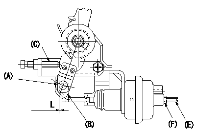
Adjustment of the V-FICD
1. After installing the V-FICD, apply P1 (kPa) {P2 (mmHg)} to the actuator and confirm that it moves through its full stroke.
2. After release, confirm that the clearance between (A) and (B) is L (mm).
----------
L=1+1(mm) P1=-53.3(kPa) P2=-400(mmHg)
----------
L=1+1(mm)
----------
L=1+1(mm) P1=-53.3(kPa) P2=-400(mmHg)
----------
L=1+1(mm)
0000002001 A/T PLATE ADJUSTMENT
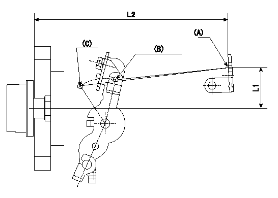
A/T plate adjustment
Adjust the A/T plate (A) so that (A)(C) - (A)(B) = L3 when the control lever is moved from the idle position (B) to the full speed position (C), then fix.
(B) Idle position
(C) Full
----------
L3=34+-1mm
----------
L1=41mm L2=173.2mm SW=SW8 T=3.4~4.9N-m(0.35~0.5kgf-m)
----------
L3=34+-1mm
----------
L1=41mm L2=173.2mm SW=SW8 T=3.4~4.9N-m(0.35~0.5kgf-m)
Information:
Until recently, engine maintenance and repair management involved changing the oil when it was convenient and repairing the engine when it was damaged. This seemed to be the accepted way of managing a maintenance operation.However, due to a variety of circumstances, freight hauling jobs became increasingly competitive. This competitiveness caused users to look for ways to prolong equipment life and lower operating costs so that they could be competitive when bidding jobs.To assist Caterpillar Truck Engine users in prolonging engine life and reducing operating costs, the Value Planned Repair approach to engine maintenance was developed.The Value Planned Repair approach can be tailored for any engine. This approach, when properly structured, outlines every maintenance and repair service required to support an engine from the day it enters service until the day it is retired.To ensure the repair is performed efficiently and expediently, the Value Planned Repair concept approaches a given repair in three basic steps: 1. Repair determination2. Evaluation of repair options3. Selection of the most appropriate optionThe Value Planned Repair approach addresses: * Services required to maintain an engine at optimum efficiency.* Scheduled maintenance, repairs and overhauls to minimize unscheduled downtime.* Preplanned repairs and overhauls that can be flatrated, putting you in charge of costs.* Repair or overhaul options designed to restore the engine to proper operating condition.* Repair or overhaul options designed to renew the engine if a failure has occurred.Part of the Value Planned Repair approach is the repair before failure concept. The objective of the repair before failure concept is to repair the engine before a failure takes place. The fact that a failure has not taken place makes the repair before failure concept more economical since a high degree of parts such as pistons, liners, valves, etc., and major castings such as cylinder blocks, cylinder heads, etc., can be reused.Also, an extensive internal cleaning of the engine, which is labor intensive, is eliminated because a debris-generating failure has not taken place.The best part of the repair before failure concept is that unscheduled downtime is minimized and in most cases eliminated.Because the repair or overhaul can be scheduled, it allows the user to adjust his operation accordingly.The overall benefit to a customer who repairs an engine before failure is that the customer and not the engine is in control of the repairs required.To stress the importance of the Value Planned Repair approach, please consider the following example that reflects the difference in the cost of a before failure repair versus the cost of an after failure repair.The cost to repair a turbocharger after it fails is approximately five times more than the cost of repairing a turbocharger before it fails.However, if parts from a damaged turbocharger enters the engine, then the cost to repair your engine could be as high as 10 times or more the cost of repairing a turbocharger before it fails.By subscribing to the Value Planned Repair approach, you can avoid spending money on costly repairs that should have been prevented.Caterpillar strongly