Information injection-pump assembly
ZEXEL
104746-6231
1047466231

Rating:
Cross reference number
ZEXEL
104746-6231
1047466231
Zexel num
Bosch num
Firm num
Name
104746-6231
INJECTION-PUMP ASSEMBLY
Calibration Data:
Adjustment conditions
Test oil
1404 Test oil ISO4113orSAEJ967d
1404 Test oil ISO4113orSAEJ967d
Test oil temperature
degC
45
45
50
Nozzle
105780-0060
Bosch type code
NP-DN0SD1510
Nozzle holder
105780-2150
Opening pressure
MPa
13
13
13.3
Opening pressure
kgf/cm2
133
133
136
Injection pipe
157805-7320
Injection pipe
Inside diameter - outside diameter - length (mm) mm 2-6-450
Inside diameter - outside diameter - length (mm) mm 2-6-450
Joint assembly
157641-4720
Tube assembly
157641-4020
Transfer pump pressure
kPa
20
20
20
Transfer pump pressure
kgf/cm2
0.2
0.2
0.2
Direction of rotation (viewed from drive side)
Left L
Left L
Injection timing adjustment
Pump speed
r/min
1150
1150
1150
Average injection quantity
mm3/st.
51.4
50.9
51.9
Difference in delivery
mm3/st.
4
Basic
*
Oil temperature
degC
50
48
52
Injection timing adjustment_02
Pump speed
r/min
500
500
500
Average injection quantity
mm3/st.
30.3
26.8
33.8
Oil temperature
degC
48
46
50
Injection timing adjustment_03
Pump speed
r/min
750
750
750
Average injection quantity
mm3/st.
33.9
30.4
37.4
Oil temperature
degC
50
48
52
Injection timing adjustment_04
Pump speed
r/min
1150
1150
1150
Average injection quantity
mm3/st.
51.4
50.4
52.4
Difference in delivery
mm3/st.
4
Basic
*
Oil temperature
degC
50
48
52
Injection timing adjustment_05
Pump speed
r/min
2050
2050
2050
Average injection quantity
mm3/st.
58.3
53.8
62.8
Oil temperature
degC
52
50
54
Injection quantity adjustment
Pump speed
r/min
2350
2350
2350
Average injection quantity
mm3/st.
40.6
37.6
43.6
Difference in delivery
mm3/st.
8
Basic
*
Oil temperature
degC
52
50
54
Injection quantity adjustment_02
Pump speed
r/min
2700
2700
2700
Average injection quantity
mm3/st.
12
Oil temperature
degC
55
52
58
Injection quantity adjustment_03
Pump speed
r/min
2350
2350
2350
Average injection quantity
mm3/st.
40.6
37.6
43.6
Difference in delivery
mm3/st.
8
Basic
*
Oil temperature
degC
52
50
54
Governor adjustment
Pump speed
r/min
375
375
375
Average injection quantity
mm3/st.
8.4
6.4
10.4
Difference in delivery
mm3/st.
2
Basic
*
Oil temperature
degC
48
46
50
Governor adjustment_02
Pump speed
r/min
375
375
375
Average injection quantity
mm3/st.
8.4
6.4
10.4
Difference in delivery
mm3/st.
2
Basic
*
Oil temperature
degC
48
46
50
Timer adjustment
Pump speed
r/min
100
100
100
Average injection quantity
mm3/st.
60
60
100
Basic
*
Oil temperature
degC
48
46
50
Remarks
Full
Full
Timer adjustment_02
Pump speed
r/min
100
100
100
Average injection quantity
mm3/st.
60
60
100
Oil temperature
degC
48
46
50
Remarks
Full
Full
Speed control lever angle
Pump speed
r/min
375
375
375
Average injection quantity
mm3/st.
0
0
0
Oil temperature
degC
48
46
50
Remarks
Magnet OFF at idling position
Magnet OFF at idling position
0000000901
Pump speed
r/min
1400
1400
1400
Overflow quantity
cm3/min
370
240
500
Oil temperature
degC
50
48
52
Stop lever angle
Pump speed
r/min
1400
1400
1400
Pressure
kPa
412
392
432
Pressure
kgf/cm2
4.2
4
4.4
Basic
*
Oil temperature
degC
50
48
52
Stop lever angle_02
Pump speed
r/min
1400
1400
1400
Pressure
kPa
412
392
432
Pressure
kgf/cm2
4.2
4
4.4
Basic
*
Oil temperature
degC
50
48
52
0000001101
Pump speed
r/min
1400
1400
1400
Timer stroke
mm
3.3
3.1
3.5
Basic
*
Oil temperature
degC
50
48
52
_02
Pump speed
r/min
900
900
900
Timer stroke
mm
0.5
Oil temperature
degC
50
48
52
_03
Pump speed
r/min
1400
1400
1400
Timer stroke
mm
3.3
3.1
3.5
Basic
*
Oil temperature
degC
50
48
52
_04
Pump speed
r/min
1600
1600
1600
Timer stroke
mm
4.8
4.4
5.2
Oil temperature
degC
50
48
52
_05
Pump speed
r/min
1900
1900
1900
Timer stroke
mm
6.1
5.8
6.5
Oil temperature
degC
50
48
52
0000001201
Max. applied voltage
V
8
8
8
Test voltage
V
13
12
14
0000001501
Pump speed
r/min
1150
1150
1150
Height
m
2000
2000
2000
Atmospheric pressure difference
kPa
-21.9
-21.9
-21.9
Atmospheric pressure difference
mmHg
-164
-164
-164
Average injection quantity
mm3/st.
42.5
41.5
43.5
Decrease qty
mm3/st.
9.3
9.3
9.3
Decrease rate
%
18
15
21
Basic
*
Oil temperature
degC
50
48
52
_02
Pump speed
r/min
1150
1150
1150
Height
m
0
0
0
Atmospheric pressure difference
kPa
0
0
0
Atmospheric pressure difference
mmHg
0
0
0
Decrease qty
mm3/st.
0
0
0
Decrease rate
%
0
0
0
Oil temperature
degC
50
48
52
_03
Pump speed
r/min
1150
1150
1150
Height
m
500
500
500
Atmospheric pressure difference
kPa
-5.9
-9.2
-2.6
Atmospheric pressure difference
mmHg
-44
-69
-19
Oil temperature
degC
50
48
52
Remarks
Point of inflection
Point of inflection
_04
Pump speed
r/min
1150
1150
1150
Height
m
2000
2000
2000
Atmospheric pressure difference
kPa
-21.9
-21.9
-21.9
Atmospheric pressure difference
mmHg
-164
-164
-164
Decrease qty
mm3/st.
9.3
7.8
10.8
Decrease rate
%
18
15
21
Oil temperature
degC
50
48
52
Timing setting
K dimension
mm
3.1
3
3.2
KF dimension
mm
5.5
5.4
5.6
MS dimension
mm
0.8
0.7
0.9
Pre-stroke
mm
0.45
0.43
0.47
Control lever angle alpha
deg.
18
14
22
Control lever angle beta
deg.
37
32
42
Test data Ex:
0000001801 W-CSD ADJUSTMENT

Adjustment of the W-CSD
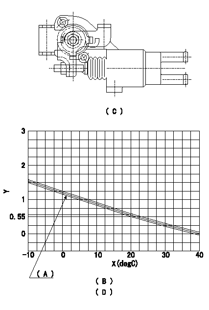
1. Adjustment of the advance angle of the timer
(1)Determine the timer advance angle from the graph in Fig. 2 (D).
(2)(1) Adjust with the screw so that the timer advance angle determined in the item (1) is obtained.
(C) Fig. 1
(D) Fig. 2
(A): TA+-0.1
(B): Timer stroke TA:
X:Temperature X
Y:Timer stroke TA (mm)
----------
----------
(B)=-10<=t(degC)<=20:TA=-0.0367t+1.284 (D)=20<=t(degC)<=40:TA=-0.0275t+1.1
----------
----------
(B)=-10<=t(degC)<=20:TA=-0.0367t+1.284 (D)=20<=t(degC)<=40:TA=-0.0275t+1.1
0000001901 V-FICD ADJUSTMENT

Adjustment of the V-FICD
1. Adjust the actuator rod to obtain L1mm.
2. Apply negative pressure of P1kPa {P2 mmHg} to the actuator and confirm that it moves through its full stroke.
A:Control lever idling position
----------
L=1+1mm P1=-53.3kPa P2=-400mmHg
----------
T1=3.4~4.9N-m{0.35~0.5kgf-m} T2=1.4~2.0N-m{0.14~0.2kgf-m} L=1+1mm
----------
L=1+1mm P1=-53.3kPa P2=-400mmHg
----------
T1=3.4~4.9N-m{0.35~0.5kgf-m} T2=1.4~2.0N-m{0.14~0.2kgf-m} L=1+1mm
Information:
Engine Model View
3408 Engine Shown
Turbochargers (1), Exhaust Outlet (2), Crankcase Breather (3), Lifting Eye (4), Flywheel (5), Magnetic Pickup (6), Electronic Control Module (ECM) (7), Oil Fill Tube (8), Thermostat (9), Primary Fuel Filter (10), Water Pump (11), Crankshaft Vibration Damper (12), Alternator (13), Oil Filters (14), Crankcase Drain Plug (15), Fuel Filters and Priming Pump (16).3408 Engine Description
Caterpillar 3408 electronically controlled Industrial Engines are 18 liter (1099 cu in), 137 mm (5.4 in) bore and 152.4 mm (6.0 in) stroke, four cycle, 8 cylinder, 65 degree vee diesel design. The engine is twin turbocharged with jacket water aftercooling and direct fuel injection. It is designed for petroleum and auxiliary industrial applications.The engine and components are designed for high power output. The reduced size and weight plus increased fuel economy provide maximum performance. Contact your Caterpillar dealer for information on power ratings.Larger diameter plungers and a higher injection rate camshaft are incorporated in the valve train/fuel system. The fuel lines are made of high strength steel and the ends of the lines have collared washers to increase reliability.The cooling system has a gear driven centrifugal water pump, two thermostats (one for each bank) which regulate engine coolant temperature, and an oil cooler. A customer supplied fan drive and cooling system (radiator) may be required for the industrial
Have questions with 104746-6231?
Group cross 104746-6231 ZEXEL
Isuzu
Isuzu
Isuzu
Isuzu
104746-6231
INJECTION-PUMP ASSEMBLY