Information injection-pump assembly
ZEXEL
104746-6191
1047466191

Rating:
Cross reference number
ZEXEL
104746-6191
1047466191
Zexel num
Bosch num
Firm num
Name
104746-6191
INJECTION-PUMP ASSEMBLY
Calibration Data:
Adjustment conditions
Test oil
1404 Test oil ISO4113orSAEJ967d
1404 Test oil ISO4113orSAEJ967d
Test oil temperature
degC
45
45
50
Nozzle
105780-0060
Bosch type code
NP-DN0SD1510
Nozzle holder
105780-2150
Opening pressure
MPa
13
13
13.3
Opening pressure
kgf/cm2
133
133
136
Injection pipe
157805-7320
Injection pipe
Inside diameter - outside diameter - length (mm) mm 2-6-450
Inside diameter - outside diameter - length (mm) mm 2-6-450
Joint assembly
157641-4720
Tube assembly
157641-4020
Transfer pump pressure
kPa
20
20
20
Transfer pump pressure
kgf/cm2
0.2
0.2
0.2
Direction of rotation (viewed from drive side)
Left L
Left L
Injection timing adjustment
Pump speed
r/min
1150
1150
1150
Average injection quantity
mm3/st.
51.4
50.9
51.9
Difference in delivery
mm3/st.
4
Basic
*
Oil temperature
degC
50
48
52
Injection timing adjustment_02
Pump speed
r/min
500
500
500
Average injection quantity
mm3/st.
30.3
26.8
33.8
Oil temperature
degC
48
46
50
Injection timing adjustment_03
Pump speed
r/min
750
750
750
Average injection quantity
mm3/st.
33.9
30.4
37.4
Oil temperature
degC
50
48
52
Injection timing adjustment_04
Pump speed
r/min
1150
1150
1150
Average injection quantity
mm3/st.
51.4
50.4
52.4
Difference in delivery
mm3/st.
4
Basic
*
Oil temperature
degC
50
48
52
Injection timing adjustment_05
Pump speed
r/min
2050
2050
2050
Average injection quantity
mm3/st.
58.3
53.8
62.8
Oil temperature
degC
52
50
54
Injection quantity adjustment
Pump speed
r/min
2350
2350
2350
Average injection quantity
mm3/st.
40.6
37.6
43.6
Difference in delivery
mm3/st.
8
Basic
*
Oil temperature
degC
52
50
54
Injection quantity adjustment_02
Pump speed
r/min
2700
2700
2700
Average injection quantity
mm3/st.
12
Oil temperature
degC
55
52
58
Injection quantity adjustment_03
Pump speed
r/min
2350
2350
2350
Average injection quantity
mm3/st.
40.6
37.6
43.6
Difference in delivery
mm3/st.
8
Basic
*
Oil temperature
degC
52
50
54
Governor adjustment
Pump speed
r/min
375
375
375
Average injection quantity
mm3/st.
8.4
6.4
10.4
Difference in delivery
mm3/st.
2
Basic
*
Oil temperature
degC
48
46
50
Governor adjustment_02
Pump speed
r/min
375
375
375
Average injection quantity
mm3/st.
8.4
6.4
10.4
Difference in delivery
mm3/st.
2
Basic
*
Oil temperature
degC
48
46
50
Timer adjustment
Pump speed
r/min
100
100
100
Average injection quantity
mm3/st.
60
60
100
Basic
*
Oil temperature
degC
48
46
50
Remarks
Full
Full
Timer adjustment_02
Pump speed
r/min
100
100
100
Average injection quantity
mm3/st.
60
60
100
Oil temperature
degC
48
46
50
Remarks
Full
Full
Speed control lever angle
Pump speed
r/min
375
375
375
Average injection quantity
mm3/st.
0
0
0
Oil temperature
degC
48
46
50
Remarks
Magnet OFF at idling position
Magnet OFF at idling position
0000000901
Pump speed
r/min
1400
1400
1400
Overflow quantity
cm3/min
370
240
500
Oil temperature
degC
50
48
52
Stop lever angle
Pump speed
r/min
1400
1400
1400
Pressure
kPa
412
392
432
Pressure
kgf/cm2
4.2
4
4.4
Basic
*
Oil temperature
degC
50
48
52
Stop lever angle_02
Pump speed
r/min
1400
1400
1400
Pressure
kPa
412
392
432
Pressure
kgf/cm2
4.2
4
4.4
Basic
*
Oil temperature
degC
50
48
52
0000001101
Pump speed
r/min
1400
1400
1400
Timer stroke
mm
3.3
2.9
3.7
Basic
*
Oil temperature
degC
50
48
52
_02
Pump speed
r/min
900
900
900
Timer stroke
mm
0.5
Oil temperature
degC
50
48
52
_03
Pump speed
r/min
1400
1400
1400
Timer stroke
mm
3.3
3.1
3.5
Basic
*
Oil temperature
degC
50
48
52
_04
Pump speed
r/min
1600
1600
1600
Timer stroke
mm
4.8
4.4
5.2
Oil temperature
degC
50
48
52
_05
Pump speed
r/min
1900
1900
1900
Timer stroke
mm
6.1
5.8
6.5
Oil temperature
degC
50
48
52
0000001201
Max. applied voltage
V
8
8
8
Test voltage
V
13
12
14
Timing setting
K dimension
mm
3.1
3
3.2
KF dimension
mm
5.5
5.4
5.6
MS dimension
mm
0.8
0.7
0.9
Pre-stroke
mm
0.45
0.43
0.47
Control lever angle alpha
deg.
18
14
22
Control lever angle beta
deg.
37
32
42
Test data Ex:
0000001801 V-FICD ADJUSTMENT

Adjustment of the W-CSD
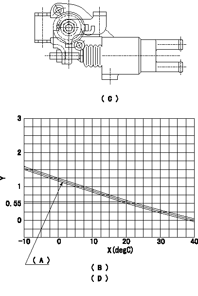
1. Adjustment of the advance angle of the timer
(1)Determine the timer advance angle from the graph in Fig. 2 (D).
(2)(1) Adjust with the screw so that the timer advance angle determined in the item (1) is obtained.
(C) Fig. 1
(D) Fig. 2
(A): TA+-0.1
(B): Timer stroke TA:
X:Temperature X
Y:Timer stroke TA (mm)
----------
----------
(B)=-10<=t(degC)<=20:TA=-0.0367t+1.284 (D)=20<=t(degC)<=40:TA=-0.0275t+1.1
----------
----------
(B)=-10<=t(degC)<=20:TA=-0.0367t+1.284 (D)=20<=t(degC)<=40:TA=-0.0275t+1.1
Information:
Bridge Adjustment
Intake and Exhaust Valve Mechanism
(1) Adjustment locknut, (2) Exhaust bridge, (3) Adjustment locknut, (4) Intake bridgeThe valve bridge should be checked and/or adjusted each time valve clearance is checked and/or adjusted. Valve and valve mechanism components do not always wear evenly which can allow the bridge to be out of adjustment.It is not necessary to remove the rocker arm shaft to adjust the valve bridges, but there must be clearance. Use the procedure that follows to make an adjustment to the bridge. Valves must be fully closed.1. Remove the valve covers from the engine.2. Lubricate the bridge dowel, bridge bore and the top pad of the bridge assembly with engine oil.3. While firmly pressing straight down on the bridge pad with a force of 1 to 10 lb (0.5 to 4.5 kg), turn the adjusting screw clockwise (CW) until contact is made with the valve stem.4. Turn the adjusting screw clockwise (CW) an additional 45° (1/8 turn) to straighten the dowel in the guide and compensate for slack in the threads.5. Hold the adjusting screw in this position and tighten the adjustment locknut to a torque of 18 5 lb ft (25 7 N m).6. Put engine oil at the point where the rocker arms make contact with the bridges.Valve Lash (Clearance) and Unit Injector Preload Adjustment
Valve clearance is measured between the rocker arm and the bridge for the valves.
Measure the valve lash with the engine stopped. To obtain an accurate measurement, allow at least 20 minutes for the valves to cool to engine cylinder head and block temperature.
When the valve lash (clearance) is checked, an adjustment is NOT necessary if the measurement is within the range given in the "Valve Clearance Check" chart shown. If the measurement is outside of the valve clearance check range shown, an adjustment is necessary. See the "Valve Clearance Setting" chart shown and make the setting to the nominal (desired) specifications in this chart. Adjust the valve clearance to within .003 in ( 0.08 mm) of the value given in the chart above.Rotate the engine crankshaft 360° in the normal crankshaft rotation direction before any adjustments are made. Operation of Caterpillar engines with improper valve adjustments will reduce engine efficiency. This reduced efficiency could result in excessive fuel usage and/or shortened engine component life.
Cylinder and Valve LocationTo make an adjustment to the valve clearance, turn the adjustment screw in the rocker arm. Valve clearance adjustments can be made by using the following procedure. The No. 1 piston must be at top center (TC) on the compression stroke. Follow the first three steps to find top center position for piston No. 1.
Locating Top Center for Piston No. 1
(1) Bolts (two - 6V5219), (2) Cover, (3) Flywheel Housing1. Remove two bolts (1) and remove cover (2) from the flywheel housing (3) to open the turning hole.2. Put one of the 6V5219 bolts in the timing hole located approximately 5 to 6 inches (127 to 152 mm) above the turning hole in
Have questions with 104746-6191?
Group cross 104746-6191 ZEXEL
Isuzu
104746-6191
INJECTION-PUMP ASSEMBLY