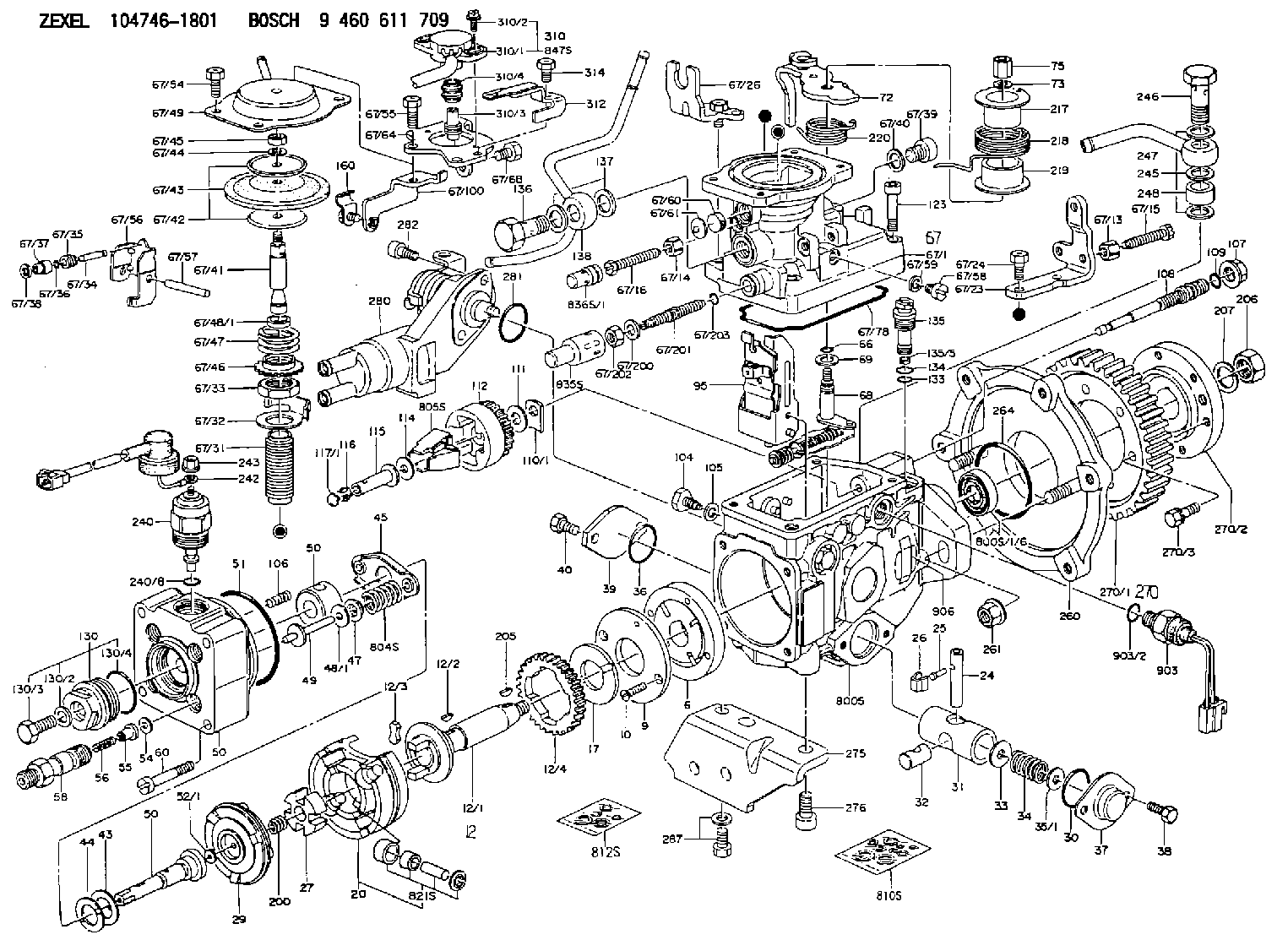
Information injection-pump assembly
BOSCH
9 460 611 709
9460611709
ZEXEL
104746-1801
1047461801
ISUZU
8971338471
8971338471

Rating:
Components :
| 0. | INJECTION-PUMP ASSEMBLY | 104746-1801 |
| 1. | _ | |
| 2. | FUEL INJECTION PUMP | 104646-1801 |
| 3. | NUMBER PLATE | 146967-1200 |
| 4. | _ | 146672-1720 |
| 5. | CAPSULE | |
| 6. | ADJUSTING DEVICE | |
| 7. | NOZZLE AND HOLDER ASSY | 105158-2311 |
| 8. | Nozzle and Holder | 8-97088-674-0 |
| 9. | Open Pre:MPa(Kqf/cm2) | 14.7{150} |
| 10. | NOZZLE-HOLDER | 105088-1130 |
| 11. | NOZZLE | 105007-1271 |
Scheme ###:
| 1/6. | [1] | 146601-0700 | PACKING RING |
| 6. | [1] | 146100-0120 | SUPPLY PUMP |
| 9. | [1] | 146103-0000 | COVER |
| 10. | [2] | 139104-0000 | FLAT-HEAD SCREW |
| 12. | [1] | 146200-0320 | DRIVE SHAFT |
| 12/1. | [1] | 146200-0300 | DRIVE SHAFT |
| 12/2. | [1] | 146201-0000 | WOODRUFF KEY |
| 12/3. | [2] | 146202-0100 | DAMPER |
| 12/4. | [1] | 146203-0000 | TOOTHED GEAR |
| 17. | [1] | 146204-0000 | PLAIN WASHER |
| 20. | [1] | 146210-5520 | ROLLER SET |
| 24. | [1] | 146303-0000 | BEARING PIN |
| 25. | [1] | 146304-0000 | BEARING PIN |
| 26. | [1] | 146305-0000 | CLAMPING BAND |
| 27. | [1] | 146205-0000 | SLOTTED WASHER |
| 29. | [1] | 146220-0020 | CAM PLATE |
| 30. | [1] | 146600-0800 | O-RING |
| 31. | [1] | 146300-0400 | PUMP PLUNGER |
| 32. | [1] | 146301-0000 | SLIDING PIECE |
| 33. | [1] | 146603-0700 | SHIM D17.5&7.5T0.60 |
| 34. | [1] | 146302-3400 | COMPRESSION SPRING |
| 34B. | [1] | 146302-3300 | COMPRESSION SPRING |
| 34C. | [1] | 146302-3500 | COMPRESSION SPRING |
| 34D. | [1] | 146302-3600 | COMPRESSION SPRING |
| 35/1. | [0] | 146603-0700 | SHIM D17.5&7.5T0.60 |
| 35/1. | [0] | 146603-0800 | SHIM D17.5&7.5T0.70 |
| 35/1. | [0] | 146603-0900 | SHIM D17.5&7.5T0.90 |
| 35/1. | [0] | 146603-1000 | SHIM D17.5&7.5T1.00 |
| 35/1. | [0] | 146603-1100 | SHIM D17.5&7.5T1.20 |
| 35/1. | [0] | 146603-3600 | SHIM D17.5&7.5T2.40 |
| 36. | [1] | 146600-0800 | O-RING |
| 37. | [1] | 146310-0700 | COVER |
| 38. | [2] | 146620-5000 | BLEEDER SCREW |
| 39. | [1] | 146310-0100 | COVER |
| 40. | [2] | 146620-5000 | BLEEDER SCREW |
| 43. | [1] | 146230-0000 | SHIM |
| 44. | [1] | 146230-0100 | PLAIN WASHER |
| 45. | [1] | 146231-0001 | SLOTTED WASHER |
| 47. | [2] | 146233-0000 | SLOTTED WASHER |
| 48/1. | [1] | 146603-0000 | SHIM D17.0&5.2T0.50 |
| 48/1. | [1] | 146603-0100 | SHIM D17.0&5.2T0.80 |
| 48/1. | [1] | 146603-0200 | SHIM D17.0&5.2T1.00 |
| 48/1. | [1] | 146603-0300 | SHIM D17.0&5.2T1.20 |
| 48/1. | [1] | 146603-0400 | SHIM D17.0&5.2T1.50 |
| 48/1. | [1] | 146603-0500 | SHIM D17.0&5.2T1.80 |
| 48/1. | [1] | 146603-0600 | SHIM D17.0&5.2T2.00 |
| 48/1. | [1] | 146690-1400 | SHIM D17&5.2T0.9 |
| 48/1. | [1] | 146690-1500 | SHIM D17&5.2T1.1 |
| 48/1. | [1] | 146690-1600 | SHIM D17&5.2T1.3 |
| 48/1. | [1] | 146690-1700 | SHIM D17&5.2T1.4 |
| 48/1. | [1] | 146690-1800 | SHIM D17&5.2T1.6 |
| 48/1. | [1] | 146690-1900 | SHIM D17&5.2T1.7 |
| 48/1. | [1] | 146690-5800 | SHIM |
| 48/1. | [1] | 146690-5900 | SHIM |
| 48/1. | [1] | 146690-6000 | SHIM |
| 48/1. | [1] | 146690-6100 | SHIM |
| 48/1. | [1] | 146690-6200 | SHIM |
| 48/1. | [1] | 146690-6300 | SHIM |
| 48/1. | [1] | 146690-6400 | SHIM |
| 48/1. | [1] | 146690-6500 | SHIM |
| 48/1. | [1] | 146690-6600 | SHIM |
| 48/1. | [1] | 146690-6700 | SHIM |
| 48/1. | [1] | 146690-6800 | SHIM |
| 48/1. | [1] | 146690-6900 | SHIM |
| 48/1. | [1] | 146690-7000 | SHIM |
| 48/1. | [1] | 146690-7100 | SHIM |
| 48/1. | [1] | 146690-7200 | SHIM |
| 48/1. | [1] | 146690-7300 | SHIM |
| 48/1. | [1] | 146690-7400 | SHIM |
| 48/1. | [1] | 146690-7500 | SHIM |
| 48/1. | [1] | 146690-7800 | SHIM |
| 49. | [2] | 146234-0020 | GUIDE PIN |
| 50. | [1] | 146403-3920 | HYDRAULIC HEAD |
| 50. | [1] | 146403-3920 | HYDRAULIC HEAD |
| 50. | [1] | 146403-3920 | HYDRAULIC HEAD |
| 51. | [1] | 146600-0000 | O-RING |
| 52/1. | [1] | 146420-0000 | SHIM D9.5&3.0T1.90 |
| 52/1. | [1] | 146420-0100 | SHIM D9.5&3.0T1.92 |
| 52/1. | [1] | 146420-0200 | SHIM D9.5&3.0T1.94 |
| 52/1. | [1] | 146420-0300 | SHIM D9.5&3.0T1.96 |
| 52/1. | [1] | 146420-0400 | SHIM D9.5&3.0T1.98 |
| 52/1. | [1] | 146420-0500 | SHIM D9.5&3.0T2.00 |
| 52/1. | [1] | 146420-0600 | SHIM D9.5&3.0T2.02 |
| 52/1. | [1] | 146420-0700 | SHIM D9.5&3.0T2.04 |
| 52/1. | [1] | 146420-0800 | SHIM D9.5&3.0T2.06 |
| 52/1. | [1] | 146420-0900 | SHIM D9.5&3.0T2.08 |
| 52/1. | [1] | 146420-1000 | SHIM D9.5&3.0T2.10 |
| 52/1. | [1] | 146420-1100 | SHIM D9.5&3.0T2.12 |
| 52/1. | [1] | 146420-1200 | SHIM D9.5&3.0T2.14 |
| 52/1. | [1] | 146420-1300 | SHIM D9.5&3.0T2.16 |
| 52/1. | [1] | 146420-1400 | SHIM D9.5&3.0T2.18 |
| 52/1. | [1] | 146420-1500 | SHIM D9.5&3.0T2.20 |
| 52/1. | [1] | 146420-1600 | SHIM D9.5&3.0T2.22 |
| 52/1. | [1] | 146420-1700 | SHIM D9.5&3.0T2.24 |
| 52/1. | [1] | 146420-1800 | SHIM D9.5&3.0T2.26 |
| 52/1. | [1] | 146420-1900 | SHIM D9.5&3.0T2.28 |
| 52/1. | [1] | 146420-2000 | SHIM D9.5&3.0T2.30 |
| 52/1. | [1] | 146420-2100 | SHIM D9.5&3.0T2.32 |
| 52/1. | [1] | 146420-2200 | SHIM D9.5&3.0T2.34 |
| 52/1. | [1] | 146420-2300 | SHIM D9.5&3.0T2.36 |
| 52/1. | [1] | 146420-2400 | SHIM D9.5&3.0T2.38 |
| 52/1. | [1] | 146420-2500 | SHIM D9.5&3.0T2.40 |
| 52/1. | [1] | 146420-2600 | SHIM D9.5&3.0T2.42 |
| 52/1. | [1] | 146420-2700 | SHIM D9.5&3.0T2.44 |
| 52/1. | [1] | 146420-2800 | SHIM D9.5&3.0T2.46 |
| 52/1. | [1] | 146420-2900 | SHIM D9.5&3.0T2.48 |
| 52/1. | [1] | 146420-3000 | SHIM D9.5&3.0T2.50 |
| 52/1. | [1] | 146420-3100 | SHIM D9.5&3.0T2.52 |
| 52/1. | [1] | 146420-3200 | SHIM D9.5&3.0T2.54 |
| 52/1. | [1] | 146420-3300 | SHIM D9.5&3.0T2.56 |
| 52/1. | [1] | 146420-3400 | SHIM D9.5&3.0T2.58 |
| 52/1. | [1] | 146420-3500 | SHIM D9.5&3.0T2.60 |
| 52/1. | [1] | 146420-3600 | SHIM D9.5&3.0T2.62 |
| 52/1. | [1] | 146420-3700 | SHIM D9.5&3.0T2.64 |
| 52/1. | [1] | 146420-3800 | SHIM D9.5&3.0T2.66 |
| 52/1. | [1] | 146420-3900 | SHIM D9.5&3.0T2.68 |
| 52/1. | [1] | 146420-4000 | SHIM D9.5&3.0T2.70 |
| 52/1. | [1] | 146420-4100 | SHIM D9.5&3.0T2.72 |
| 52/1. | [1] | 146420-4200 | SHIM D9.5&3.0T2.74 |
| 52/1. | [1] | 146420-4300 | SHIM D9.5&3.0T2.76 |
| 52/1. | [1] | 146420-4400 | SHIM D9.5&3.0T2.78 |
| 52/1. | [1] | 146420-4500 | SHIM D9.5&3.0T2.80 |
| 52/1. | [1] | 146420-4600 | SHIM D9.5&3.0T2.82 |
| 52/1. | [1] | 146420-4700 | SHIM D9.5&3.0T2.84 |
| 52/1. | [1] | 146420-4800 | SHIM D9.5&3.0T2.86 |
| 52/1. | [1] | 146420-4900 | SHIM D9.5&3.0T2.88 |
| 52/1. | [1] | 146420-5000 | SHIM D9.5&3.0T2.90 |
| 52/1. | [1] | 146420-5100 | SHIM D9.5&3.0T1.74 |
| 52/1. | [1] | 146420-5200 | SHIM D9.5&3.0T1.76 |
| 52/1. | [1] | 146420-5300 | SHIM D9.5&3.0T1.78 |
| 52/1. | [1] | 146420-5400 | SHIM D9.5&3.0T1.80 |
| 52/1. | [1] | 146420-5500 | SHIM D9.5&3.0T1.82 |
| 52/1. | [1] | 146420-5600 | SHIM D9.5&3.0T1.84 |
| 52/1. | [1] | 146420-5700 | SHIM D9.5&3.0T1.86 |
| 52/1. | [1] | 146420-5800 | SHIM D9.5&3.0T1.88 |
| 54. | [4] | 146433-0100 | GASKET D12&6.4T1.00 |
| 55. | [4] | 146430-0320 | DELIVERY-VALVE ASSEMBLY |
| 56. | [4] | 146432-0000 | COMPRESSION SPRING |
| 58. | [4] | 146440-0120 | FITTING |
| 60. | [4] | 139106-0100 | FLAT-HEAD SCREW |
| 66. | [1] | 146600-0100 | O-RING |
| 67. | [1] | 146760-1820 | MANIFOLD-PRESSURE COMP. |
| 67/1. | [1] | 146805-7420 | GOVERNOR COVER |
| 67/13. | [1] | 013020-6040 | UNION NUT M6P1H5 |
| 67/14. | [1] | 146621-1700 | UNION NUT |
| 67/15. | [1] | 146526-1800 | BLEEDER SCREW |
| 67/16. | [1] | 146526-3000 | BLEEDER SCREW |
| 67/23. | [1] | 146928-5500 | BRACKET |
| 67/24. | [2] | 139006-4500 | BLEEDER SCREW |
| 67/26. | [1] | 146930-3520 | BRACKET |
| 67/31. | [1] | 146710-0800 | BUSHING |
| 67/32. | [1] | 146711-0000 | PLATE |
| 67/33. | [1] | 139218-0400 | UNION NUT |
| 67/34. | [1] | 146712-0700 | BEARING PIN |
| 67/35. | [1] | 146621-0300 | UNION NUT |
| 67/36. | [1] | 146600-1400 | O-RING |
| 67/37. | [1] | 146710-0100 | BUSHING |
| 67/38. | [1] | 139506-0200 | GASKET D8.9&6.8T1.00 |
| 67/39. | [1] | 146620-0300 | CAPSULE |
| 67/40. | [1] | 026512-1540 | GASKET D15.4&12.2T1.50 |
| 67/41. | [1] | 146713-4100 | ADJUSTING PIN |
| 67/42. | [2] | 146714-0000 | PLATE |
| 67/43. | [1] | 146715-0000 | DIAPHRAGM |
| 67/44. | [1] | 139306-0100 | LOCKING WASHER |
| 67/45. | [1] | 013030-6040 | UNION NUT M6P1H3.6 |
| 67/46. | [1] | 146716-0000 | UNION NUT |
| 67/47. | [1] | 146717-0300 | COILED SPRING |
| 67/48/1. | [1] | 146720-0000 | SPACER BUSHING L3.7 |
| 67/48/1. | [1] | 146720-0100 | SPACER BUSHING L3.9 |
| 67/48/1. | [1] | 146720-0200 | SPACER BUSHING L4.1 |
| 67/48/1. | [1] | 146720-0300 | SPACER BUSHING L4.3 |
| 67/48/1. | [1] | 146720-0400 | SPACER BUSHING L4.5 |
| 67/48/1. | [1] | 146720-0500 | SPACER BUSHING L4.7 |
| 67/48/1. | [1] | 146720-0600 | SPACER BUSHING L4.9 |
| 67/48/1. | [1] | 146720-0700 | SPACER BUSHING L5.1 |
| 67/48/1. | [1] | 146720-0800 | SPACER BUSHING L5.3 |
| 67/48/1. | [1] | 146720-0900 | SPACER BUSHING L2.7 |
| 67/48/1. | [1] | 146720-1000 | SPACER BUSHING L2.9 |
| 67/48/1. | [1] | 146720-1100 | SPACER BUSHING L3.1 |
| 67/48/1. | [1] | 146720-1200 | SPACER BUSHING L3.3 |
| 67/48/1. | [1] | 146720-1200 | SPACER BUSHING L3.3 |
| 67/48/1. | [1] | 146720-1300 | SPACER BUSHING L3.5 |
| 67/48/1. | [1] | 146720-1400 | SPACER BUSHING L2.8 |
| 67/48/1. | [1] | 146720-1500 | SPACER BUSHING L3.0 |
| 67/48/1. | [1] | 146720-1600 | SPACER BUSHING L3.2 |
| 67/48/1. | [1] | 146720-1700 | SPACER BUSHING L3.4 |
| 67/48/1. | [1] | 146720-1800 | SPACER BUSHING L3.6 |
| 67/48/1. | [1] | 146720-1900 | SPACER BUSHING L3.8 |
| 67/48/1. | [1] | 146720-2000 | SPACER BUSHING L4.0 |
| 67/48/1. | [1] | 146720-2100 | SPACER BUSHING L4.2 |
| 67/48/1. | [1] | 146720-2200 | SPACER BUSHING L4.4 |
| 67/48/1. | [1] | 146720-2300 | SPACER BUSHING L4.6 |
| 67/48/1. | [1] | 146720-2400 | SPACER BUSHING L4.8 |
| 67/48/1. | [1] | 146720-2500 | SPACER BUSHING L5.0 |
| 67/48/1. | [1] | 146720-2600 | SPACER BUSHING L5.2 |
| 67/48/1. | [1] | 146720-2700 | SPACER BUSHING L5.4 |
| 67/48/1. | [1] | 146720-2800 | SPACER BUSHING L5.5 |
| 67/48/1. | [1] | 146720-2900 | SPACER BUSHING L5.6 |
| 67/48/1. | [1] | 146720-4500 | SPACER BUSHING L1.8 |
| 67/48/1. | [1] | 146720-4600 | SPACER BUSHING L1.9 |
| 67/48/1. | [1] | 146720-4700 | SPACER BUSHING L2.0 |
| 67/48/1. | [1] | 146720-4800 | SPACER BUSHING L2.1 |
| 67/48/1. | [1] | 146720-4900 | SPACER BUSHING L2.2 |
| 67/48/1. | [1] | 146720-5000 | SPACER BUSHING L2.3 |
| 67/48/1. | [1] | 146720-5100 | SPACER BUSHING L2.4 |
| 67/48/1. | [1] | 146720-5200 | SPACER BUSHING L2.5 |
| 67/48/1. | [1] | 146720-5300 | SPACER BUSHING L2.6 |
| 67/48/1. | [1] | 146725-2500 | SPACER BUSHING L5.7 |
| 67/48/1. | [1] | 146725-2600 | SPACER BUSHING L5.8 |
| 67/48/1. | [1] | 146725-2700 | SPACER BUSHING L5.9 |
| 67/48/1. | [1] | 146725-2800 | SPACER BUSHING L6.0 |
| 67/48/1. | [1] | 146725-2900 | SPACER BUSHING L6.1 |
| 67/48/1. | [1] | 146725-3000 | SPACER BUSHING L6.2 |
| 67/48/1. | [1] | 146725-3100 | SPACER BUSHING L6.3 |
| 67/48/1. | [1] | 146725-3200 | SPACER BUSHING L6.4 |
| 67/48/1. | [1] | 146725-3300 | SPACER BUSHING L6.5 |
| 67/48/1. | [1] | 146725-3400 | SPACER BUSHING L6.6 |
| 67/48/1. | [1] | 146725-3500 | SPACER BUSHING L6.7 |
| 67/48/1. | [1] | 146725-3600 | SPACER BUSHING L6.8 |
| 67/48/1. | [1] | 146725-3700 | SPACER BUSHING L6.9 |
| 67/48/1. | [1] | 146725-3800 | SPACER BUSHING L7.0 |
| 67/48/1. | [1] | 146725-3900 | SPACER BUSHING L7.1 |
| 67/48/1. | [1] | 146725-4000 | SPACER BUSHING L7.2 |
| 67/48/1. | [1] | 146725-4100 | SPACER BUSHING L7.3 |
| 67/48/1. | [1] | 146725-4200 | SPACER BUSHING L7.4 |
| 67/48/1. | [1] | 146725-4300 | SPACER BUSHING L7.5 |
| 67/49. | [1] | 146721-3020 | COVER |
| 67/54. | [3] | 139006-4500 | BLEEDER SCREW |
| 67/55. | [1] | 139006-4700 | BLEEDER SCREW |
| 67/56. | [1] | 146723-0920 | CONTROL LEVER |
| 67/57. | [1] | 146712-0100 | BEARING PIN |
| 67/58. | [2] | 146620-0600 | CAPSULE |
| 67/59. | [2] | 026506-1040 | GASKET D9.9&6.2T1 |
| 67/60. | [1] | 146724-0300 | ELEMENT |
| 67/61. | [1] | 146724-0600 | CAPSULE |
| 67/64. | [1] | 146933-4400 | BRACKET |
| 67/68. | [1] | 139006-4400 | BLEEDER SCREW |
| 67/78. | [1] | 146600-4400 | SEAL RING |
| 67/100. | [1] | 146928-5700 | BRACKET |
| 67/200. | [1] | 139308-0300 | PLAIN WASHER |
| 67/201. | [1] | 146545-3400 | THREADED PIN L53.00 |
| 67/201B. | [1] | 146545-3500 | THREADED PIN L55.00 |
| 67/201C. | [1] | 146545-3600 | THREADED PIN L57.00 |
| 67/202. | [1] | 139208-0900 | UNION NUT |
| 67/203. | [1] | 146600-1200 | O-RING |
| 68. | [1] | 146514-3521 | CONTROL SHAFT |
| 69. | [1] | 139310-0200 | PLAIN WASHER |
| 72. | [1] | 146539-5701 | CONTROL LEVER |
| 72B. | [1] | 146539-5801 | CONTROL LEVER |
| 73. | [1] | 014110-6440 | LOCKING WASHER |
| 75. | [1] | 013020-6040 | UNION NUT M6P1H5 |
| 95. | [1] | 146861-2320 | FULCRUM LEVER |
| 104. | [2] | 146568-0000 | SLOTTED SPRING PIN |
| 105. | [2] | 026508-1140 | GASKET D11.4&8.2T1 |
| 106. | [2] | 146588-0500 | COILED SPRING |
| 107. | [1] | 146569-0300 | UNION NUT |
| 108. | [1] | 146570-0420 | GOVERNOR SHAFT |
| 109. | [1] | 146600-0400 | O-RING |
| 110/1. | [1] | 146571-0000 | SHIM D20.2&8.3T1.05 |
| 110/1. | [1] | 146571-0100 | SHIM D20.2&8.3T1.25 |
| 110/1. | [1] | 146571-0200 | SHIM D20.2&8.3T1.45 |
| 110/1. | [1] | 146571-0300 | SHIM D20.2&8.3T1.65 |
| 110/1. | [1] | 146571-0400 | SHIM D20.2&8.3T1.85 |
| 110/1. | [1] | 146571-0500 | SHIM D20.2&8.3T1.15 |
| 110/1. | [1] | 146571-0600 | SHIM D20.2&8.3T1.35 |
| 110/1. | [1] | 146571-0700 | SHIM D20.2&8.3T1.55 |
| 110/1. | [1] | 146571-0800 | SHIM D20.2&8.3T1.75 |
| 111. | [1] | 146602-0600 | PLAIN WASHER D20&8.4T1.40 |
| 112. | [1] | 146572-0020 | FLYWEIGHT ASSEMBLY |
| 114. | [1] | 146602-0500 | PLAIN WASHER D17&6.4T1.60 |
| 115. | [1] | 146875-8000 | SLIDING SLEEVE |
| 116. | [1] | 146576-0200 | CAP |
| 117/1. | [1] | 146577-1800 | PLUG L2.10 |
| 117/1. | [1] | 146577-1900 | PLUG L2.30 |
| 117/1. | [1] | 146577-2000 | PLUG L2.50 |
| 117/1. | [1] | 146577-2100 | PLUG L2.70 |
| 117/1. | [1] | 146577-2200 | PLUG L2.90 |
| 117/1. | [1] | 146577-2300 | PLUG L3.10 |
| 117/1. | [1] | 146577-2400 | PLUG L3.30 |
| 117/1. | [1] | 146577-2500 | PLUG L3.50 |
| 117/1. | [1] | 146577-2600 | PLUG L3.70 |
| 117/1. | [1] | 146577-2700 | PLUG L3.90 |
| 117/1. | [1] | 146577-2800 | PLUG L4.10 |
| 117/1. | [1] | 146577-2900 | PLUG L4.30 |
| 117/1. | [1] | 146577-3000 | PLUG L4.50 |
| 117/1. | [1] | 146577-3100 | PLUG L4.70 |
| 117/1. | [1] | 146577-3200 | PLUG L4.90 |
| 117/1. | [1] | 146577-3300 | PLUG L5.10 |
| 117/1. | [1] | 146577-6700 | PLUG L2.2 |
| 117/1. | [1] | 146577-6800 | PLUG L2.4 |
| 117/1. | [1] | 146577-6900 | PLUG L2.6 |
| 117/1. | [1] | 146577-7000 | PLUG L2.8 |
| 117/1. | [1] | 146577-7100 | PLUG L3.0 |
| 117/1. | [1] | 146577-7200 | PLUG L3.2 |
| 117/1. | [1] | 146577-7300 | PLUG L3.4 |
| 117/1. | [1] | 146577-7400 | PLUG L3.6 |
| 117/1. | [1] | 146577-7500 | PLUG L3.8 |
| 117/1. | [1] | 146577-7600 | PLUG L4.0 |
| 117/1. | [1] | 146577-7700 | PLUG L4.2 |
| 117/1. | [1] | 146577-7800 | PLUG L4.4 |
| 117/1. | [1] | 146577-7900 | PLUG L4.6 |
| 117/1. | [1] | 146577-8000 | PLUG L4.8 |
| 117/1. | [1] | 146577-8100 | PLUG L5.0 |
| 117/1. | [1] | 146877-0000 | PLUG L5.2 |
| 117/1. | [1] | 146877-0100 | PLUG L5.3 |
| 117/1. | [1] | 146877-0200 | PLUG L5.4 |
| 117/1. | [1] | 146877-0300 | PLUG L5.5 |
| 117/1. | [1] | 146877-4700 | PLUG |
| 117/1. | [1] | 146877-4800 | PLUG |
| 117/1. | [1] | 146877-4900 | PLUG |
| 117/1. | [1] | 146877-5000 | PLUG |
| 123. | [4] | 146620-0500 | HEX-SOCKET-HEAD CAP SCREW |
| 130. | [1] | 146421-0020 | CAPSULE |
| 130/2. | [1] | 026508-1140 | GASKET D11.4&8.2T1 |
| 130/3. | [1] | 146422-0000 | BLEEDER SCREW |
| 130/4. | [1] | 146600-0500 | O-RING |
| 133. | [1] | 146600-0600 | O-RING |
| 134. | [1] | 146600-0700 | O-RING |
| 135. | [1] | 146110-0920 | CONTROL VALVE |
| 135/5. | [1] | 146114-0000 | SPRING WASHER |
| 136. | [1] | 146120-1520 | OVER FLOW VALVE |
| 137. | [2] | 139512-0500 | GASKET |
| 138. | [1] | 146665-5620 | INLET UNION |
| 160. | [1] | 146625-8020 | PLATE |
| 200. | [1] | 146206-0100 | COILED SPRING |
| 205. | [1] | 029470-4030 | WOODRUFF KEY |
| 206. | [1] | 013121-4140 | UNION NUT M14P1.5H11 |
| 207. | [1] | 029321-4050 | LOCKING WASHER |
| 217. | [1] | 146541-2900 | SLOTTED WASHER |
| 218. | [1] | 146592-4300 | COILED SPRING |
| 219. | [1] | 146541-3000 | BUSHING |
| 220. | [1] | 146592-4400 | COILED SPRING |
| 240. | [1] | 146650-1220 | PULLING ELECTROMAGNET |
| 240/8. | [1] | 146600-1700 | O-RING |
| 242. | [1] | 146658-7320 | WIRE |
| 243. | [1] | 146621-1000 | UNION NUT |
| 245. | [2] | 139512-0500 | GASKET |
| 246. | [1] | 027412-2440 | EYE BOLT |
| 247. | [1] | 146609-4620 | INLET UNION |
| 260. | [1] | 146611-0720 | BRACKET |
| 261. | [2] | 146621-4700 | UNION NUT |
| 264. | [1] | 016500-5010 | O-RING |
| 270. | [1] | 146615-3820 | TOOTHED GEAR |
| 270/1. | [1] | 146615-2600 | TOOTHED GEAR |
| 270/2. | [1] | 146615-3700 | COUPLING PLATE |
| 270/3. | [6] | 020006-1870 | BLEEDER SCREW M6P1L18 7T |
| 275. | [1] | 146612-6220 | BRACKET |
| 276. | [2] | 010210-1640 | HEX-SOCKET-HEAD CAP SCREW |
| 280. | [1] | 146361-3820 | START ADVANCE ASSY |
| 281. | [1] | 146600-0800 | O-RING |
| 282. | [1] | 010206-1240 | HEX-SOCKET-HEAD CAP SCREW M6P1L12 |
| 287. | [1] | 139006-6600 | BLEEDER SCREW |
| 310. | [1] | 146683-4721 | POTENTCIOMETER |
| 310/1. | [1] | 146684-5500 | POTENTCIOMETER |
| 310/2. | [2] | 139104-0400 | FLAT-HEAD SCREW |
| 310/3. | [1] | 146648-9200 | JOINT CONNECTION |
| 310/3B. | [1] | 146648-9300 | JOINT CONNECTION |
| 310/3C. | [1] | 146648-9400 | JOINT CONNECTION |
| 310/3D. | [1] | 146648-9500 | JOINT CONNECTION |
| 310/3E. | [1] | 146648-9600 | JOINT CONNECTION |
| 310/3F. | [1] | 146648-9700 | JOINT CONNECTION |
| 310/3G. | [1] | 146648-9800 | JOINT CONNECTION |
| 310/3H. | [1] | 146648-9900 | JOINT CONNECTION |
| 310/3I. | [1] | 146649-0000 | JOINT CONNECTION |
| 310/3J. | [1] | 146649-0100 | JOINT CONNECTION |
| 310/3K. | [1] | 146649-0200 | JOINT CONNECTION |
| 310/3L. | [1] | 146649-0300 | JOINT CONNECTION |
| 310/4. | [1] | 146661-0601 | BOOT |
| 312. | [1] | 146933-4520 | PLATE |
| 314. | [1] | 139006-4400 | BLEEDER SCREW |
| 800S. | [1] | 146018-6620 | PUMP HOUSING |
| 800S/1/6. | [1] | 146601-0700 | PACKING RING |
| 800S/1/6. | [1] | 146601-0700 | PACKING RING |
| 804S. | [1] | 146232-0320 | COMPRESSION SPRING |
| 805S. | [1] | 146574-0120 | PARTS SET |
| 810S. | [1] | 146600-1120 | REPAIR SET |
| 812S. | [1] | 146600-1920 | PARTS SET |
| 821S. | [1] | 146210-5720 | ROLLER SET |
| 835S. | [1] | 146598-1000 | CAP |
| 836S/1. | [1] | 146598-0600 | CAP L18 |
| 836S/1. | [1] | 146598-0700 | CAP L21 |
| 836S/1. | [1] | 146598-0800 | CAP L24 |
| 836S/1. | [1] | 146598-0900 | CAP L27 |
| 847S. | [1] | 146683-4710 | POTENTCIOMETER |
| 903. | [1] | 146672-1720 | PULSE GENERATOR |
| 903/2. | [1] | 146600-1300 | O-RING &13W1.9 |
| 906. | [1] | 146967-1200 | NAMEPLATE |
Include in #2:
104746-1801
as INJECTION-PUMP ASSEMBLY
Cross reference number
BOSCH
9 460 611 709
9460611709
ZEXEL
104746-1801
1047461801
ISUZU
8971338471
8971338471
Zexel num
Bosch num
Firm num
Name
104746-1801
9 460 611 709
8971338471 ISUZU
INJECTION-PUMP ASSEMBLY
4JG2-TC K
4JG2-TC K
Calibration Data:
Adjustment conditions
Test oil
1404 Test oil ISO4113orSAEJ967d
1404 Test oil ISO4113orSAEJ967d
Test oil temperature
degC
45
45
50
Nozzle
105780-0060
Bosch type code
NP-DN0SD1510
Nozzle holder
105780-2150
Opening pressure
MPa
13
13
13.3
Opening pressure
kgf/cm2
133
133
136
Injection pipe
157805-7320
Injection pipe
Inside diameter - outside diameter - length (mm) mm 2-6-450
Inside diameter - outside diameter - length (mm) mm 2-6-450
Joint assembly
157641-4720
Tube assembly
157641-4020
Transfer pump pressure
kPa
20
20
20
Transfer pump pressure
kgf/cm2
0.2
0.2
0.2
Direction of rotation (viewed from drive side)
Left L
Left L
Injection timing adjustment
Pump speed
r/min
600
600
600
Boost pressure
kPa
30
28.7
31.3
Boost pressure
kgf/cm2
0.31
0.296
0.324
Boost pressure
mmHg
225
215
235
Average injection quantity
mm3/st.
73
72.5
73.5
Difference in delivery
mm3/st.
4.5
Basic
*
Oil temperature
degC
50
48
52
Remarks
CBS
CBS
Injection timing adjustment_02
Pump speed
r/min
1000
1000
1000
Boost pressure
kPa
73.3
72
74.6
Boost pressure
kgf/cm2
0.75
0.736
0.764
Boost pressure
mmHg
550
540
560
Average injection quantity
mm3/st.
74.9
74.4
75.4
Difference in delivery
mm3/st.
3.5
Basic
*
Oil temperature
degC
50
48
52
Remarks
Full
Full
Injection timing adjustment_03
Pump speed
r/min
600
600
600
Boost pressure
kPa
30
28.7
31.3
Boost pressure
kgf/cm2
0.31
0.296
0.324
Boost pressure
mmHg
225
215
235
Average injection quantity
mm3/st.
73
72
74
Difference in delivery
mm3/st.
4.5
Basic
*
Oil temperature
degC
50
48
52
Remarks
CBS
CBS
Injection timing adjustment_04
Pump speed
r/min
750
750
750
Boost pressure
kPa
0
0
0
Boost pressure
kgf/cm2
0
0
0
Boost pressure
mmHg
0
0
0
Average injection quantity
mm3/st.
59.6
59.6
59.6
Oil temperature
degC
50
48
52
Injection timing adjustment_05
Pump speed
r/min
1000
1000
1000
Boost pressure
kPa
73.3
72
74.6
Boost pressure
kgf/cm2
0.75
0.736
0.764
Boost pressure
mmHg
550
540
560
Average injection quantity
mm3/st.
74.9
73.9
75.9
Difference in delivery
mm3/st.
3.5
Basic
*
Oil temperature
degC
50
48
52
Remarks
Full
Full
Injection timing adjustment_06
Pump speed
r/min
1000
1000
1000
Boost pressure
kPa
0
0
0
Boost pressure
kgf/cm2
0
0
0
Boost pressure
mmHg
0
0
0
Average injection quantity
mm3/st.
58.2
58.2
58.2
Oil temperature
degC
50
48
52
Injection timing adjustment_07
Pump speed
r/min
1800
1800
1800
Boost pressure
kPa
73.3
72
74.6
Boost pressure
kgf/cm2
0.75
0.736
0.764
Boost pressure
mmHg
550
540
560
Average injection quantity
mm3/st.
72.6
69.1
76.1
Oil temperature
degC
50
48
52
Injection quantity adjustment
Pump speed
r/min
2300
2300
2300
Boost pressure
kPa
73.3
72
74.6
Boost pressure
kgf/cm2
0.75
0.736
0.764
Boost pressure
mmHg
550
540
560
Average injection quantity
mm3/st.
34.6
31.6
37.6
Difference in delivery
mm3/st.
5.5
Basic
*
Oil temperature
degC
52
50
54
Injection quantity adjustment_02
Pump speed
r/min
2550
2550
2550
Boost pressure
kPa
73.3
72
74.6
Boost pressure
kgf/cm2
0.75
0.736
0.764
Boost pressure
mmHg
550
540
560
Average injection quantity
mm3/st.
5
Oil temperature
degC
55
52
58
Injection quantity adjustment_03
Pump speed
r/min
2300
2300
2300
Boost pressure
kPa
73.3
72
74.6
Boost pressure
kgf/cm2
0.75
0.736
0.764
Boost pressure
mmHg
550
540
560
Average injection quantity
mm3/st.
34.6
31.6
37.6
Difference in delivery
mm3/st.
5.5
Basic
*
Oil temperature
degC
52
50
54
Governor adjustment
Pump speed
r/min
360
360
360
Boost pressure
kPa
0
0
0
Boost pressure
kgf/cm2
0
0
0
Boost pressure
mmHg
0
0
0
Average injection quantity
mm3/st.
15.8
13.8
17.8
Difference in delivery
mm3/st.
2
Basic
*
Oil temperature
degC
48
46
50
Governor adjustment_02
Pump speed
r/min
360
360
360
Boost pressure
kPa
0
0
0
Boost pressure
kgf/cm2
0
0
0
Boost pressure
mmHg
0
0
0
Average injection quantity
mm3/st.
15.8
13.8
17.8
Difference in delivery
mm3/st.
2
Basic
*
Oil temperature
degC
48
46
50
Timer adjustment
Pump speed
r/min
100
100
100
Boost pressure
kPa
0
0
0
Boost pressure
kgf/cm2
0
0
0
Boost pressure
mmHg
0
0
0
Average injection quantity
mm3/st.
75
65
85
Basic
*
Oil temperature
degC
48
46
50
Remarks
IDLE
IDLE
Timer adjustment_02
Pump speed
r/min
100
100
100
Boost pressure
kPa
0
0
0
Boost pressure
kgf/cm2
0
0
0
Boost pressure
mmHg
0
0
0
Average injection quantity
mm3/st.
75
65
85
Oil temperature
degC
48
46
50
Speed control lever angle
Pump speed
r/min
360
360
360
Boost pressure
kPa
0
0
0
Boost pressure
kgf/cm2
0
0
0
Boost pressure
mmHg
0
0
0
Average injection quantity
mm3/st.
0
0
0
Oil temperature
degC
48
46
50
Remarks
Magnet OFF at idling position
Magnet OFF at idling position
0000000901
Pump speed
r/min
1250
1250
1250
Boost pressure
kPa
73.3
72
74.6
Boost pressure
kgf/cm2
0.75
0.736
0.764
Boost pressure
mmHg
550
540
560
Overflow quantity
cm3/min
650
520
780
Oil temperature
degC
50
48
52
Stop lever angle
Pump speed
r/min
1250
1250
1250
Boost pressure
kPa
73.3
72
74.6
Boost pressure
kgf/cm2
0.75
0.736
0.764
Boost pressure
mmHg
550
540
560
Pressure
kPa
490
470
510
Pressure
kgf/cm2
5
4.8
5.2
Basic
*
Oil temperature
degC
50
48
52
Stop lever angle_02
Pump speed
r/min
1250
1250
1250
Boost pressure
kPa
73.3
72
74.6
Boost pressure
kgf/cm2
0.75
0.736
0.764
Boost pressure
mmHg
550
540
560
Pressure
kPa
490
470
510
Pressure
kgf/cm2
5
4.8
5.2
Basic
*
Oil temperature
degC
50
48
52
0000001101
Pump speed
r/min
1250
1250
1250
Boost pressure
kPa
73.3
72
74.6
Boost pressure
kgf/cm2
0.75
0.736
0.764
Boost pressure
mmHg
550
540
560
Timer stroke
mm
3.3
3.1
3.5
Basic
*
Oil temperature
degC
50
48
52
_02
Pump speed
r/min
675
675
675
Boost pressure
kPa
73.3
72
74.6
Boost pressure
kgf/cm2
0.75
0.736
0.764
Boost pressure
mmHg
550
540
560
Timer stroke
mm
1
0.9
1.1
Oil temperature
degC
50
48
52
_03
Pump speed
r/min
1250
1250
1250
Boost pressure
kPa
73.3
72
74.6
Boost pressure
kgf/cm2
0.75
0.736
0.764
Boost pressure
mmHg
550
540
560
Timer stroke
mm
3.3
3.1
3.5
Basic
*
Oil temperature
degC
50
48
52
_04
Pump speed
r/min
1500
1500
1500
Boost pressure
kPa
73.3
72
74.6
Boost pressure
kgf/cm2
0.75
0.736
0.764
Boost pressure
mmHg
550
540
560
Timer stroke
mm
4.5
4.4
4.6
Oil temperature
degC
50
48
52
_05
Pump speed
r/min
2000
2000
2000
Boost pressure
kPa
73.3
72
74.6
Boost pressure
kgf/cm2
0.75
0.736
0.764
Boost pressure
mmHg
550
540
560
Timer stroke
mm
6.6
6.3
7
Oil temperature
degC
50
48
52
0000001201
Max. applied voltage
V
8
8
8
Test voltage
V
13
12
14
0000001401
Pump speed
r/min
1250
1250
1250
Boost pressure
kPa
73.3
72
74.6
Boost pressure
kgf/cm2
0.75
0.736
0.764
Boost pressure
mmHg
550
540
560
Average injection quantity
mm3/st.
55.4
54.4
56.4
Timer stroke TA
mm
2.4
2.2
2.6
Timer stroke variation dT
mm
0.9
0.9
0.9
Basic
*
Oil temperature
degC
50
48
52
_02
Pump speed
r/min
1250
1250
1250
Boost pressure
kPa
73.3
72
74.6
Boost pressure
kgf/cm2
0.75
0.736
0.764
Boost pressure
mmHg
550
540
560
Average injection quantity
mm3/st.
55.4
53.9
56.9
Timer stroke TA
mm
2.4
2
2.8
Basic
*
Oil temperature
degC
50
48
52
_03
Pump speed
r/min
1250
1250
1250
Boost pressure
kPa
73.3
72
74.6
Boost pressure
kgf/cm2
0.75
0.736
0.764
Boost pressure
mmHg
550
540
560
Average injection quantity
mm3/st.
38.8
37.3
40.3
Timer stroke TA
mm
1.4
0.8
2
Oil temperature
degC
50
48
52
Timing setting
K dimension
mm
3.3
3.2
3.4
KF dimension
mm
5.8
5.7
5.9
MS dimension
mm
0.7
0.6
0.8
BCS stroke
mm
3.3
3.1
3.5
Control lever angle alpha
deg.
24
20
28
Control lever angle beta
deg.
45
40
50
Test data Ex:
0000001801 POTENTIOMETER ADJUSTMENT
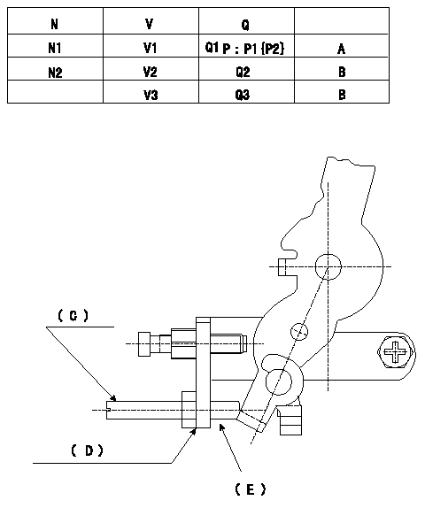
Adjusting method [applied voltage Vi, dummy bolt (C)]
1. Hold the dummy bolt (C) against the control lever at position N = N1, Q = Q1.
Fix using the lock nut.
2. When adjusting the potentiometer, position the control lever against the dummy bolt (C) and adjust the potentiometer so that the output voltage is V1 (V).
3. Remove the dummy bolt (C) after the completion of adjustment.
Confirm that the potentiometer output voltage is within the above mentioned standards between the control lever's adjusting point and the idling position.
N:Pump speed
V:Output voltage
Q:Injection quantity
P:Boost pressure
A:Adjusting point
B:Checking point
Q2:Idle
Q3:Full speed
(C): Dummy bolt
(D): Bracket for mounting the dummy bolt
(E): Part numbers of the dummy bolt and the nut
146526-3300 (bolt) 42L
013020-6040 (nut)
----------
N1=750r/min V1=2.80+-0.03V Q1=16.0+-1cm3/1,000st Vi=10V
----------
N1=750r/min N2=360r/min V1=2.80+-0.03V V2=0.62+-0.45V V3=-V Q1=16.0+-1.0cm3/1,000st Q2=15.8+-2.0(Idle)cm3/1,000st Q3=-cm3/1,000st Vi=-V P1=73.3kPa P2=550mmHg
----------
N1=750r/min V1=2.80+-0.03V Q1=16.0+-1cm3/1,000st Vi=10V
----------
N1=750r/min N2=360r/min V1=2.80+-0.03V V2=0.62+-0.45V V3=-V Q1=16.0+-1.0cm3/1,000st Q2=15.8+-2.0(Idle)cm3/1,000st Q3=-cm3/1,000st Vi=-V P1=73.3kPa P2=550mmHg
0000001901 W-CSD ADJUSTMENT
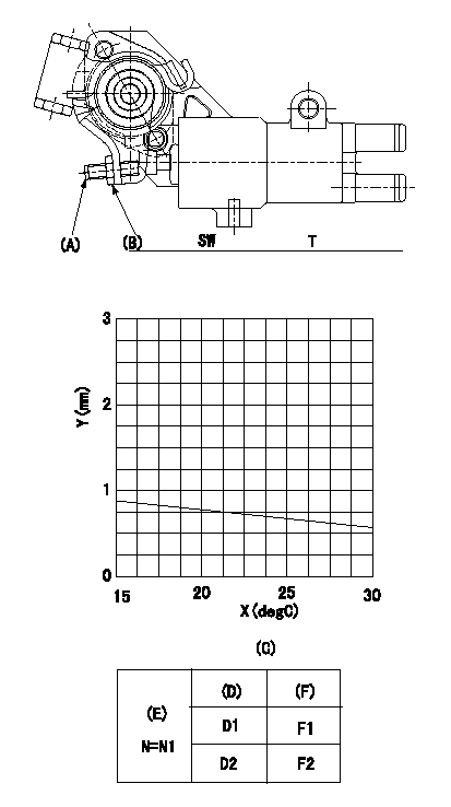
Adjustment of the W-CSD
Adjust the timer stroke
Adjust using the screw (A) so that the timer stroke is the same as the value determined from the graph function (C).
Fix using nut (B).
(C): Timer stroke: TA=-0.0175t + 1.15(-20 deg C <= t <= 20deg) (mm)
TA = -0.0225t + 1.25 ( 20 deg C <= t <= 60 deg C)
X:Temperature t (deg C)
Y:Timer stroke TA (mm)
(D): coolant temperature (deg C )
(E): coolant temperature: increase direction
N:Pump speed
(F): Timer piston stroke (mm)
----------
----------
SW=SW8 T=3.4~4.9N{0.35~0.5} N1=500r/min D1=20degC D2=-20degC F1=0.8+-0.4mm F2=1.6+-0.6mm
----------
----------
SW=SW8 T=3.4~4.9N{0.35~0.5} N1=500r/min D1=20degC D2=-20degC F1=0.8+-0.4mm F2=1.6+-0.6mm
Information:
T-T-T Procedure
A torque-turn-tighten (T-T-T) procedure is used in many specifications and instructions.1. Clean the bolt and nut threads.2. Put lubrication of the threads and the seat face of the bolt and nut.3. Turn the bolt or the nut tight according to the torque specification.4. Put a location mark on the part and on the bolt head or nut.5. Turn the bolt or the nut tighter the amount of degrees according to the specifications The side of a nut or bolt head can be used for reference if a mark can not be put on. Torque Wrench Extension
When a torque wrench extension is used with a torque wrench, the torque indication on the torque wrench will be less than the real torque.
(E) Torque wrench drive axis-to-torque wrench extension drive axis. (W) Mark on handle-to-torque wrench drive axis.1. Put a mark on the handle. Measure the handle from the mark to the axis of the torque wrench drive (W).2. Measure the torque wrench extension from the torque wrench drive to the axis of the torque wrench extension drive (E).3. To get correct torque indication (TI) when the real torque (RT) is known: Example: W = 304.8 mm (12 in); E = 65.0 mm (2.56 in); RT (from specifications) = 17 N m (125 lb ft). 4. Hold the torque wrench handle with the longest finger of the hand over the mark on the handle to get the real torque (RT) with low torque indication (TI) on the torque wrench.Locks
Flat metal locks must be installed properly to be effective. Bend one end of the lock around the edge of the part. Bend the other end against one flat surface of the nut of bolt head.Always install new locks in components which house moving parts.If lockwashers are installed on housings made of aluminum, use a flat washer between the lockwasher and the housing. Lines And Wires
When removing or disconnecting a group of lines or wires, tag each one to assure proper assembly.Lubrication
Where applicable, fill the compartments of the components serviced with the amount, type and grade of lubricant recommended in the Operation Maintenance Manual.Rust Preventive Compound
Clean the rust preventive compound from all machined surfaces of new parts before installing the part.Shims
When shims are removed, tie them together and identify them as to location. Keep shims clean and flat until they are reinstalled.Bearings
Anti-Friction Bearings
When an anti-friction bearing is removed, cover it to keep out dirt and abrasives. Wash the bearings in nonflammable cleaning solution and allow them to drain dry. The bearings may be dried with compressed air, but DO NOT SPIN THE BEARING. Discard the bearings if the races and balls or rollers are pitted, scored or burned. If the bearing is serviceable, coat it with oil and wrap it in clean paper. DO NOT unwrap new bearings until time of installation.The life of an anti-friction bearing will be shortened if not properly lubricated.Double Row, Tapered Roller
Double row, tapered roller bearings are precision fit during manufacture and the components are not interchangeable.
Have questions with 104746-1801?
Group cross 104746-1801 ZEXEL
Isuzu
104746-1801
9 460 611 709
8971338471
INJECTION-PUMP ASSEMBLY
4JG2-TC
4JG2-TC