Information injection-pump assembly
ZEXEL
104746-1341
1047461341
ISUZU
8971078650
8971078650
Rating:
Cross reference number
ZEXEL
104746-1341
1047461341
ISUZU
8971078650
8971078650
Zexel num
Bosch num
Firm num
Name
Calibration Data:
Adjustment conditions
Test oil
1404 Test oil ISO4113orSAEJ967d
1404 Test oil ISO4113orSAEJ967d
Test oil temperature
degC
45
45
50
Nozzle
105780-0060
Bosch type code
NP-DN0SD1510
Nozzle holder
105780-2150
Opening pressure
MPa
13
13
13.3
Opening pressure
kgf/cm2
133
133
136
Injection pipe
154805-7320
Injection pipe
Inside diameter - outside diameter - length (mm) mm 2-6-450
Inside diameter - outside diameter - length (mm) mm 2-6-450
Joint assembly
157641-4720
Tube assembly
157641-4020
Transfer pump pressure
kPa
20
20
20
Transfer pump pressure
kgf/cm2
0.2
0.2
0.2
Direction of rotation (viewed from drive side)
Right R
Right R
Injection timing adjustment
Pump speed
r/min
1000
1000
1000
Average injection quantity
mm3/st.
60.9
60.4
61.4
Difference in delivery
mm3/st.
3.5
Basic
*
Oil temperature
degC
50
48
52
Injection timing adjustment_02
Pump speed
r/min
500
500
500
Average injection quantity
mm3/st.
60
60
60
Oil temperature
degC
48
46
50
Injection timing adjustment_03
Pump speed
r/min
1000
1000
1000
Average injection quantity
mm3/st.
60.9
59.9
61.9
Difference in delivery
mm3/st.
3.5
Basic
*
Oil temperature
degC
50
48
52
Injection timing adjustment_04
Pump speed
r/min
1440
1440
1440
Average injection quantity
mm3/st.
58.9
58.9
58.9
Oil temperature
degC
50
48
52
Injection timing adjustment_05
Pump speed
r/min
1800
1800
1800
Average injection quantity
mm3/st.
59.2
59.2
59.2
Oil temperature
degC
50
48
52
Injection quantity adjustment
Pump speed
r/min
2100
2100
2100
Average injection quantity
mm3/st.
19.6
16.6
22.6
Difference in delivery
mm3/st.
5.5
Basic
*
Oil temperature
degC
52
50
54
Injection quantity adjustment_02
Pump speed
r/min
2300
2300
2300
Average injection quantity
mm3/st.
5
Oil temperature
degC
52
50
54
Injection quantity adjustment_03
Pump speed
r/min
2100
2100
2100
Average injection quantity
mm3/st.
19.6
16.6
22.6
Difference in delivery
mm3/st.
5.5
Oil temperature
degC
52
50
54
Governor adjustment
Pump speed
r/min
400
400
400
Average injection quantity
mm3/st.
13.2
11.2
15.2
Difference in delivery
mm3/st.
2
Basic
*
Oil temperature
degC
48
46
50
Governor adjustment_02
Pump speed
r/min
400
400
400
Average injection quantity
mm3/st.
13.2
11.2
15.2
Difference in delivery
mm3/st.
2
Oil temperature
degC
48
46
50
Timer adjustment
Pump speed
r/min
100
100
100
Average injection quantity
mm3/st.
74
69
79
Basic
*
Oil temperature
degC
48
46
50
Remarks
Full
Full
Timer adjustment_02
Pump speed
r/min
100
100
100
Average injection quantity
mm3/st.
74
69
79
Oil temperature
degC
48
46
50
Speed control lever angle
Pump speed
r/min
400
400
400
Average injection quantity
mm3/st.
0
0
0
Oil temperature
degC
48
46
50
Remarks
Magnet OFF at idling position
Magnet OFF at idling position
0000000901
Pump speed
r/min
1000
1000
1000
Overflow quantity
cm3/min
680
550
810
Oil temperature
degC
50
48
52
Stop lever angle
Pump speed
r/min
1000
1000
1000
Pressure
kPa
422
393
451
Pressure
kgf/cm2
4.3
4
4.6
Basic
*
Oil temperature
degC
50
48
52
Stop lever angle_02
Pump speed
r/min
1000
1000
1000
Pressure
kPa
422
393
451
Pressure
kgf/cm2
4.3
4
4.6
Basic
*
Oil temperature
degC
50
48
52
Stop lever angle_03
Pump speed
r/min
520
520
520
Pressure
kPa
255
206
304
Pressure
kgf/cm2
2.6
2.1
3.1
Oil temperature
degC
50
48
52
Stop lever angle_04
Pump speed
r/min
1700
1700
1700
Pressure
kPa
657
608
706
Pressure
kgf/cm2
6.7
6.2
7.2
Oil temperature
degC
50
48
52
0000001101
Pump speed
r/min
1000
1000
1000
Timer stroke
mm
2.5
2.3
2.7
Basic
*
Oil temperature
degC
50
48
52
_02
Pump speed
r/min
1700
1700
1700
Timer stroke
mm
5.8
5.5
6.1
Basic
*
Oil temperature
degC
50
48
52
_03
Pump speed
r/min
520
520
520
Timer stroke
mm
0.5
0.1
1.3
Oil temperature
degC
50
48
52
_04
Pump speed
r/min
1000
1000
1000
Timer stroke
mm
2.5
2.3
2.7
Basic
*
Oil temperature
degC
50
48
52
_05
Pump speed
r/min
1440
1440
1440
Timer stroke
mm
3.9
3.6
4.2
Oil temperature
degC
50
48
52
_06
Pump speed
r/min
1700
1700
1700
Timer stroke
mm
5.8
5.4
6.2
Basic
*
Oil temperature
degC
50
48
52
_07
Pump speed
r/min
1950
1950
1950
Timer stroke
mm
7.8
7.5
8.2
Oil temperature
degC
50
48
52
0000001201
Max. applied voltage
V
8
8
8
Test voltage
V
13
12
14
0000001401
Pump speed
r/min
1000
1000
1000
Average injection quantity
mm3/st.
31.8
31.3
32.3
Timer stroke TA
mm
2.2
2.2
2.2
Timer stroke variation dT
mm
0.3
0.1
0.5
Basic
*
Oil temperature
degC
50
48
52
_02
Pump speed
r/min
1000
1000
1000
Average injection quantity
mm3/st.
31.8
30.8
32.8
Timer stroke variation dT
mm
0.3
-0.1
0.7
Basic
*
Oil temperature
degC
50
48
52
_03
Pump speed
r/min
1000
1000
1000
Average injection quantity
mm3/st.
16.7
15.7
17.7
Timer stroke variation dT
mm
1
0.4
1.6
Oil temperature
degC
50
48
52
Timing setting
K dimension
mm
3.3
3.2
3.4
KF dimension
mm
5.8
5.7
5.9
MS dimension
mm
0.7
0.6
0.8
Pre-stroke
mm
0.1
0.08
0.12
Control lever angle alpha
deg.
18
14
22
Control lever angle beta
deg.
31
26
36
Test data Ex:
0000001801 W-CSD ADJUSTMENT
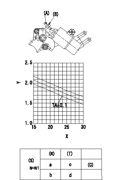
Adjustment of the W-CSD
Adjustment of the timer advance angle
1. Determine the timer advance angle using the graph (graph TA).
2. Adjust using screw so that the timer advance angle determined in item (1) is obtained. Then fix using nut (B).
X:Temperature t (deg C)
Y:Timer stroke TA (mm)
(S) Cooling water temperature: increase direction
(R) Cooling water temperature (deg C)
(T) Timer piston stroke (mm)
(C) Standard point
N:Pump speed
----------
TA=-0.0345t+2.59
----------
N1=500r/min a=20degC b=-20degC c=1.9+-0.4mm d=3.3+-0.6mm
----------
TA=-0.0345t+2.59
----------
N1=500r/min a=20degC b=-20degC c=1.9+-0.4mm d=3.3+-0.6mm
0000001901 V-FICD ADJUSTMENT
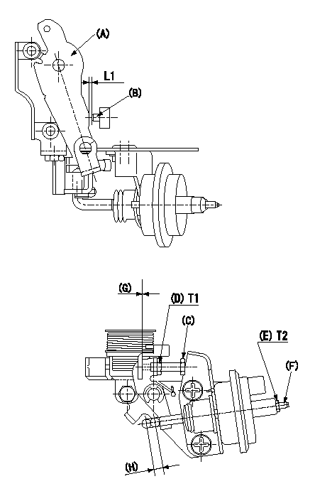
Adjustment of the V-FICD
1. Insert a shim L1 between the control lever (A) and the idle adjusting screw (B) and adjust using the FICD adjusting screw (C) so that the actuator moves through its full stroke. Then, fix using nut (D).
If adjustment with the FICD adjusting screw (C) is not possible, adjust by moving the actuator stroke with (E) and (F).
2. Apply P1 to the actuator and confirm the full stroke. After release, confirm that the gap between the control lever (A) and the FICD adjusting screw (C) is at least L2.
(G) L2 or above at actuator release
(H) Actuator stroke L3
----------
L1=0.90+-0.1mm L2=0.5mm L3=5mm P1=-53.3kPa(-400mmHg)
----------
L1=0.9+-0.1mm T1=1.2~1.5N-m(0.12~0.15kgf-m) T2=3.4~4.9N-m(0.35~0.50kgf-m)
----------
L1=0.90+-0.1mm L2=0.5mm L3=5mm P1=-53.3kPa(-400mmHg)
----------
L1=0.9+-0.1mm T1=1.2~1.5N-m(0.12~0.15kgf-m) T2=3.4~4.9N-m(0.35~0.50kgf-m)
0000002001 A/T PLATE ADJUSTMENT
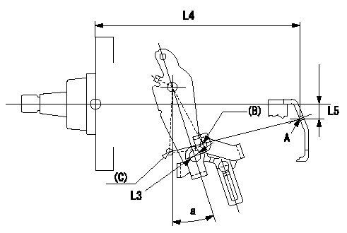
A/T plate adjustment
Rotate the control lever from the idle position (B) to the full-speed position (C).
Adjust the A/T plate (A) so that (A) (C) - (A) (B) = L1, and fix.
When fixing, fix the A/T plate within the range L3 from the center of the control lever's wire hole (hole L2).
(B) Idle position
(C) Full position
----------
L1=32.9+-1mm L2=Dia.8.5mm L3=Dia.9.2mm
----------
L3=Dia.9.2mm L4=169.8mm L5=12.4mm a=18+-4deg
----------
L1=32.9+-1mm L2=Dia.8.5mm L3=Dia.9.2mm
----------
L3=Dia.9.2mm L4=169.8mm L5=12.4mm a=18+-4deg
0000002101 POTENTIOMETER ADJUSTMENT

A:Lever position
V:Output voltage
C:Lever angle
Vi:Applied voltage
D:Full speed
E:Idle
----------
----------
V1=8.2+-0.03V V2=3.94--V V3=10V V4=10V C1=31+-5deg C2=0deg
----------
----------
V1=8.2+-0.03V V2=3.94--V V3=10V V4=10V C1=31+-5deg C2=0deg
0000002201 STARTING I/Q ADJUSTMENT
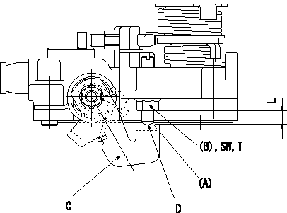
Starting injection quantity adjustment
Adjust the adjusting bolt A so that the starting injection quantity adjustment is within the standards.
Fix using nut (B).
Screw (A) protrusion: L
C = stop lever
D = no clearance
----------
L=2~7mm
----------
L=2~7mm T=6~9Nm(0.6~0.9kgfm) SW=SW10
----------
L=2~7mm
----------
L=2~7mm T=6~9Nm(0.6~0.9kgfm) SW=SW10
Information:
(1) Thickness of spacer plate ... 9.970 0.025 mm (.3925 .0010 in) Thickness of spacer plate gasket ... 0.208 0.025 mm (.0082 .0010 in) For height of liner over top of spacer plate make reference to Cylinder Liner Projection.(2) Camshaft bearing bore (installed) ... 58.80 0.06 mm (2.315 .002 in) Bore in block for camshaft bearings ... 65.100 0.025 mm (2.5630 .0010 in)(3) Bore in block for main bearings (standard size) ... 96.926 0.013 mm (3.8160 .0005 in) Bore in block for main bearings 0.51 mm (.020 in) oversize ... 97.436 0.013 mm (3.8361 .0005 in)(4) Dimension from center of main bearing bore to top of cylinder block (new) ... 383.515 0.165 mm (15.0990 .0064 in)(5) Dimension from center of main bearing bore to bottom of cylinder block (new) ... 153.99 0.10 mm (6.063 .004 in)(6) Torque for bolts holding bearing caps for main bearings: a. Put 2P2506 Thread Lubricant on threads and washer face.b. Tighten all bolts to ... 41 4 N m (30 3 lb ft)c. Put a mark on each bolt and cap.d. Tighten all bolts from mark ... 90 5° Install bearing caps with the part number toward the front of the engine. Be sure that the mark (number) on the bearing cap next to the bolt hole is in agreement with the mark in the cylinder block.(7) Clearance between main bearing cap and cylinder block ... 0.033 mm (.0013 in) tight to 0.043 mm (.0017 in) loose Main bearing cap width ... 165.095 0.020 mm (6.4998 .0008 in)Width of cylinder block for main bearing cap ... 165.100 0.018 mm (6.5000 .0007 in) (8) Piston cooling orifice.
There are holes in the bores for the main bearings, between the cylinders for piston cooling orifices. These holes must have orifices (8) installed.
(9) Distance two dowels extend from the surface of the cylinder block ... 19.8 0.5 mm (.78 .02 in)(10) Distance hollow dowel extends from the surface of the cylinder block ... 16.0 0.5 mm (.63 .02 in)(11) Depth to install two dowels below the surface of the cylinder block (apply 7M7456 Bearing Mount) ... 1.0 0.5 mm (.04 .02 in)(12) Distance dowels extend from the front face of the cylinder block ... 22.4 0.5 mm (.88 .02 in)(13) Distance stud extends from the front face of the cylinder block ... 15.7 0.5 mm (.62 .02 in)(14) Distance two dowels extend from the rear face of the cylinder block ... 12.7 0.5 mm (.50 .02 in)